Magnetoelastic coupling induced magnetic anisotropy in Co2(Fe/Mn)Si thin films
Abstract
The influence of epitaxial strain on uniaxial magnetic anisotropy of Co2FeSi (CFS) and Co2MnSi (CMS) Heusler alloy thin films grown on (001) SrTiO3 (STO) and MgO is reported. The in-plane biaxial strain is susceptible to tune by varying the thickness of the films on STO, while on MgO the films show in-plane easy axis for magnetization () irrespective of their thickness. A variational analysis of magnetic free energy functional within the Stoner-Wohlfarth coherent rotation model with out-of-plane uniaxial anisotropy for the films on STO showed the presence of magnetoelastic anisotropy with magnetostriction constant (12.220.07)10-6 and (2.020.06)10-6, in addition to intrinsic magnetocrystalline anisotropy -1.72106 erg/cm3 and -3.94106 erg/cm3 for CFS and CMS, respectively. The single-domain phase diagram reveals a gradual transition from in-plane to out-of-plane orientation of magnetization with the decreasing film thickness. A maximum canting angle of 41.5∘ with respect to film plane is predicted for the magnetization of the thinnest (12 nm) CFS film on STO. The distinct behaviour of in the films with lower thickness on STO is attributed to strain-induced tetragonal distortion.
I Introduction
The Heusler alloys have taken the center stage as spintronics
materials due to their high degree of spin polarization, high
Curie temperature, and low magnetic damping.Katsnelson ; Graf
By tuning the magnetic parameters such as coercivity, anisotropy,
exchange interactions and damping processes, one can suitably
tailor these materials for magnetic random access memory, magnetic
logics, spin-transistors, and related potential applications.
However, in most of such applications the magnetic alloy has to be
in a thin film form in which its magnetic characteristics can be
significantly different due to film thickness, crystallographic
orientation, growth related strains and interfacial reactions. One
such characteristics is magnetic anisotropy, which should be large
for magnetic storage applications, and which also determines the
magnetization reversal processes in magnetic switching devices.
Till now, a large number of full-Heusler alloy thin films have
been grown on various substrates. Some examples of this are
Co2MnGe on GaAsYang and Al2O3,Belmeguenai
Co2MnSi on GaAs,Wang MgO,Him ; Him1 ; Bosu and
Al2O3,LJSingh Co2FeAl0.5Si0.5 on
MgO,Trudel Co2FeSi on GaAs,Hashimoto ; Jenichen
Al2O3,Schneider and MgOSchneider as well as on
SrTiO3 (STO).Anupam ; Prasanna ; Him2 While the substrate
lattice parameter, growth, thermal annealing condition and film
thickness in these cases vary significantly, the effect of such
condition on magnetic anisotropy of the films is seldom addressed.
In Heusler alloys films, one expects a four-fold anisotropy due to
the cubic symmetry of the unit cell, while in-plane uniaxial
anisotropy has also been observed for the case of Co2FeSi grown
on GaAs.Hashimoto The presence of additional uniaxial
anisotropy has resulted in multistep magnetization switching in
some Heusler alloy films.Yang ; Wang Moreover, Gabor
et al. have shown that Co2FeAl films can have three
types of in-plane anisotropies, namely biaxial (fourfold cubic
anisotropy) and two uniaxial anisotropies parallel to the biaxial
easy and hard axes.Gabor In some cases, stripe domains have
also been seen due to magnetic frustration between two
energetically equivalent easy axis.Liu The interface
between the film and substrate also affects the orientation of
magnetization significantly. For example, the out-of-plane
magnetic easy axis in Co2FeAl films on Cr-buffered MgO
substrate seemed to be induced by the interfacial anisotropy which
appears after annealing the films in the presence of magnetic
field applied along out-of-plane direction.Wen
The magnetic anisotropy in thin films originates from fundamental factors such as the spin-orbit interaction in the material which controls magnetocrystalline anisotropy and/or due to growth related strain. Any change in the lattice via strain will change the distances between the magnetic atoms and alter the interaction energy, which decides the magnetoelastic anisotropy. The strain therefore becomes a tuning parameter for magnetic anisotropy and can be varied by a choice of substrates of different lattice parameter or films of varied thickness. A consequence of the strain related anisotropy is the rotation of magnetic easy axes from in-plane to out-of-plane configuration or vice versa. While a strain dependence of in-plane anisotropy has been reported for Co2FeAl/MgO thin films,Gabor to the best of our knowledge, strain driven out-of-plane anisotropy has not been reported for Heusler alloy films. Here we report a detailed study of the magnetic anisotropy of Co2(Fe/Mn)Si [CF(M)S] films of various thickness deposited on (001) MgO and (001) STO crystals. The in-plane biaxial strain was gradually varied from compressive (for the films on STO) to tensile (for the films on MgO) by depositing the films of different thickness. We have specifically focussed on the strain dependence of out-of-plane uniaxial magnetic anisotropy in CF(M)S/STO films and established how the strain induced magnetic anisotropy affects the direction of magnetization (). It is seen that the tuning of magnetoelastic coupling by varying the film thickness results in the rotation of the magnetization vector towards out-of-plane direction as the film thickness is lowered.
II Experimental details
We have previously demonstrated that the CF(M)S films on SrTiO3 and MgO processed at 600 have better crystalline quality as compared to those annealed at lower temperatures.Anupam ; Him ; Him1 Therefore, for studies of anisotropy reported here, we mainly concentrate on the films processed at 600. The cubic lattice parameter ( 0.5656 nm) of CF(M)S matches quite well with the face diagonal () of (001) STO and MgO. The lattice misfit [ = ] of CM(F)S with STO and MgO lies within 6. Taking advantage of close matching of the lattice parameters, we have prepared a series of CF(M)S thin films of various thickness (t = 5-100 nm) epitaxially on (001) STO and MgO using pulsed laser deposition technique. The details of thin film preparation are described in our earlier reports.Him ; Him1 ; Anupam ; Prasanna The structural characterization of the films has been done by X-ray diffraction (PANalytical X′Pert PRO X-ray diffractometer) in -2, , , and grazing incidence X-ray diffraction (GIXRD) modes. The magnetic measurements were performed in a vibrating sample magnetometer (EV7 VSM) at room temperature.
III Results and discussion
III.1 Structural characterization
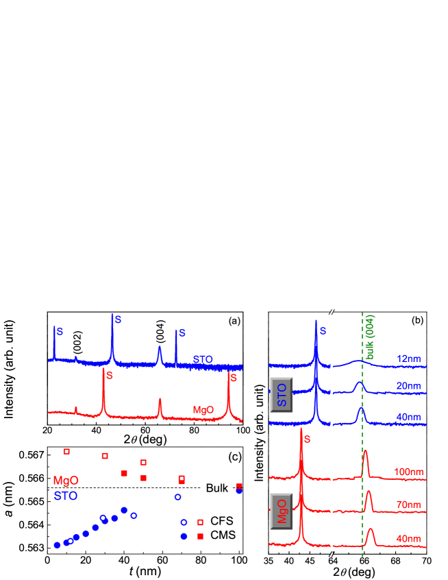
The X-ray diffraction reveals (00) oriented growth of CF(M)S films on STO and MgO [Fig. 1(a)]. Further evidence of (00) texturing is provided by the rocking curves about (004) reflection. The full width at half maximum of these films are less than 1.9∘, which corresponds to a crystallite size of 5 nm.Prasanna Moreover, the scans confirm the epitaxial growth of the films with the relation [100] CF(M)S [110] STO or MgO. The presence of (111) superlattice, which governs the ordering of the Mn(or Fe) and Si sublattices, and (022) fundamental diffraction line, which confirms the presence of ordering in the films, are two important indicators of the structural ordering in the films. From GIXRD measurements, we infer the degree of ordering in the films to be more than 85. Figure 1(b) shows the scan about (004) peak for films of various thickness on MgO and STO substrates. A clear shift of the Bragg reflections towards higher (lower) scattering angle () is seen for the films grown on MgO (STO) as the thickness is reduced. The out-of-plane lattice parameter () obtained from these scans decreases (increases) for the films grown on STO (MgO) with the increasing . This can be understood in terms of the strain induced in the films due to lattice misfit. The positive misfit value for STO ( = 2.4) results in in-plane compressive strains, which decreases the in-plane lattice parameter () as verified by off-axis scans about (022) peak. Assuming the volume () preserving distortion, we expect an increase in with decreasing for the films grown on STO. The films with lower thickness experience a relatively strong tetragonal distortion. As the film thickness increases, the distortion relax by formation of misfit dislocations. With increase in thickness, the in-plane strain [=()/] approaches zero as seen in Fig. 1(c). We observe that the thinnest film ( 5 nm) on STO is under highest biaxial compressive strain of = -0.44 % while the thicker films undergo partial strain relaxation with 100 nm film attaining bulk values. Similarly, the tensile strain in the Heusler alloy films on MgO disappears on increasing their thickness.

III.2 Magnetization
We first discuss the behavior of magnetic hysteresis loops
[] for in-plane (along [110]) and out-of-plane (along [001])
field configurations [See Fig. 2(a-c)]. The hysteresis loops of
the films on MgO clearly show an in-plane easy axis for
magnetization () as revealed by the squareness
of the loop in Fig. 2(a). This result is the same for thicker CFS
films on STO [Fig. 2(b)]. However, for our thinnest film on STO,
we observe a significantly higher out-of-plane magnetization,
which suggests the possibility of tilted with
respect to the film plane. Figure 2(d) shows the remanent
magnetization () at different angles () of the field
with respect to the film plane, which looks like a dumbbell with
two lobes almost separated from each other for CMS(40 nm)/STO
film. Clearly, the / is maximum for
and 180∘ (in-plane directions) while
it is almost zero at 90∘ and 270∘ (out-of-plane
directions). This observation confirms the presence of in-plane
easy axis for thicker films on STO. However, in the case of CMS(5
nm)/STO film, two lobes are joined and thus the is
substantially higher for 90∘ and
270∘. This suggests a canted easy axis instead of an
in-plane one as observed in thicker films. We believe that the
substrate-film interface plays an important role in tilting the
magnetization away from the film plane. The upper panel in Fig.
2(e) shows the thickness dependence of the squareness
() of magnetization extracted from in-plane M(H) loops.
In case of films on MgO, it remains almost constant whereas, for
the films on STO, we notice a gradual decline in / with
decreasing thickness, which indicates the deviation of easy axis
from the film plane. Although the lowest observed value (
0.2 for 5 nm film) does not point towards a distinct out-of-plane
easy axis, it certainly indicates some canting of
away from the film plane.
The coercivity of a material is the principal property related to the rate of change of magnetic relaxation between the remanent and demagnetized states. At absolute zero, it measures the barrier height that is required by magnetic moments to overcome the demagnetized state. The variation of the coercivity () of the films with thickness is plotted in the lower panel of Fig. 2(e). We observe that decreases gradually with increasing thickness in all cases. This may be attributed to a lowering of defect concentration due to enhancing crystalline quality or due to lowering of strain in thicker films. Moreover, the reduction of can also be due to the changes in the grain size and the surface roughness of the film with its thickness or related to the fact that the film thickness decreases to a point where the domain wall thickness becomes comparable to the film thickness. The follows a power law type dependence on of the form: t-n with and for CMS and CFS films on STO, respectively. The value of depends on the deposition conditions and the choice of ferromagnet, and can have values from -0.3 to -1.5.Neel ; Tolman ; Wolf
We have carried out an analysis of the hard axis magnetization loops in the framework of Stoner-Wohlfarth formalism.Stoner The total magnetic free energy () of the film in tetragonal symmetry can be expressed as:
| (1) |
where and are second and fourth order uniaxial anisotropy constants, respectively while is in-plane biaxial anisotropy constant. The are the direction cosines of the magnetization vector . The fourth term of Eq. (1) is the Zeeman energy and the last term represents the thin film demagnetization energy. For out-of-plane field hysteresis loop i.e. when is applied along [001], will rotate from the [110] (in-plane easy axis) to [001] direction and thus the term is always zero. The minimization of total magnetic free energy for an out-of-plane field yields the equilibrium magnetization in the field direction given by the relation:
| (2) |
The values of and can be obtained by fitting Eq. (2) to the hysteresis loops. The inset of Fig. 3(a) shows the plot of vs. for 68 nm thick CFS/STO film. The intercept and slope of the linear fit yield and , respectively. The deviation in upper part of the curve from the linearity occurs as approaches saturation, while the deviation at lower can be attributed to magnetic domain effects.Wang2 All the films on MgO show in-plane easy axis without any substantial change in () loops with thickness. So the determination of anisotropy coefficients for these films will not be reliable. While we observed clear change in () loops for the films on STO with varying thickness. Hence we will only focuss on the later films in order to gain further insight of the magnetic state.
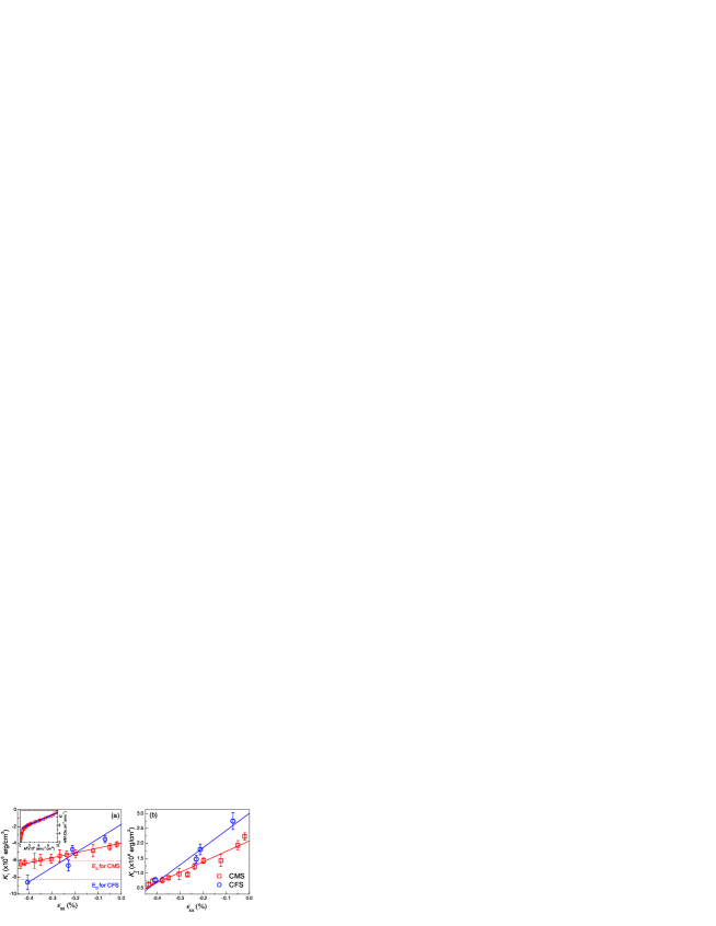
Figure 3 shows the values of and deduced from Eq. (2) for CF(M)S/STO films as a function of . We clearly observe a monotonic increase in anisotropies with the increasing strain. Moreover, the values of are quite similar to previously reported values.Him The is connected to through the magnetoelastic coupling parameters and can be expressed as = /2.Culity The first term represents the strain independent magnetic anisotropy, commonly known as ”magnetocrystalline anisotropy”, which originates from the inherent crystal structure of ferromagnet.Culity The linear fits to data yield -1.72106 erg/cm3 and -3.94106 erg/cm3 for CFS and CMS, respectively [See Fig. 3(a)]. The second term is purely related to the strain induced anisotropy, which depends linearly on stress and the magnetostriction constant . The stress can be represented as , where the Youngs modulus () can be expressed in terms of elastic stiffness constants ( and ) as follows: .Ledbetter Assuming theoretical values of ’s,Chen we find 93 GPa for CFS and 192 GPa for CMS. Using these values, the linear fits to data yield (12.220.07)10-6 and (2.020.06)10-6 for CFS and CMS, respectively. To the best of our knowledge, we are unaware of any values of and for these compounds reported in literature. The values of are comparable to the reported value of 1510-6 for another Heusler alloy Co2MnAlQiu while is of the order of 10-5 for half metallic manganites.Donnell ; Lofland
Our expression for in case of biaxial stress () is same as the expression for uniaxial stress (, ) induced anisotropy, i.e. . But these two cases are fundamentally different. In the former scenario, a uniaxial anisotropy is induced perpendicular to the plane (along -axis) while for latter case the uniaxial anisotropy is along the direction of applied stress (along -axis). The other anisotropy constant also shows a linear dependence with as shown in Fig. 3(b). Such linear relation has been predicted for a cubic system under biaxial strain and experimentally verified for Cu-Ni systems.Handley Similar to the case for , we observe a substantial contribution to coming from magnetocrystalline origin in addition to the magnetoelastic couplings.
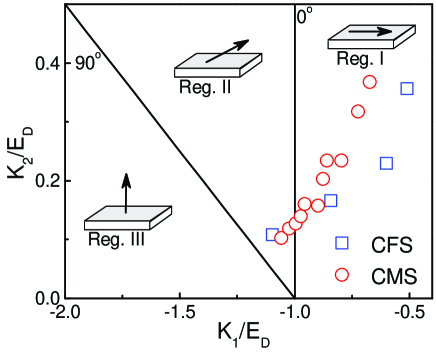
The direction of magnetic easy axis depends sensitively on anisotropy energy dependent on and and the demagnetization energy (=2). Only consideration of second-order angular term gives an out-of-plane magnetization state for / -1 while becomes in-plane for -1 /. However, the fourth order anisotropy term introduces the canting states of allowing a gradual transition between the in-plane and out-of-plane states.Handley ; Gyanendra Figure 4 shows the general single-domain magnetic phase diagram for a system with free energy given by Eq. (1) in zero magnetic field assuming a coherent rotation of magnetization. The films whose anisotropy data lie in Region II have canted magnetization states, where the canting angle (the angle between and film plane) can be obtained from the relation:Handley . The CFS (12 nm)/STO film has = 41.5∘ while the angles for 5 nm and 10 nm thick CMS/STO films are 31.8∘ and 17.9∘, respectively. The data for thicker films fall into Region I, which suggests that easy axis of magnetization is in-plane. Clearly, it can be inferred that easy axis changes from in-plane to canted orientation with increasing compressive strain. Hence, there is a possibility to get the perpendicular magnetic anisotropy in case of films with higher strain. This can be achieved either by lowering the film thickness or choosing a substrate with a larger positive misfit.
IV Summary
We have presented a study to correlate the crystallographic structure and the magnetic state of Co2FeSi and Co2MnSi films on (001) STO and MgO substrates. The films on STO are under in-plane biaxial compressive strain while a tensile strain is observed in the films on MgO. The strain gradually relaxes with increasing film thickness. The hysteresis loops clearly show an in-plane easy axis for all the films on MgO, however, for the films on STO, the out-of-plane component of magnetization increases with decreasing thickness. The analysis of magnetic free energy functional within the Stoner-Wohlfarth coherent rotation model with out-of-plane uniaxial anisotropy predicts a canted magnetization state for the films on STO, which gradually moves towards in-plane state with increasing thickness in a single-domain magnetic phase space. The uniaxial anisotropy terms have two distinct contributions; first one is intrinsic magnetocrystalline anisotropy, which is strain independent and the other one is magnetoelastic anisotropy. We have extracted various anisotropy terms ( 106 erg/cm3) and magnetostriction constants 10-6 of Co2FeSi and Co2MnSi for the first time. We also predict maximum canting angles of 41.5∘ and 31.8∘ for Co2FeSi (12 nm) and Co2MnSi (5 nm) on STO, respectively. These results prove that the epitaxial strain is a useful parameter to tailor the magnetic anisotropy in thin film of Heusler alloys, which could lead to the realization of out-of-plane magnetic anisotropy on oxide substrates for fabrication of memory devices.
V Acknowledgements
The authors thank M. Shivakumar for his help in magnetization measurements. H.P. and P.K.R. acknowledge financial support from Indian Institute of Technology Kanpur and Council for Scientific and Industrial Research (CSIR), Government of India. This work is partly supported by CSIR, New Delhi [Grant No. 80(0080)/12/EMR-II]. R.C.B. acknowledges J. C. Bose Fellowship of the Department of Science and Technology, Government of India.
References
- (1) M. I. Katsnelson, V. Yu. Irkhin, L. Chioncel, A. I. Lichtenstein, and R. A. de Groot, Rev. Mod. Phys. 80, 315 (2008).
- (2) T. Graf, C. Felser, and S. S. P. Parkin, Prog. Solid State Chem. 39, 1 (2011).
- (3) F. Y. Yang, C. H. Shang, C. L. Chien, T. Ambrose, J. J. Krebs, G. A. Prinz, V. I. Nikitenko, V. S. Gornakov, A. J. Shapiro, and R. D. Shull, Phys. Rev. B 65, 174410 (2002).
- (4) M. Belmeguenai, F. Zighem, Y. Roussigné, S-M. Chérif, P. Moch, K. Westerholt, G. Woltersdorf, and G. Bayreuther, Phys. Rev. B 79, 024419 (2009).
- (5) W. H. Wang, M. Przybylski, W. Kuch, L. I. Chelaru, J. Wang, Y. F. Lu, J. Barthel, H. L. Meyerheim, and J. Kirschner, Phys. Rev. B 71, 144416 (2005).
- (6) H. Pandey, P. C. Joshi, R. P. Pant, R. Prasad, S. Auluck, and R. C. Budhani, J. Appl. Phys. 111, 023912 (2012).
- (7) H. Pandey and R. C. Budhani, J. Appl. Phys. 113, 203918 (2013).
- (8) S. Bosu, Y. Sakuraba, K. Uchida, K. Saito, T. Ota, E. Saitoh, and K. Takanashi, Phys. Rev. B 83, 224401 (2011).
- (9) L. J. Singh, Z. H. Barber, Y. Miyoshi, Y. Bugoslavsky, W. R. Branford, and L. F. Cohen, Appl. Phys. Lett. 84, 2367 (2004).
- (10) S. Trudel, G. Wolf, J. Hamrle, B. Hillebrands, P. Klaer, M. Kallmayer, H-J. Elmers, H. Sukegawa, W. Wang, and K. Inomata, Phys. Rev. B 83, 104412 (2011).
- (11) M. Hashimoto, J. Herfort, H.-P. Scöhnherr, and K. H. Ploog, Appl. Phys. Lett. 87, 102506 (2005).
- (12) B. Jenichen, J. Herfort, T. Hentschel, A. Nikulin, X. Kong, A. Trampert, and I. Žižak, Phys. Rev. B 86, 075319 (2012).
- (13) H. Schneider, G. Jakob, M. Kallmayer, H. J. Elmers, M. Cinchetti, B. Balke, S. Wurmehl, C. Felser, M. Aeschlimann, and H. Adrian, Phys. Rev. B 74, 174426 (2006).
- (14) Anupam, P. C. Joshi, P. K. Rout, Z. Hossain, and R. C. Budhani, J. Phys. D: Appl. Phys. 43, 255002 (2010).
- (15) P. K. Rout, H. Pandey, L. Wu, Anupam, P. C. Joshi, Z. Hossain, Y. Zhu, and R. C. Budhani (Manuscript submitted).
- (16) V. Toutam, H. Pandey, S. Singh, and R. C. Budhani, AIP ADVANCES 3, 022124 (2013).
- (17) M. S. Gabor, T. Petrisor Jr., C. Tiusan, M. Hehn, and T. Petrisor, Phys. Rev. B 84, 134413 (2011).
- (18) Y. Liu, L. R. Shelford, V. V. Kruglyak, R. J. Hicken, Y. Sakuraba, M. Oogane, Y. Ando, and T. Miyazaki, J. Appl. Phys. 101, 09C106 (2007).
- (19) Z. Wen, H. Sukegawa, S. Mitani, and K. Inomata, Appl. Phys. Lett. 98, 242507 (2011).
- (20) I. Galanakis, P. H. Dederichs, and N. Papanikolaou, Phys. Rev. B 66, 174429 (2002).
- (21) L. Néel, J. Phys. Radium 17, 250 (1956).
- (22) C. H. Tolman, J. Appl. Phys. 38, 4538 (1967).
- (23) I. W. Wolf, J. Appl. Phys. 33, 1152 (1962).
- (24) E. C. Stoner and E. P. Wohlfarth, Philos. Trans. R. Soc. London A 240, 599 (1948).
- (25) Z.-H. Wang, H. Kronmüller, O. I. Lebedev, G. M. Gross, F. S. Razavi, H.-U. Habermeier, and B. G. Shen, Phys. Rev. B 65, 054411 (2002).
- (26) B. D. Cullity, Introduction to Magnetic Materials (Addison-Wesley, Reading, MA, 1972).
- (27) H. M. Ledbetter and R. P. Reed, J. Phys. Chem. Ref. Data 2, 531 (1973).
- (28) X.-Q. Chen, R. Podloucky, and P. Rogl, J. Appl. Phys. 100, 113901 (2006).
- (29) J. J. Qiu, G. C. Han, W. K. Yeo, P. Luo, Z. B. Guo, and T. Osipowicz, J. Appl. Phys. 103, 07A903 (2008).
- (30) J. O′Donnell, M. S. Rzchowski, J. N. Eckstein, and I. Bozovic, Appl. Phys. Lett. 72, 1775 (1998).
- (31) S. E. Lofland, S. M. Bhagat, H. L. Ju, G. C. Xiong, T. Venkatesan, R. L. Greene, and S. Tyagi, J. Appl. Phys. 79, 5166 (1996).
- (32) K. Ha and R. C. O′Handley, J. Appl. Phys. 87, 5944 (2000).
- (33) G. Singh, P. K. Rout, R. Porwal, and R. C. Budhani, Appl. Phys. Lett. 101, 022411 (2012).