Generation of microwave radiation by nonlinear interaction of a high-power, high-repetition rate, 1064-nm laser in KTP crystals
Abstract
We report measurements of microwave (RF) generation in the centimeter band accomplished by irradiating a nonlinear KTiOPO4 (KTP) crystal with a home-made, infrared laser at nm as a result of optical rectification (OR). The laser delivers pulse trains of duration up to s. Each train consists of several high-intensity pulses at an adjustable repetition rate of approximately GHz. The duration of the generated RF pulses is determined by that of the pulse trains. We have investigated both microwave- and second harmonic (SHG) generation as a function of the laser intensity and of the orientation of the laser polarization with respect to the crystallographic axes of KTP.
pacs:
(350.4010) Microwaves, (160.4330) Nonlinear optical materials, (160.2100) Electro-optical materials, (140.4050) Mode-locked lasersOptical heterodyning is at the basis of several techniques to produce microwave signals Bridges and Strnad (1972); Yao (2009); Khan2010 . Two adjacent laser lines are brought to beat in a nonlinear crystal to generate signals at the difference frequency, which lies in the microwave domain. Authors have demonstrated generation of beat notes at frequencies from a few GHz up to the THz band Niebuhr (1963); Lengfellner (1987).
Optoelectronic oscillators have also been developed that generate spectrally pure microwave signals by modulating continuous laser light in interferometric devices leader2002 , whose performance is limited by the bandwidth of the state-of-the-art photodetectors Neyer and Voges (1982); Yao and Maleki (1996).
In this paper we report about a novel technique of microwave and mm-wave signal photonic generation. The method is demonstrated at GHz but can be extended up to a few hundreds GHz keller2002 ; Keller (2003). It is based on the fast response of a second order nonlinear crystal to a pulse train delivered by a high-intensity, mode-locked laser system, whose repetition rate is in the RF domain. The irradiation of such a crystal with a train of short laser pulses produces a time-dependent polarization in the crystal as a consequence of optical rectification (OR) bass1962 . This process gives origin to the emission of microwave radiation that can be transferred to any receivers, either a cavity or a waveguide, without the bandwidth limitation of photodetection.
OR has also been used to produce subpicoseconds THz pulses by using ultrashort laser pulses in a number of nonlinear crystals zhang1992 ; graf2000 .
We used a KTiOPO4 (KTP) crystal because its non centrosymmetric, orthorombic crystal structure belonging to the point symmetry group Yariv and Yeh (2007) endows it with a strong second order nonlinearity. Its electro-optic coefficients are well known Bierlein and Arweiler (1986); boulanger1994 ; pack2004 and it is, thus, very well suited to characterize our technique to produce RF radiation.
In Fig. (1) a scheme of the experimental setup is shown. The KTP crystal used (EKSMA Optics) is a parallelepiped mm3 in size whose long axis is aligned in the direction of the laser propagation. The crystal is cut in a way that its optical axis forms an angle with necessary for phase matching purposes in a previous experiment. It is mounted in the center of a rectangular RF cavity (C) designed so as to sustain a TE111 mode. Its resonance frequency can be tuned to the laser pulses repetition rate that can be varied in the range GHz to GHz.
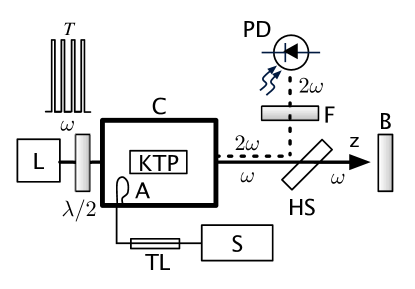
The crystal can be rotated about the axis to maximize the coupling of the RF emission with the cavity mode. The quality factor of the loaded cavity is A critically coupled antenna (A) is used to pick up the RF signal that is directly fed to the input of the oscilloscope (S).
The infrared (nm) laser (L), described elsewhere braggio2011 , is set to deliver one ns or more-long pulse train every second. The pulse width is ps and each train contains of them, the pulse repetition rate being set at GHz. In this way, a restricted-band frequency comb Cundiff and Ye (2003) is generated with mode frequencies where rad/s is the laser frequency. Because of the gaussian shape and duration of the individual pulses, the highest overtone of nonnegligible amplitude has index so that and all the frequencies in the laser spectrum are in the optical region boyd1971 .
The maximum laser intensity value is limited to MW/cm2 in order to keep well below the damage threshold (MW/cm2 for ns long pulses). can be reduced by inserting calibrated neutral density filters in the laser path. We note that the lower limit to the laser intensity is set by the requirement that it forces the nonlinear response of the crystal. We experimentally observed microwave generation by KTP with as low as
The laser polarization can be rotated relative to the crystal axes by means of a wave plate mounted on a rotating goniometer. The laser beam has an ellissoidal gaussian profile with semiaxes mm and mm, respectively, and is fully projected onto the antireflection coated, entrance face of the crystal. The light exiting the crystal output face contains the contribution due to SHG and to the pump laser. The SH is picked out by a combination of a harmonics separator (HS) and a bandpass filter (F) and is measured by a photodiode (PD) whose output voltage is proportional to its intensity. A bolometer (B) is used to monitor the laser stability.
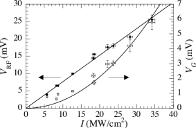
In Fig. (2) we show the amplitude of the microwave signal and the SH intensity as a function of the laser intensity for a fixed position of the plate. In our experiment, the efficiency of SHG is of a few %. The presence of SH is a clear sign of a quadratic nonlinear effect. Actually, the proportionality constant depending on the second-order susceptibility tensor for the mixing of two identical frequencies
By contrast, the antenna signal is proportional to the time derivative of the microwave polarization field that depends on the quasi static polarization induced by OR. Thus, the amplitude of the RF signal is directly proportional to the laser intensity, the proportionality constant depending on The experimental data confirm these expectations.
To further verify that the microwave radiation is produced by OR, we measured the dependence of on the angle by which the direction of the laser polarization is rotated by the plate. The results are displayed in Fig. (3). shows a marked 4-fold periodicity and can be accurately fitted to the following form

| (1) |
with mV, mV. has no physical relevance.
As the antenna signal is proportional to the first time derivative of the microwave field, the angular dependence of the nonlinear polarization can be calculated from The low-frequency crystal polarization closely follows the envelope of the electric field of the optical pulse train graf2000 , where is the angular frequency of the laser. The Fourier spectrum of contains the fundamental harmonic at the microwave frequency plus several, higher-order harmonics. The resonant cavity acts as narrow band-pass filter that picks out the amplitude of the fundamental that can be written in the frame of reference of the crystallographic axes as
| (2) |
The convention of summation over repeated indices is observed. The constant depends on the actual shape of the individual pulses in the train. are the elements of the nonlinear susceptibility tensor and the prime means that they are referred to the crystallographic system. For KTP crystals, only 5 of its elements are non null Yariv and Yeh (2007). The crystallographic system is rotated with respect to the laboratory frame of reference so that the crystal axis forms an angle with the laser propagation direction Thus, the polarization components in Eq. (2) must be expressed in the laboratory frame.
The laser light is linearly polarized with components in the laboratory. A rotation of the plate by an angle rotates the laser polarization by Thus, the components of the field incident on the entrance face of the crystal are and
The elements of the nonlinear second-order susceptibility tensor for OR, and for SHG, could in principle be different. However, we argue that they are nearly the same. In fact, as in our case there is only one, strong, laser source, the nonlinear, quadratic, electro-optic tensor is of electronic origin boyd1971 . In the case of resonant mixing, if the driving frequencies are in the optical domain whereas the difference frequency is below any lattice resonances, there is no contribution of the lattice to Garrett (1968). Moreover, the tensor elements can be written as where the ’s are the linear electronic susceptibilities. They are related to the dielectric constant of the material and, thus, to the refraction index Miller (1964). It is reported that the static dielectric constants do not differ by more than a few % from the square of the refraction indices at optic frequencies reshak2010 . For these reasons, we assume and drop either superscripts.
The effective, non vanishing elements of the nonlinear second-order susceptibility tensor are thus expressed in the laboratory frame as
| (3) |
in which and
is now given by the projection of the induced low-frequency polarization onto the direction of the electromagnetic mode of the cavity. It is easy to show that
| (4) |
where is the laser intensity. is the vacuum permittivity. and are constant at fixed RF frequency and laser pulsation accounts for many parameters such as effective interaction volume, antenna efficiency, and so on. The function is given by
| (5) |
The direction cosines and of the induced, nonlinear polarization field relative to the cavity mode polarization are unknown and are obtained by a fit to the experimental data.
Eq. (4) explains both the results for in Fig. (2) and in Fig. (3). The data in Fig. (2) are measured at fixed angle So, is a constant and turns out to be directly proportional to the laser intensity
The data shown in Fig. (3) are obtained at constant so they display the behavior of It can be shown that, by expanding the trigonometric functions, Eq. (5) can be cast in the form given by Eq. (1). By inserting the known values of the nonlinear electro-optic coefficient of KTP pack2004 , the values of the direction cosines can be determined by comparison with the fit parameters in Eq. (1). If and are chosen, Eq. (5) accurately fits the experimental data.
A further verification of the validity of Eq. (1) can be obtained by measuring as a function of the laser intensity for several angular positions of the plate.

From plots similar to Fig. (2), we determined the slope of vs for some values of The slope values are reported in Fig. (4). According to Eq. (4), the slope is proportional to and the experimental results confirm this expectation.
SHG is also a consequence of the quadratic nonlinearity of the medium polarizability Yariv and Yeh (2007). In Fig. (2) we have shown that the SH intensity quadratically depends on In Fig. (5) the dependence of the SH intensity on the direction of the pump laser polarization for MW/cm2 is shown. The data show an 8-fold periodicity modulated by a 4-fold one and are fitted to a function of the form
| (6) |
with mV, mV, and mV. and have no physical relevance.

The dependence of on the direction of the laser polarization is computed in a way similar to By recalling that is proportional to the square of the second time derivative of the induced nonlinear polarization and by recalling that the SH is nearly copropagating with the laser along can be written as
| (7) |
with The constant depends on the interaction volume, on the photodetection efficiency, and so on. and give the orientation of the crystal relative to the propagation axis accounting for a possible non perfect alignment of the geometrical axis of the crystal with respect to the laser propagation direction. The choice and gives an excellent fit to the data, as displayed as a solid line in Fig. (5).
In this Letter we have shown that microwave radiation in the centimeter band is optically produced by exploiting the nonlinear polarization properties of KTP crystals. The irradiation of a second-order nonlinear crystal with high-intensity laser pulses at a repetition rate in the microwave domain produces a modulation at the same frequency of OR, which is the source of RF radiation.
The phenomenon we have described could be exploited as a new technique to build flexible RF sources for applications, in which the RF pulse duration and frequency have to be tailored according to specific needs. To this goal, a characterization of such source including the determination of the spectral density of the phase noise may be necessary. In this experiment, the limited duration of the RF pulses prevents its measurement. However, we reasonably expect that in a CW system this feature is mainly determined by the frequency stability of the optical oscillator millo2009 . Moreover, the bandwidth of the produced microwave signal is determined by both the pulse train duration and the cavity value.
This methodology can also be a useful tool to characterize the nonlinear electro-optic coefficients of crystals.
The authors thank E. Berto for technical assistance and acknowledge financial support by Istituto Nazionale di Fisica Nucleare within the MIR experiment.
References
- Bridges and Strnad (1972) T. J. Bridges and S. R. Strnad, Appl. Phys. Lett., 20, 382 (1972).
- Yao (2009) J. Yao, J. Lightwave Technol., 27, 314 (2009).
- Khan et al. (2010) M. H. Khan, H. Shen, Y. Xuan, L. Zhao, S. Xiao, D. E. Leaird, A. M. Weiner, and M. Qi, Nature Photonics, 4, 117 (2010).
- Niebuhr (1963) K. E. Niebuhr, Appl. Phys. Lett., 2, 136 (1963).
- Lengfellner (1987) H. Lengfellner, Opt. Lett., 12, 184 (1987).
- Leader et al. (2002) J. C. Leader, C. E. Larson, and P. A. Treis, J. Appl. Phys., 92, 6505 (2002).
- Neyer and Voges (1982) A. Neyer and E. Voges, Appl. Phys. Lett., 40, 6 (1982).
- Yao and Maleki (1996) X. S. Yao and L. Maleki, Opt. Lett., 21, 483 (1996).
- Krainer et al. (2002) L. Krainer, R. Paschotta, S. Lecomte, M. Moser, K. J. Weingarten, and U. Keller, IEEE J. Quantum Electron., 38, 1331 (2002).
- Keller (2003) U. Keller, Nature, 424, 831 (2003).
- Bass et al. (1962) M. Bass, P. A. Franken, J. F. Ward, and G. Weinreich, Phys. Rev. Lett., 9, 446 (1962).
- Zhang et al. (1992) X. C. Zhang, Y. Jin, and X. F. Ma, Appl. Phys. Lett., 61, 2764 (1992).
- Graf et al. (2000) S. Graf, H. Sigg, and W. Ba̋chtold, Appl. Phys. Lett., 76, 2647 (2000).
- Yariv and Yeh (2007) A. Yariv and P. Yeh, Photonics. Optical Electronics in Modern Communications (Oxford University Press, Oxford, 2007).
- Bierlein and Arweiler (1986) J. D. Bierlein and C. B. Arweiler, Appl. Phys. Lett., 49, 917 (1986).
- Boulanger et al. (1994) B. Boulanger, J. P. Féve, G. Marnier, B. Ménaert, X. Cabirol, P. Villeval, and C. Bonnin, J. Opt. Soc. Am. B, 11, 750 (1994).
- Pack et al. (2004) M. V. Pack, D. J. Armstrong, and A. V. Smith, Appl. Optics, 43, 3319 (2004).
- Agnesi et al. (2011) A. Agnesi, C. Braggio, G. Carugno, F. D. Valle, G. Galeazzi, G. Messineo, F. Pirzio, G. Reali, and G. Ruoso, Rev. Sci. Instrum., 82, 115107 (2011).
- Cundiff and Ye (2003) S. T. Cundiff and J. Ye, Rev. Mod. Phys., 75, 325 (2003).
- Boyd et al. (1971) G. D. Boyd, T. J. Bridges, M. A. Pollack, and E. H. Turner, Phys. Rev. Lett., 26, 387 (1971).
- Garrett (1968) C. G. B. Garrett, IEEE J. Quantum Electron., 4, 70 (1968).
- Miller (1964) R. C. Miller, Appl. Phys. Lett., 5, 17 (1964).
- Reshak et al. (2010) A. H. Reshak, I. V. Kityk, and S. Auluck, J. Phys. Chem. B, 114, 16705 (2010).
- Millo et al. (2009) J. Millo, R. Boudot, M. Lours, P. Y. Bourgeois, A. N. Luiten, Y. L. Coq, Y. Kersalé, and G. Santarelli, Opt. Lett., 34, 3707 (2009).
References
- Bridges and Strnad (1972) T. J. Bridges and S. R. Strnad, Submillimeter Wave Generation by Difference-Frequency Mixing in GaAs, Appl. Phys. Lett., 20, 382-384 (1972).
- Yao (2009) J. Yao, Microwave Photonics, J. Lightwave Technol., 27, 314-335 (2009).
- (3) M. H. Khan, H. Shen, Y. Xuan, L. Zhao, S. Xiao, D. E. Leaird, A. M. Weiner, and M. Qi, Ultrabroad-bandwidth arbitrary radiofrequency waveform generation with a silicon photonic chip-based spectral shaper, Nature Photonics, 4, 117-122 (2010).
- Niebuhr (1963) K. E. Niebuhr, Generation of laser axial mode difference frequencies in a nonlinear dielectric, Appl. Phys. Lett., 2, 136-137 (1963).
- Lengfellner (1987) H. Lengfellner, Generation of tunable pulsed microwave radiation by nonlinear interaction of Nd:YAg laser radiation in GaP crystals, Opt. Lett., 12, 184-186 (1987).
- (6) J. C. Leader, C. E. Larson, and P. A. Treis, Solid-state laser induced microwave effects, J. Appl. Phys., 92, 6505-6524 (2002).
- Neyer and Voges (1982) A. Neyer and E. Voges, High-frequency electro-optic oscillator using an integrated interferometer, Appl. Phys. Lett., 40, (1982).
- Yao and Maleki (1996) X. S. Yao and L. Maleki, Converting light into spectrally pure microwave oscillation, Opt. Lett., 21, 483-485 (1996).
- (9) L. Krainer, R. Paschotta, S. Lecomte, M. Moser, K. J. Weingarten, and U. Keller, Compact Nd:YVO4 lasers with pulse repetition rates up to 160 GHz, IEEE J. Quantum Electron., 38, 1331-1338 (2002).
- Keller (2003) U. Keller, Recent developments in compact ultrafast lasers, Nature, 424, 831-838 (2003).
- (11) M. Bass, P. A. Franken, J. F. Ward, and G. Weinreich, Optical rectification, Phys. Rev. Lett., 9, 446-448 (1962).
- (12) X. C. Zhang, Y. Jin, and X. F. Ma, Coherent measurement of THz optical rectification from electrooptic crystals, Appl. Phys. Lett., 61, 2764-2766 (1992).
- (13) S. Graf, H. Sigg, and W. Ba̋chtold, High-frequency electrical pulse generation using optical rectification in bulk GaAs, Appl. Phys. Lett., 76, 2647-2649 (2000).
- Yariv and Yeh (2007) A. Yariv and P. Yeh, Photonics. Optical Electronics in Modern Communications (Oxford University Press, Oxford, 2007).
- Bierlein and Arweiler (1986) J. D. Bierlein and C. B. Arweiler, Electro-optic and dielectric properties of KTiOPO4, Appl. Phys. Lett., 49, 917-919 (1986).
- (16) B. Boulanger, J. P. Féve, G. Marnier, B. Ménaert, X. Cabirol, P. Villeval, and C. Bonnin, Relative sign and absolute magnitude of nonlinear coefficients of KTP from second-harmonic-generation measurements, J. Opt. Soc. Am. B, 11, 750-757 (1994).
- (17) M. V. Pack, D. J. Armstrong, and A. V. Smith, Measurements of the tensors of KTiOPO KTiOAsO RbTiOPO and RbAsOPO4 crystals, Appl. Optics, 43, 3319-3323 (2004).
- (18) A. Agnesi, C. Braggio, G. Carugno, F. D. Valle, G. Galeazzi, G. Messineo, F. Pirzio, G. Reali, and G. Ruoso, A laser system for the parametric amplification of electromagnetic fields in a microwave cavity, Rev. Sci. Instrum., 82, 115107 (2011).
- Cundiff and Ye (2003) S. T. Cundiff and J. Ye, Femtosecond optical frequency combs, Rev. Mod. Phys., 75, 325-342 (2003).
- (20) G. D. Boyd, T. J. Bridges, M. A. Pollack, and E. H. Turner, Microwave Nonlinear Susceptibilities due to Electronic and Ionic Anharmonicities in Acentric Crystals, Phys. Rev. Lett., 26, 387-390 (1971).
- Garrett (1968) C. G. B. Garrett, Microwave Nonlinear Susceptibilities Due to Electronic and Ionic Anharmonicities in Acentric Crystals, IEEE J. Quantum Electron., 4, 70-84 (1968).
- Miller (1964) R. C. Miller, Optical second harmonic generation in piezoelectric crystals, Appl. Phys. Lett., 5, 17-19 (1964).
- (23) A. H. Reshak, I. V. Kityk, and S. Auluck, Investigation of the Linear and Nonlinear Optical Susceptibilities of KTiOPO4 Single Crystals: Theory and Experiment, J. Phys. Chem. B, 114, 16705-16712 (2010).
- (24) J. Millo, R. Boudot, M. Lours, P. Y. Bourgeois, A. N. Luiten, Y. L. Coq, Y. Kersalé, and G. Santarelli, Ultra-low-noise microwave extraction from fiber-based optical frequency comb, Opt. Lett., 34, 3707-3709 (2009).