Skyrmion magnetic structure of an ordered FePt monolayer deposited on Pt(111)
Abstract
The effect of the Dzyaloshinsky-Moriya interaction on the magnetic structure of an ordered FePt monolayer deposited on Pt (111) surface has been investigated. In the ground state, the pronounced anisotropic geometry of the FePt layer with alternating Fe and Pt chains gives rise to a helimagnetic structure with a strong difference in the helicity period along the chains and perpendicular to them. In the presence of an external magnetic field, the region of stable Skyrmion magnetic structures in the phase diagram has been demonstrated via Monte Carlo simulations using the parameters obtained within first-principles electronic structure calculations. The present study demonstrates clearly that the ratio of the exchange coupling parameters J/D for a deposited magnetic film - being of central importance for the formation of Skyrmions - can be manipulated by growing an overlayer of 2-dimensional (2D) compounds with the atoms carrying spontaneous magnetic moments separated by the atoms of non-magnetic elements.
pacs:
75.70.Kw, 75.70.Ak, 75.70.Tj, 71.15.-mI Introduction
The novel topological magnetic structure called Skyrmion crystal (SkX), observed recently in solids, attracts great interest due to various promising physical properties, both from a academical and technological point of view BR01 ; LKO+09 ; SRB+12 ; JMP+10 . This concerns, in particular, the interaction of Skyrmions (Sk) with an electric current leading to the topological and anomalous Hall effect NPB+09a ; LKO+09 ; SRB+12 ; LKY+13 as well as giving potential access to a new generation of spintronic devices based on current-driven Sk manipulations JMP+10 ; LKY+13 . Predicted and investigated theoretically by Bogdanov et al. BY89 ; BH94 ; RBP06 ; BLRB10 ; BHB+06 ; BHB+07 ; HBB08 , the SkX requires the presence of chiral interactions in the system, e.g., the spin-orbit coupling (SOC) induced so-called Dzyaloshinsky-Moriya (DM) interaction intrinsic for systems with lack of inversion symmetry Dzy64 . This interaction can be responsible for a helimagnetic (HM) structure in the absence of an external magnetic field , while the vortex-like Sk magnetic structure can be stabilized by BY89 ; BH94 ; PLF+09 ; BLRB10 ; RLB10 . The presence of chiral interactions discerns Skyrmions from so-called magnetic bubbles discussed in the literature and appearing due to dipole-dipole interactions KBSR11 . The SkX state was observed experimentally for the first time in the MnSi compound with B20 crystal structure MBJ+09 ; PLF+09 . Since then, the SkX observation in bulk materials was reported also for others systems, e.g., FeGe, Fe1-xCoxSi, Mn1-xFexSi and Mn1-xCoxSi YOK+10a ; YKO+11 ; BNF+10 ; MNA+10 . The conditions for Skyrmion stability in these systems were investigated theoretically by phenomenological considerations based on the Landau-Ginzburg energy functional PLF+09 ; BLRB10 ; RLB10 ; HZY+10 . To describe properly the itinerant-electron properties of magnetism in these systems in the vicinity of the transition to the paramagnetic (PM) state, Bogdanov and Rößler account also for the energy related to longitudinal spin fluctuations. Interesting is that in 3D materials the temperature window of SkX stability in the phase diagram is rather narrow and located just below the transition temperature to the PM state. In the case of 2D systems, the SkX phase can exist in a larger temperature range approaching the temperature K YKO+11 ; HZY+10 .
Note that SkX observation in 3D systems is rather difficult because of the relatively weak DM interaction, while the formation of a non-collinear magnetic state requires the DM value strong enough to compete with the isotropic exchange interactions. This requirement can be met in deposited monolayers as observed experimentally in particular for Fe/Ir(111) overlayers BHB+06 , Mn/W(110) overlayers BHB+07 having SOC-induced HM structure as well as Sk magnetic structure recently observed in Fe(1ML)/Ir(111) HBM+11 and Pd/Fe(1ML)/Ir(111) RHM+13 .
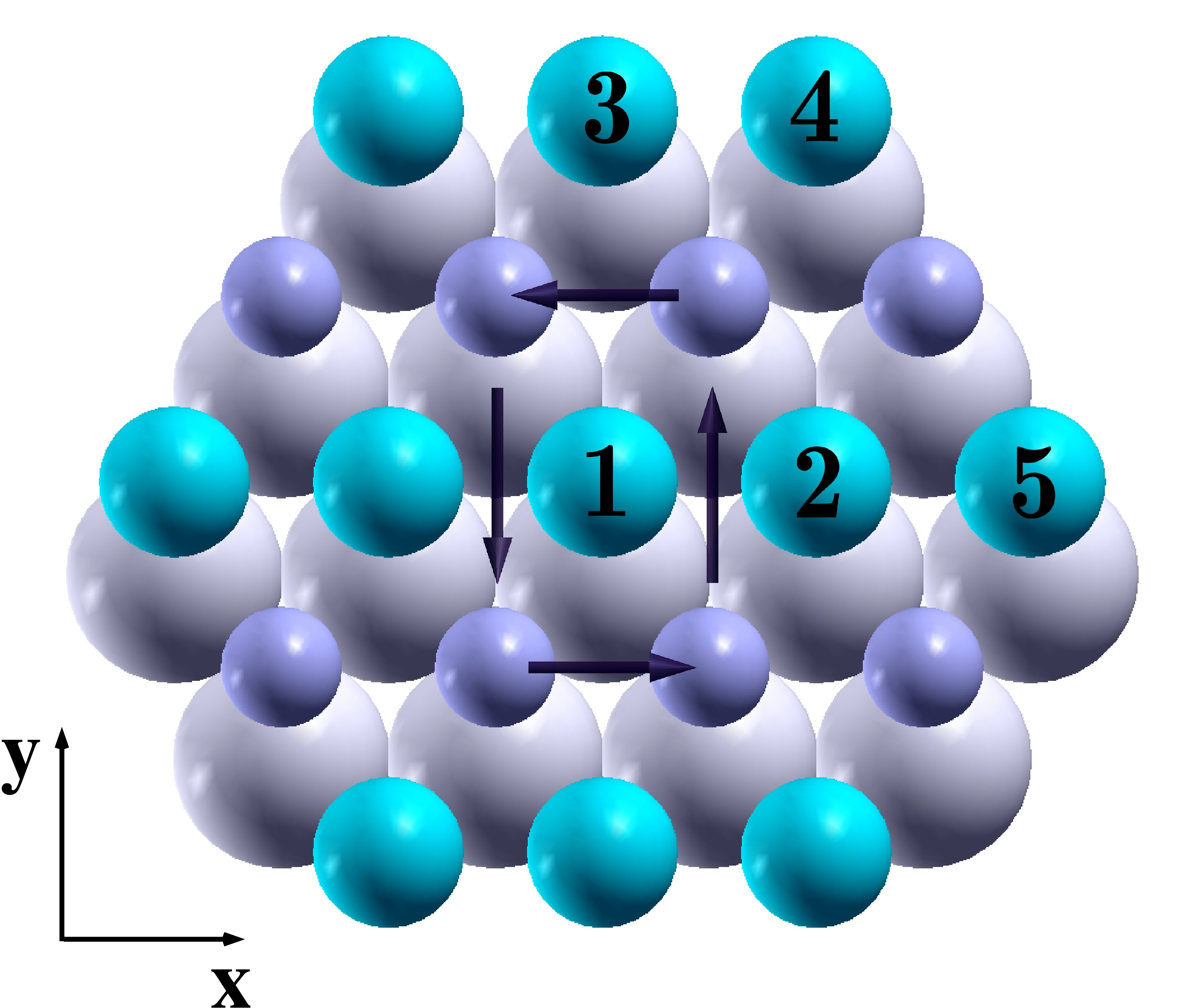
Despite the detailed theoretical investigations based on a phenomenological approach, a complete understanding of the conditions for the SkX appearance cannot be obtained without a detailed analysis of the microscopic origin of the exchange interactions (both, isotropic and anisotropic) and magneto-crystalline anisotropy (MCA), that needs a fully relativistic ab-initio description of the electronic structure of the systems under consideration. Therefore theoretical schemes based on relativistic density functional theory (DFT) MV79 are applied to a large extend in computational simulations to support these experimental efforts BHB+06 ; BHB+07 ; HBB08 . In the present work we focus on the first-principles investigation of the formation of the SkX state in a FePt () monolayer deposited on Pt(111), consisting of alternating Fe and Pt atomic chains with atoms occupying the Pt crystallographic positions. The geometry of the () FePt/Pt(111) system is depicted in Fig. 1 (a).
The magnetic properties of the () FePt/Pt(111) clusters have been recently studied both experimentally and theoretically HLK+09 ; MBM+09 , showing the presence of a pronounced non-collinear magnetic structure in the system. This structure is governed by the strong DM interactions as well as a specific atomic structure consisting of alternating Fe and Pt chains leading to comparable values of isotropic and DM exchange interactions between neighbouring Fe chains. Here we demonstrate that the extension of the cluster to a monolayer leads to the formation of the SkX state in the presence of an external magnetic field.
II Computational details
The - phase diagram of FePt/Pt(111) has been obtained performing Monte Carlo simulations using a standard Metropolis algorithm Bin97 and based on the extended Heisenberg model accounting for the SOC induced anisotropy of the exchange interactions. The corresponding Hamiltonian is given by:
| (1) | |||||
with the isotropic exchange coupling parameters , the local magnetic moment of atoms , the DM vector and the anisotropy constants accounting for the on-site magnetocrystalline anisotropy (MCA) energy associated with each individual moment oriented along .
The main results presented here are obtained taking into account only the exchange interactions between magnetic Fe atoms, neglecting the contribution from the Pt atoms having a small induced magnetic moment which gives a small correction to the critical temperature.
A fully relativistic approach for the calculation of the exchange interaction tensor based on the magnetic force theorem was used USPW03 . This gives access to the isotropic and DM exchange coupling parameters used in an extended Heisenberg model, Eq. (1).
The electronic structure calculations for a monolayer of FePt on Pt(111), denoted FePt/Pt(111), have been performed within the local density approximation for DFT VWN80 , using the spin-polarized relativistic Korringa-Kohn-Rostoker multiple scattering formalism Ebe00 . In this scheme, the Dirac Green function was calculated self-consistently for FePt/Pt(111) assuming pseudomorphic deposition on a Pt slab consisting of 37 atomic layers and having the experimental lattice constant of bulk Pt ( Å). All calculations have been performed within the atomic sphere approximation (ASA) to the potentials and lattice relaxations near the surface have been neglected (see Ref. BSM+12 for more details).
III DM interactions
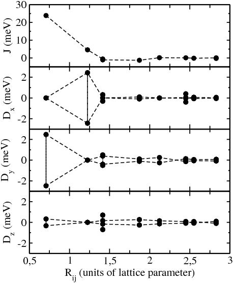
The structure of the () FePt/Pt(111) system is depicted in Fig. 1 (a) consisting of a monolayer of alternating Fe and Pt atomic chains deposited on a Pt(111) surface. The calculated magnetic moments of the Fe and Pt atoms within the FePt monolayer are , and , respectively. The induced magnetic moment in the Pt substrate decreases quickly away from the surface having and in the interface and next to the interface layers, respectively. Figure 1 (b) represents the isotropic exchange coupling parameters and and components of the DM interaction vector. These parameters for the FePt film on Pt(111) are very close to those obtained for the FePt/Pt(111) cluster MBM+09 (Note however the different form of the Heisenberg Hamiltonian used in MBM+09 , that leads to the exchange parameters being two times bigger per definition than those used in the present work). Strong interactions between the first neighboring Fe atoms indicate the favorite conditions for the appearance of a HM structure in the system. The properties of along different directions (Fig. 1 (b) and Table 1 are clearly governed by the system symmetry Mor60a ; CL98 . The symmetry plane between the in-chain Fe atoms 1 and 2 (see Fig. 1 (a)) forces the component along the chain to be equal to 0. The symmetry plane crossing the Fe atoms at positions 1 and 3 allows a non-zero component of interaction along the direction parallel to Fe and Pt chains. Summarizing the results for the DM interaction for other distances one can conclude that they have pronounced in-plane components (see Fig. 1) responsible for a rotation of the magnetic moments within a corresponding plane orthogonal to the film. As it follows from the model consideration by Fert and Levy FL80 giving the expression for DM interactions in the form ( correspond to the sites of magnetic atoms while corresponds to the sites of atoms mediating exchange interaction), the DM interactions are mediated by the Pt atoms and their big magnitude is essentially determined by strong SOC of the Pt atoms. This allows also to draw conclusions about the small contribution to the component of the DM vector at short distances , coming (i) from the substrate Pt atoms as well as (ii) from the Pt atoms within the FePt monolayer (this contribution is non-zero only in the presence of the Pt substrate responsible for the breaking of the inversion symmetry). On the other hand, the large magnitude of the and components is fully determined by the substrate Pt atoms, giving evidence to the crucial role of their strong SOC values for the in-plane components of the interactions between the Fe atoms. At large distances all three components have the same order of magnitude, due to contributions of many Pt atoms involved into the mediation of Fe-Fe DM exchange interactions. Thus, one can clearly see a pronounced SOC induced effect in the present system leading to DM couplings strong enough to compete with the isotropic exchange coupling and to create a pronounced non-collinear magnetic structure.
(a)
 (b)
(b)
| - | ||||||
|---|---|---|---|---|---|---|
| - | 0.707 | 0.00 | 2.44 | 0.39 | 23.90 | |
| - | 1.225 | -2.47 | 0.00 | 0.00 | 4.59 | |
| - | 1.414 | -0.31 | 0.50 | -0.69 | -0.56 | |
| - | 1.414 | 0.00 | 0.39 | -0.17 | -1.07 |
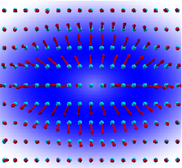
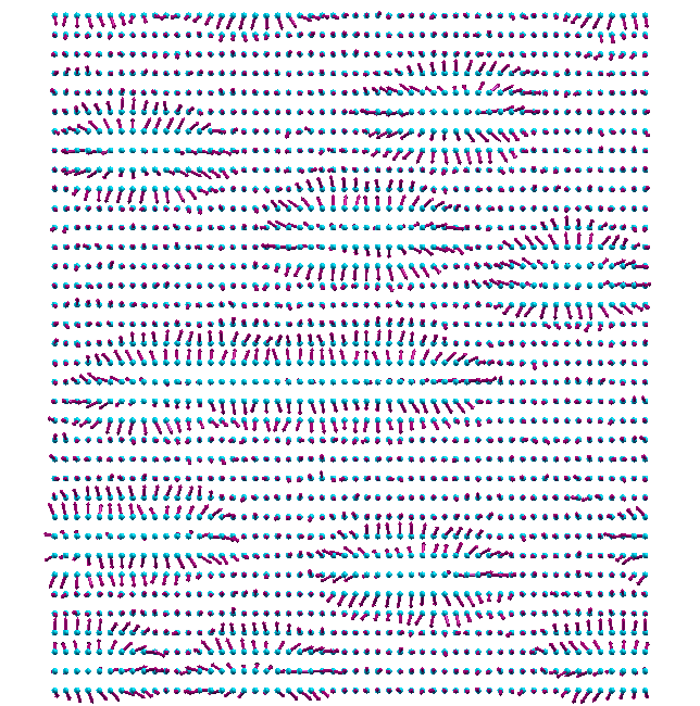
IV Helimagnetic structure
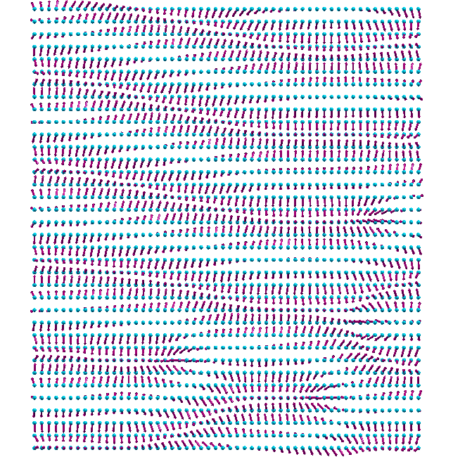
Magnetic torque calculations show a rather strong in-plane MCA of meV per Fe atom with the magnetic easy axis being perpendicular to the Fe and Pt chains. The MCA energy was taken into account in all present MC simulations based on Heisenberg Hamiltonian Eq. (1). First, the calculations have been performed in the absence of an external magnetic field. The resulting non-collinear magnetic structure obtained at K is presented in Fig. 2. The period of the helicity in the continual model represented by Landau-Ginzburg energy functional is determined by the ratio of exchange stiffness and Dzyaloshinsky-Moriya constants, BH94 . In general, these values are represented by tensors of first rank, , and second rank, LKG84 , characterizing a spatial anisotropy of the system, that is important for the present case having symmetry. In particular, these values give the anisotropy of the energy of spin-wave excitations with wave vector along different directions, : , with spin-wave coefficients and , and the spin-wave gap created by magnetocrystalline anisotropy.
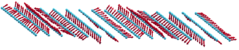
The strong anisotropy of the exchange stiffness tensor is well recognized considering the first-neighbor isotropic exchange coupling parameters (see Table 1) within and between the Fe chains. This leads to a complex HM structure with a different period along different directions, i.e. the period along the chains is essentially longer than perpendicular to the Fe chains, as can be clearly seen in Fig. 2. Raising the temperature from K, the magnetization of the system exhibits two phase transition: from HM to FM state at K, and from FM to the paramagnetic (PM) at K.
(a)
 (b)
(b)
 (c)
(c)
 (d)
(d)
V Skyrmion magnetic structure
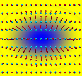
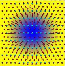
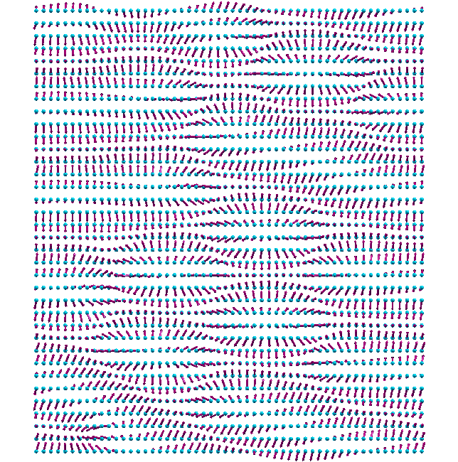
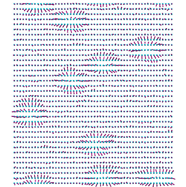
The presence of an external magnetic field perpendicular to the surface plane, exceeding a certain critical value, gives rise to the formation of Skyrmions in the system under consideration. The distribution of the magnetic moments within the single Skyrmion obtained using the MC simulation is shown in Fig. 3. The topological quantum number (or winding number) calculated for such a magnetic texture is equal to -1 (see Appendix), being a property of single Skyrmion (see, e.g.,MBJ+09 ; OOS+12 ) One can clearly see the rather small Skyrmion size (compared with the period of the HM structure) due to a small ratio. Its different size in two orthogonal directions within the plane is determined by the spatial anisotropy of the exchange coupling parameters, and . The in-plane tangential components of the magnetic moments governed by component of DM interactions are close to , in line with the discussions by Rößler et al. RLB10 on the magnetic moment distribution within the Skyrmions in FM system with symmetry.
Analyzing the requirements for the Skyrmion formation for FePt/Pt(111), one can use rather simple qualitative arguments. In this consideration the effect of a demagnetizing field can be neglected being small in the case of a magnetic monoatomic overlayer. A competition of isotropic exchange and DM interactions determine the period of the HM structure without magnetic field and anisotropy by minimizing the energy of the system. In the presence of an out-of-plane magnetic field the minimization of the Zeeman energy is realized by minimizing the 2D area with magnetic moments opposite to the direction of the magnetic field (the Zeeman energy gain is shown by yellow color, while the energy loss is shown by blue in Fig. 3 (a)). However, this costs the energy originating from the inter-atomic isotropic exchange, due to a non-collinear orientation of the in-plane components of the magnetic moments within the Skyrmion (see Fig. 3 (b), where the exchange energy loss is shown by blue color), assuming that the Skyrmion size is close to the period of the HM structure. The competition of these two factors determine the conditions for the formation of Skyrmions at some critical value of the external magnetic field . Despite the strong simplification neglecting the role of other contributions (due to exchange interactions and MCA) to the SkX energetics, this qualitative consideration visualizes the role of the magnetic field for the SkX formation as a ground state ( K), relevant in the case 2D system.
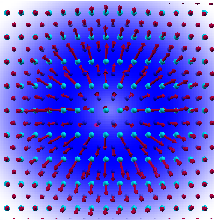
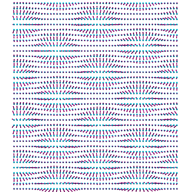
As was mentioned above, the 2D anisotropy of the system leads to a corresponding shape of the Skyrmions obtained via calculations accounting for Fe-Fe exchange interactions only, as soon as only Fe atoms carry spontaneous magnetic moments weakly dependent on magnetic configuration. Since isotropic exchange interactions between Fe atoms within the Fe chains are much stronger than the inter-chain Fe-Fe interactions, their competition with DM interactions results in the weaker modulation of magnetic structure along the chains when compared to the direction perpendicular to the chains. However, in systems containing atoms with induced magnetic moments, i.e., Pt in the present case, the Fe-Pt interactions, , can lead to an additional contribution to the Fe-Fe exchange energy if (shown in Fig. 1) value is not negligible (see discussions, e.g. Mry05 ; LME+06 ; PMS+10 ). However, to account for this contribution in MC calculations is not straight-forward and is rather time consuming. Therefore, we have performed here the calculations accounting for Fe-Pt interactions only to investigate their effect on the shape of the Skyrmion, following the scheme described in Ref. PMS+10 . Based on this, we conclude that the Pt contribution could modify the phase diagram, but these changes should not be crucial. The result, obtained at K, is presented in Fig. 3 (c). One can see that the Skyrmion shape in this case is more symmetric. This occurs due to an additional Fe-Pt exchange contribution competing with DM interactions and resulting in the increase of the effective J/D (see the above discussion) ratio along the direction perpendicular to the Fe chains, and leading that way to the increase of the Skyrmion size along the direction perpendicular to the Fe chains.
VI Phase diagram
(a)
 (b)
(b)
 (c)
(c)
 (d)
(d)
 (e)
(e)
 (f)
(f)
 (g)
(g)
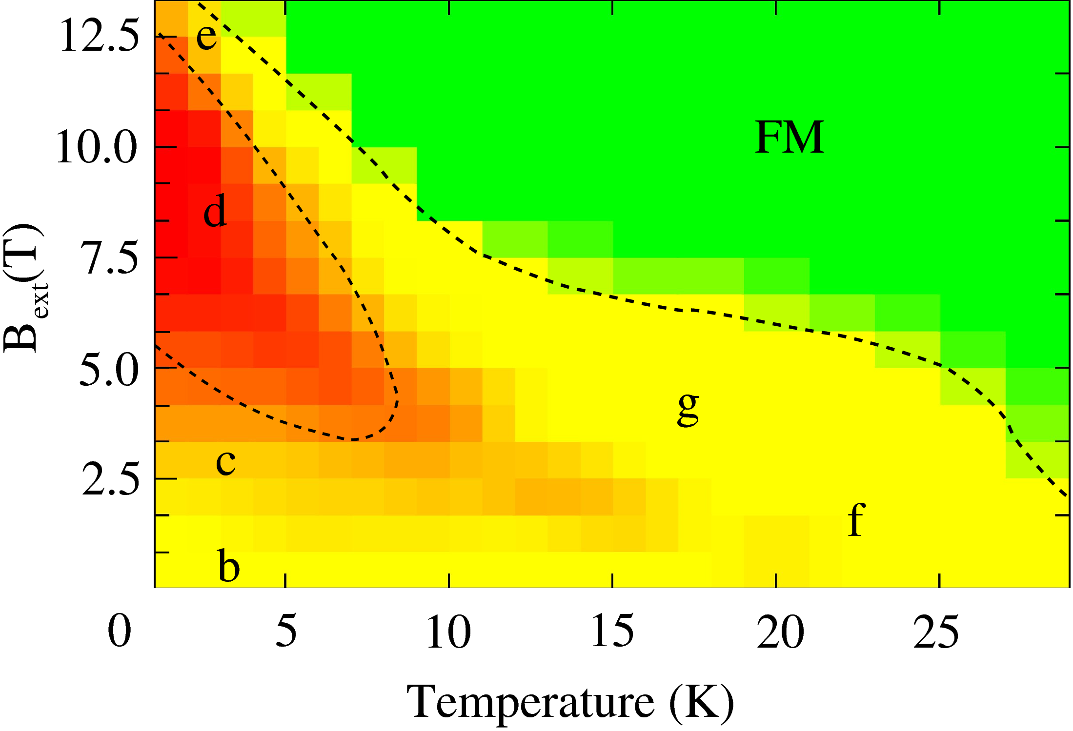
The magnetic structure of FePt/Pt(111) and its behavior at different temperature and external magnetic field, perpendicular to the surface, has also been investigated via Monte Carlo simulations, using the standard Metropolis algorithm. For this, only the interactions within the Fe subsystem with well defined local magnetic moments have been taken into account. The MC unit cell containing 2500 Fe atoms was extended using periodic boundary conditions. The in-plane magnetic anisotropy was taken into account with MCA direction perpendicular to Fe chains and meV (obtained in present calculations). The important role of the magnetic anisotropy for the stabilization of SkX state in some systems was discussed in the literature BLRB10 ; RLB11 . Therefore, a set of additional MC calculations has been performed for the out-of-plane MCA direction (with the MCA energy equal to 1.1 meV) as well as for the MCA energy set to 0. All these results exhibit rather small differences indicating a weak effect of the MCA and therefore the main responsibility of the exchange interactions (isotropic and DM) for the SkX stabilization in the system under consideration. Therefore, we present below only the results obtained for in-plane MCA found in the present DFT calculations.
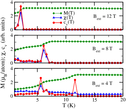
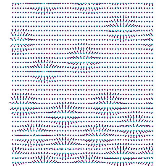
More results of the MC simulation can be seen in Fig. 4 representing the low-temperature part of the - phase diagram. The critical temperatures within the MC simulations have been obtained from an analysis of the heat capacity and susceptibility . Figure 5 shows the temperature dependence of these parameters for three different values of the magnetic field: T (top panel), T (middle panel) and T (bottom panel). In the first two cases the curves have only one maximum corresponding to the boundary of the SkX region, while the two maxima of in the case of T are associated with the low- and high-temperature boundaries of the SkX region shown in Fig. 4 in red. To improve the statistical error a series of independent calculations have been performed here for each point at the phase diagram: (i) by varying the temperature at a fixed magnetic field value and (ii) by varying the magnetic field, keeping the temperature constant. Nevertheless, one has to admit that perfect phase boundaries have not been obtained. As soon as the density of Skyrmions reproduces the SkX phase boundaries with the same accuracy as and , the phase diagram is plotted representing the density of Skyrmions at each point. Without magnetic field the system exhibits a rather pronounced SOC-induced HM structure (Fig. 4 (b)) below the critical temperature K. The FM structure is stabilized in the temperature region from K to K, while the following temperature increase drives the system into the PM state. The critical temperatures have been evaluated from the temperature dependent behaviour of the magnetic susceptibility, using the average magnetization in the system as an order parameter. An external magnetic field, , leads at low temperature to the formation of Skyrmions coexisting with the HM structure (Fig. 4 (c)). Raising of the magnetic field at low temperature leads to the formation of a Skyrmionic lattice (Fig. 4 (d)). The density of Skyrmions is shown in the phase diagram by red and yellow, representing the SkX area with highest Skyrmion density by red, while the wide region with low Skyrmion density is colored in yellow. Note that the boundary between the low Skyrmion (yellow) and FM (green) phases was plotted using only the data on the temperature dependence of Skyrmion density which is very low in this region. The dashed lines are drawn as a guide for the eyes to visualize the approximate boundaries separating different phases. At high magnetic fields and low temperature the concentration of Skyrmions is reduced resulting in the mixed FM + Sk state (Fig. 4 (e)) until the transition to the FM state. At these values of the magnetic field the transition to the FM + HM + Sk state does not occur. On the other hand, at high temperature and low magnetic field, as it was discussed above, a mixed FM + HM + Sk state is observed (Fig. 4 (f)), while an increasing of the magnetic field leads to a mixed FM + Sk state (Fig. 4 (g)). At all values of the magnetic field the temperature increase leads to a transition from the non-collinear magnetic state to the FM state.
Thus, the behavior of the magnetic structure of FePt/Pt(111) in the presence of a finite external field shows striking differences when compared with the properties of 3D systems, e.g. FeGe, MnSi, MnGe, etc. This is, first of all, due to the well defined Fe local magnetic moment indicating a small effect of longitudinal fluctuations on the formation of Skyrmionic magnetic properties. A Skyrmion lattice state in the phase diagram appears at low temperature, in contrast to 3D systems, where the Skyrmion lattice formation occurs close to the temperature of the transition to the disordered magnetic state. Because the Curie temperature in the system is rather high, the temperature increase leads first to the transition from the Skyrmionic to the FM state and then from the FM to the PM state, in contrast to the SkX-PM transition observed in the 3D bulk compounds FeGe, MnSi and MnGe. Finally, we would like to stress that strong in-plane components of the interactions, governed by the substrate Pt atoms in FePt/Pt(111), lead to a small Sk size (see above), that makes this system attractive for technological applications. Note however, that too strong DM interactions can lead to a stabilization of the SkX as a ground state HBM+11 ; LLZ11 , even without external magnetic field. One can expect different behavior of this state when compared to those discussed above, although detailed investigations of its phase diagram so far have not been done.
VII Acknowledgements
Financial support by the DFG via SFB 689 (Spinphänomene in reduzierten Dimensionen) is thankfully acknowledged.
VIII Appendix
To calculate the winding number for an isolated Skyrmion obtained within MC calculations, its magnetic configuration can be represented by a continuous model in cylindrical coordinates. In this case, the direction of the magnetic moment is equal to for each point in the (film) plane. Note that the in-plane component of the magnetic moment is always aligned along the radius : , and is an angle with respect to the axis, depending only on the distance from the center of the Skyrmion. In this case the winding number can be calculated by doing the necessary integration using polar coordinates:
| (2) | |||||
Taking into account the expressions for the derivatives in polar coordinates (see, e.g., VMK88 ) and assuming that and (where is the Skyrmion radius) one obtains the winding number according to the shape of the Skyrmion:
| (3) |
References
- (1) A. N. Bogdanov and U. K. Rößler, Phys. Rev. Lett. 87, 037203 (2001).
- (2) M. Lee, W. Kang, Y. Onose, Y. Tokura, and N. P. Ong, Phys. Rev. Lett. 102, 186601 (2009).
- (3) T. Schulz, R. Ritz, A. Bauer, M. Halder, M. Wagner, C. Franz, C. Pfleiderer, K. Everschor, M. Garst, and A. Rosch, Nature Physics 8, 301 (2012).
- (4) F. Jonietz, S. Mühlbauer, C. Pfleiderer, A. Neubauer, W. Münzer, A. Bauer, T. Adams, R. Georgii, P. Böni, R. A. Duine, K. Everschor, M. Garst, and A. Rosch, Science 330, 1648 (2010).
- (5) A. Neubauer, C. Pfleiderer, B. Binz, A. Rosch, R. Ritz, P. G. Niklowitz, and P. Böni, Phys. Rev. Lett. 102, 186602 (2009).
- (6) Y. Li, N. Kanazawa, X. Z. Yu, A. Tsukazaki, M. Kawasaki, M. Ichikawa, X. F. Jin, F. Kagawa, and Y. Tokura, Phys. Rev. Lett. 110, 117202 (2013).
- (7) A. N. Bogdanov and D. A. Yablonsky, Sov. Phys. JETP 68, 101 (1989).
- (8) A. Bogdanov and A. Hubert, J. Magn. Magn. Materials 138, 255 (1994).
- (9) U. K. Rößler, A. N. Bogdanov, and C. Pfleiderer, Nature 442, 797 (2006).
- (10) A. B. Butenko, A. A. Leonov, U. K. Rößler, and A. N. Bogdanov, Phys. Rev. B 82, 052403 (2010).
- (11) K. von Bergmann, S. Heinze, M. Bode, E. Y. Vedmedenko, G. Bihlmayer, S. Blügel, and R. Wiesendanger, Phys. Rev. Lett. 96, 167203 (2006).
- (12) M. Bode, M. Heide, K. von Bergmann, P. Ferriani, S. Heinze, G. Bihlmayer, A. Kubetzka, O. Pietzsch, S. Blügel, and R. Wiesendanger, Nature 447, 190 (2007).
- (13) M. Heide, G. Bihlmayer, and S. Blügel, Phys. Rev. B 78, 140403 (2008).
- (14) I. E. Dzyaloshinskii, Sov. Phys. JETP 19, 960 (1964).
- (15) C. Pappas, E. Lelièvre-Berna, P. Falus, P. M. Bentley, E. Moskvin, S. Grigoriev, P. Fouquet, and B. Farago, Phys. Rev. Lett. 102, 197202 (2009).
- (16) U. K. Roessler, A. A. Leonov, and A. N. Bogdanov, J. Phys. Chem. Solids 200, 022029 (2010).
- (17) N. S. Kiselev, A. N. Bogdanov, R. Schäfer, and U. K. Rößler, (2011).
- (18) S. Mühlbauer, B. Binz, F. Jonietz, C. Pfleiderer, A. Rosch, A. Neubauer, R. Georgii, and P. Böni, Science 323, 915 (2009).
- (19) X. Z. Yu, Y. Onose, N. Kanazawa, J. H. Park, J. H. Han, Y. Matsui, N. Nagaosa, and Y. Tokura, Nature 465, 901 (2010).
- (20) X. Z. Yu, N. Kanazawa, Y. Onose, K. Kimoto, W. Z. Zhang, S. Ishiwata, Y. Matsui, and Y. Tokura, Nature Materials 10, 106 (2011).
- (21) A. Bauer, A. Neubauer, C. Franz, W. Münzer, M. Garst, and C. Pfleiderer, Phys. Rev. B 82, 064404 (2010).
- (22) W. Münzer, A. Neubauer, T. Adams, S. Mühlbauer, C. Franz, F. Jonietz, R. Georgii, P. Böni, B. Pedersen, M. Schmidt, A. Rosch, and C. Pfleiderer, Phys. Rev. B 81, 041203 (2010).
- (23) J. H. Han, J. Zang, Z. Yang, J.-H. Park, and N. Nagaosa, Phys. Rev. B 82, 094429 (2010).
- (24) S. Heinze, K. von Bergmann, M. Menzel, J. Brede, A. Kubetzka, R. Wiesendanger, G. Bihlmayer, and S. Blugel, NatPhys 7, 713 (2011).
- (25) N. Romming, C. Hanneken, M. Menzel, J. E. Bickel, B. Wolter, K. von Bergmann, A. Kubetzka, and R. Wiesendanger, Science 9, 636 (2013).
- (26) A. H. MacDonald and S. H. Vosko, J. Phys. C: Solid State Phys. 12, 2977 (1979).
- (27) J. Honolka, T. Y. Lee, K. Kuhnke, A. Enders, R. Skomski, S. Bornemann, S. Mankovsky, J. Minár, J. Staunton, H. Ebert, M. Hessler, K. Fauth, G. Schütz, A. Buchsbaum, M. Schmid, P. Varga, and K. Kern, Phys. Rev. Lett. 102, 067207 (2009).
- (28) S. Mankovsky, S. Bornemann, J. Minár, S. Polesya, H. Ebert, J. B. Staunton, and A. I. Lichtenstein, Phys. Rev. B 80, 014422 (2009).
- (29) K. Binder, Rep. Prog. Phys. 60, 487 (1997).
- (30) L. Udvardi, L. Szunyogh, K. Palotás, and P. Weinberger, Phys. Rev. B 68, 104436 (2003).
- (31) S. H. Vosko, L. Wilk, and M. Nusair, Can. J. Phys. 58, 1200 (1980).
- (32) H. Ebert, in Electronic Structure and Physical Properties of Solids, Vol. 535 of Lecture Notes in Physics, edited by H. Dreyssé (Springer, Berlin, 2000), p. 191.
- (33) S. Bornemann, O. Šipr, S. Mankovsky, S. Polesya, J. B. Staunton, W. Wurth, H. Ebert, and J. Minár, Phys. Rev. B 86, 104436 (2012).
- (34) T. Moriya, Phys. Rev. 120, 91 (1960).
- (35) A. Crépieux and C. Lacroix, J. Magn. Magn. Materials 182, 341 (1998).
- (36) A. Fert and P. M. Levy, Phys. Rev. Lett. 44, 1538 (1980).
- (37) A. I. Liechtenstein, M. I. Katsnelson, and V. A. Gubanov, J. Phys. F: Met. Phys. 14, L125 (1984).
- (38) S. S. S. I. Y. T. Y. Onose, Y. Okamura, arXiv:1204.5009 (2012).
- (39) O. N. Mryasov, Phase Transitions 78, 197 (2005).
- (40) M. Ležaić, P. Mavropoulos, J. Enkovaara, G. Bihlmayer, and S. Blügel, Phys. Rev. Lett. 97, 026404 (2006).
- (41) S. Polesya, S. Mankovsky, O. Šipr, W. Meindl, C. Strunk, and H. Ebert, Phys. Rev. B 82, 214409 (2010).
- (42) U. K. Rößler, A. A. Leonov, and A. N. Bogdanov, J. Phys.: Condens. Matter 303, 012105 (2011).
- (43) Y.-Q. Li, Y.-H. Liu, and Y. Zhou, Phys. Rev. B 84, 205123 (2011).
- (44) D. Varshalovich, A. Moskalev, and V. Khersonskii, Quantum Theory of Angular Momentum: Irreducible Tensors, Spherical Harmonics, Vector Coupling Coefficients, 3 Nj Symbols (World Scientific Publishing Company, Incorporated, ADDRESS, 1988).