Micro Pixel Chamber with resistive electrodes
for spark reduction
Abstract
The Micro Pixel Chamber (-PIC) using resistive electrodes has been developed and tested. The surface cathodes are made from resistive material, by which the electrical field is reduced when large current is flowed. Two-dimensional readouts are achieved by anodes and pickup electrodes, on which signals are induced. High gas gain ( ) was measured using 55Fe (5.9 keV) source, and very intensive spark reduction was attained under fast neutron. The spark rate of resistive -PIC was only times less than that of conventional -PIC at the gain of . With these developments, a new MPGD with no floating structure is achieved, with enough properties of both high gain and good stability to detect MIP particles. In addition, -PIC can be operated with no HV applied on anodes by using resistive cathodes. Neither AC coupling capacitors nor HV pull up resisters are needed for any anode electrode. Signal readout is drastically simplified by that configuration.
keywords: Gaseous detector; Micropattern gaseous detectors (MSGC, GEM, THGEM, RETHGEM, MHSP, MICROPIC, MICROMEGAS, InGrid, etc), Micro pixel chamber
1 Introduction
The -PIC is one type of micro pattern gaseous detector (MPGD) [1, 2]. There is a dot of anode and a surrounded cathode for one pixel, and many of those are printed on substrate. Primary electrons in gas volume are drifted toward the anode, and those are multiplied by a gas avalanche mechanism due to higher electric field between anode and cathode. The -PIC can be operated around of gas multiplication, which enables us to detect the minimum ionized particle. However, if there are large energy deposits simultaneously, such as recoiled nuclei, discharge and spark probabilities are raised because of dense electrons called the ”Raether limit” [3, 4, 5]. Those are a critical problem for using MPGD in intense hadron experiments. The most promising strategy for overcoming the spark problem is to make the MPGDs using high resistive electrodes [6, 7]. In the early stages of our investigation, we tried to overcoat high resistivity materials on the cathode electrodes [8, 9]. However, the sparks could not be suppressed by those early prototypes. With the improvement of structure, separating the resistive cathode and pickup electrodes, both higher gaseous gain (more than ) and strong spark reduction were achieved. The spark probabilities have been checked using fast neutron as a high ionizing particle (HIP). Those developments provide spark-free MPGD, which can be operated even in a next generation hadron collision experiment, where both MIP detection and HIP tolerance are required.
2 Design of detector
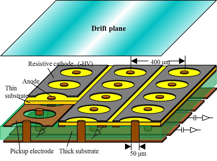
The structure of the new detector is based on -PIC [1, 2], which is one type of MPGD without floating structure, such as foils or mesh. Figure 1 shows a schematic structure of resistive cathode -PIC. The cathode electrodes are made from resistive material, instead of metal electrodes of existing -PIC. Huge current caused by spark or large energy deposits will reduce the electric field by higher resistive cathodes. Signals are read from both anodes and pickup electrodes. Those two types of readouts cross each other at right angles for detecting two-dimensional position. The pickup electrodes are placed along resistive cathodes below an insulating layer. The signals are induced on the pickup electrodes with capacitive coupling on the detector surface. In typical operation, static electrical field around the anode is quite the same as the existing -PIC (cathodes are made from metal). Positive ions produced by gas multiplication drift toward the cathodes, and signals are induced on both anodes and pickup electrodes. Meanwhile, if there are large energy deposits or discharges, the electrical potential of the cathode is raised due to movement of a large amount of charge. It reduces the electric field around the anode, and terminates the discharge immediately. Maximum charge of a spark will be limited by very small ( 0.1pF) capacitance of a single pixel.
3 Prototype production
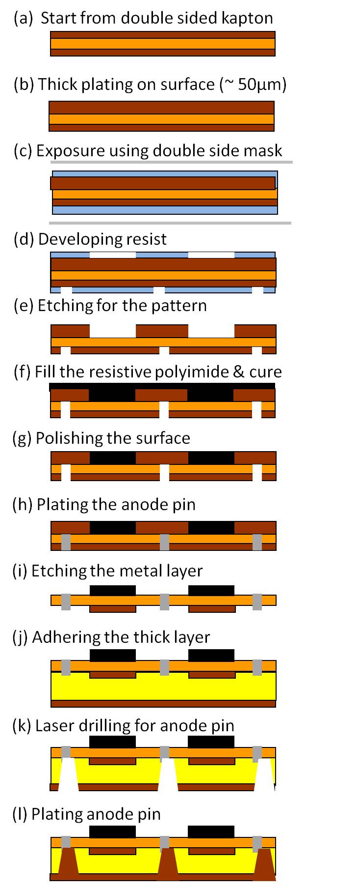
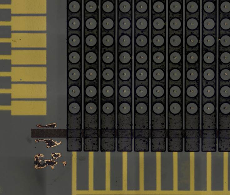
The prototype of the resistive cathode -PIC was made using carbon-loaded polyimide, provided by Toray Industries, Inc. To make the resistive strips (cathode strips), images of surface cathode patterns were first etched on the PCB board. The carbon-loaded polyimide was laid on the surface, and remaining surface metal was removed chemically after curing the polyimide. Figure 4 shows the manufacturing process of the resistive cathode -PIC. Those manufacturing processes were done by Raytech Inc. Our prototype has 10cm 10cm of detection area. The surface resistivity of the cathode strips is about 100 k/sq. - 10M/sq. Figure 4 shows a microscopic picture of the detector surface, and Figure 4 shows the magnified picture around one electrode.

4 Operation test
The gaseous gain of the prototype was checked using 55Fe source (5.9keV X-ray). Signals were observed from both anode and pickup strip. Signal lines were connected to ATLAS ASD [10] with analogue output as preamplifiers. The charges of the signals were measured by digital oscilloscope directly. The anodes and pickup signals have opposite signs but nearly identical charge in the same event. The gain curves were measured by the following four types of operation gases: Argon/ethane (7:3, 9:1) and Argon/CO2 (7:3, 9:1). A drift plane is set at a 3-mm gap from the -PIC board while applying voltage of -1 kV. Potential of the resistive cathodes was set to 0 V, and the anode voltage was changed for gain measurements. The maximum anode voltage was determined by spark starting limit; However, the spark current of this resistive chamber (around 100 nA) was very low compared with conventional -PIC (more than 1 A). Figure 5 shows the results of gain measurements using those gases. The maximum gas gain was attained at using Argon/ethane (7:3) mixture gas.

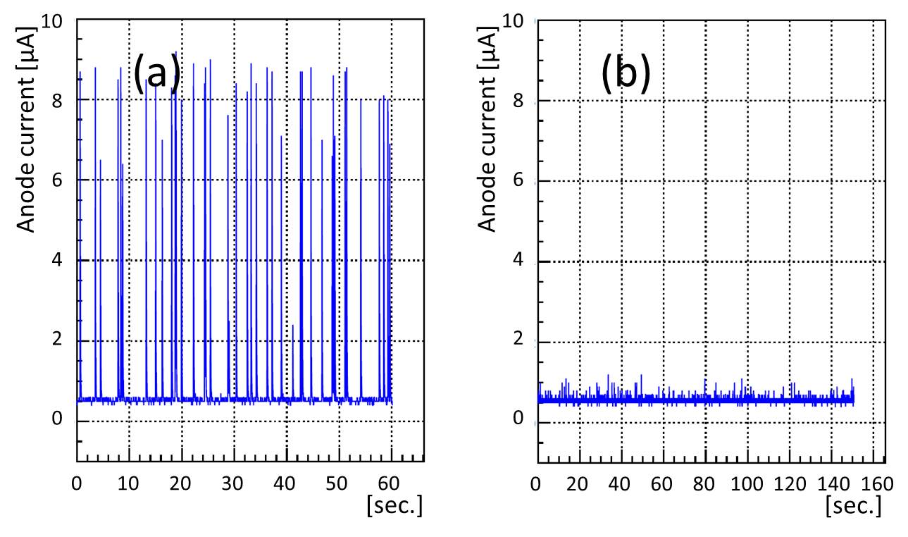
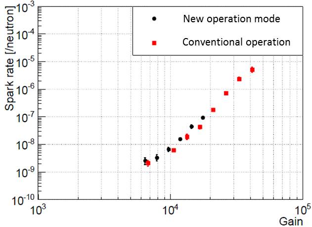
The spark tolerances in HIP were measured using fast neutron irradiation on the chamber [8]. A neutron source was provided by the tandem electrostatic accelerator at the Kobe University Faculty of Maritime Science (Fig. 6). The 3-MeV deuteron beam generated by this accelerator was guided to a beryllium target placed at the end of the beam line. The neutron was produced by a 9Be(d,n)10B exoergic (4 MeV) nuclear reaction. The peak neutron energy is estimated at 2.5 MeV. This facility can produce up to neutrons in a second. Figure 7(a) shows the output current monitor for existing -PIC with neutron/second irradiation, and Figure 7(b) shows resistive cathode -PIC with neutron/second irradiation. The gas gains of both setups were 15,000. We can see that the sparks were strongly suppressed, even with 900-times strong neutron. The spark rate is plotted in Figure 8 with the gas gain on the abscissa. This rate is defined as the ratio of huge sparks to the irradiated neutron numbers. The sparks were counted when the current monitor of the anode HV excess was 0.5 A and 2 A. Two resistive cathodes -PICs (named RC27/RC28 in the figure 8) and conventional -PIC were tested. From those measurements, sparks in the resistive cathode -PIC were reduced to -times smaller than those of conventional -PIC.


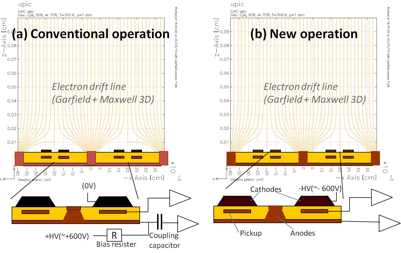
5 Novel Operation condition applying HV to resistive cathodes
In the conventional operation setup, positive HV was applied on anodes and the potential of cathodes was set to 0 V, to make a high electric field around the anode pixels. The coupling capacitors and bias resisters were required for each anode strip to read signals. On the other hand, the potentials of pickup electrodes and cathodes can be independent in resistive -PIC. Then, shifting the surface potentials, in which the anode potential is set to 0 V and resistive cathodes are applied negative voltage, is thought to work almost the same as the conventional setup. Neither decoupling capacitors nor bias resisters are needed on anodes. Pickup electrodes, as second coordinate signals, can also be connected to the readout directly. The capacitors and resisters for each electrode can be completely removed using this new operation. Difference between conventional and new operation modes is shown in Figure 9 with electron drift lines simulated using Garfield and Maxwell 3D. Both electron drift lines seem almost the same in those simulations.
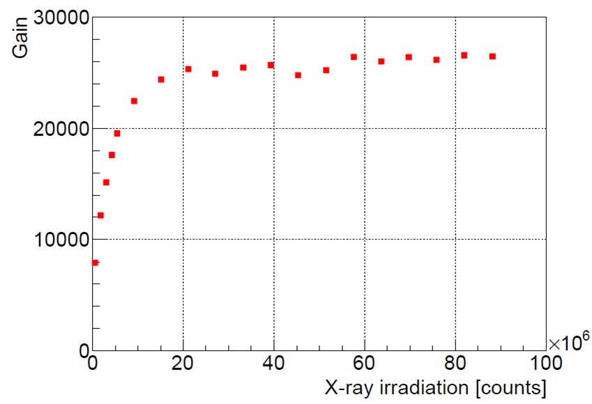
The gain curve and spark probabilities were measured in the new operation condition. The gain curve using Argon/ethane (7:3) mixture gas is shown in Figure 11. Operation voltage with the new operation was a bit greater than that with the conventional one. The time variability of the gain was found as shown in Figure 11. It is thought that this phenomenon is due to charge-up on the substrate. The gain became stable after counts/cm2 irradiation of incident 5.9keV (55Fe) X-ray source. The maximum gain and shape of gain curves were almost the same. As shown in Figure 12, spark probabilities under fast neutron were also almost the same.

6 Discussion and future prospects
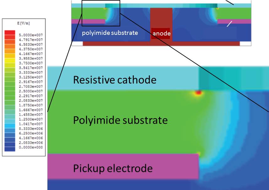
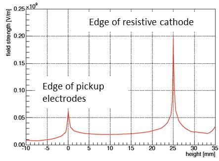
The results from section 5 show the new operation condition is performed as well as the conventional one. The new one has a great advantage in terms of detector production because fewer electronic parts are needed. However, there are problems remaining for stable operation. Sometimes the pickup electrodes have been shorted to resistive cathodes. Two of three of our prototypes have been broken in this phenomenon. The withstanding electric field of polyimide is around 300 kV/mm, and the substrate thickness (between resistive cathode and pickup) is 25m. The average electrical field in the substrate is estimated at around 20 kV/mm, which seems sufficiently lower than the withstanding field of polyimide. However, it is expected that the field at the edge of the electrodes will be higher. The electric fields around the cathode and pickup edge are simulated using Maxwell 3D as shown in Figure 14. Figure 14 shows the field strength along the line joining both the cathode and the pickup edge in Figure 14. The maximum field is about 200 kV/mm at the cathode edge, which is close to the withstanding field of polyimide. This simulation suggests that the margin of withstanding voltage is not sufficient. To improve it, thicker substrate will be used in the next prototype.
7 Conclusion
The Micro Pixel Chamber with resistive cathodes and capacitive readout was developed and tested. More than of gas gain was achieved stably, using 55Fe source under Argon/ethane (7:3) gas mixture. The spark rates were also measured using intense fast ( 2MeV) neutrons. The spark rate of resistive -PIC was strongly reduced. It was -times smaller than that of conventional -PIC at gain of . Using capacitive readout, the new operation mode, in which the two-dimensional signals can be read without HV coupling, was achieved. Although we need more improvements in the production process for stable operation, the resistive -PIC will be one of the best solutions for non-floating structure MPGD.
Acknowledgments
We thank Hideo Uehara in Reytech-Inc. whose diligent efforts contributed to our proposal and improved the fabrication process. Also we thank the RD51 members, especially Rui de Oliveira for many fruitful suggestions, and we also would like to thank the KEK Detector Technology Project and the Japan MPGD Basic R&D Team for their suggestions and technical supports. This research was supported by Grant-in-Aid for Scientific Research (No.23340072, 24654067).
References
- [1] A. Ochi, et al., Nucl. Instrm. Meth.A 471 (2001) 264
- [2] A. Ochi et al., Nucl. Instr. Meth.A 478 (2002) 196
- [3] H. Raether, Electron Avalanches and Breakdown in Gases. London, UK: Butterworth, 1964.
- [4] A. Bressan, et al., Nucl. Instr. Meth.A 424 (1999) 321
- [5] S. Bachmann, et al., Nucl. Instr. Meth.A 479 (2002) 294
- [6] R. Oliveira et al., IEEE Trans. on Nucl. Sci. Vol. 57, No. 6 (2010)
- [7] R. Oliveira et al., arXive:1101. 3727, (2011)
- [8] A Ochi, et al., Phys. Procedia 37 (2012) 554
- [9] A. Ochi, et al., JINST7(2012) C05005
- [10] ATLAS TGC Collaboration, Amplifier-Shaper-Discriminator ICs and ASD Boards, Production Readiness Review Report, 1999