THz-radiation production using dispersively-selected flat electron bunches
Abstract
We propose an alternative scheme for a tunable THz radiation source generated by relativistic electron bunches. This technique relies on the combination of dispersive selection and flat electron bunch. The dispersive selection uses a slit mask inside a bunch compressor to transform the energy-chirped electron beam into a bunch train. The flat beam transformation boosts the frequency range of the THz source by reducing the beam emittance in one plane. This technique generates narrow-band THz radiation with a tuning range between 0.2 - 4 THz. Single frequency THz spectrum can also be generated by properly choosing the slit spacing, slit width, and the energy chirp.
Accelerator-driven terahertz (THz) sources have attracted immense interest over a broad range of disciplines due to their ability to produce a high power, tunable radiation within compact footprintWen et al. (2013). Accelerator-based THz sources combine a sub-picosecond relativistic electron bunch with an electromagnetic radiative process, e.g., the beam could either pass through a foil radiator to emit coherent transition radiation (CTR) or travel through a dipole to emit coherent synchrotron radiation (CSR)Wu et al. (2013); Carr et al. (2002); Casalbuoni et al. (2009). The total spectral intensity of the emitted radiation from an electron bunch consisting of N electrons through a radiative electromagnetic process is given byNodvick and Saxon (1954):, where ( is the frequency), is the single electron spectral intensity and is the bunching factor, where is the the longitudinal time coordinate of the electron inside the bunch. Other broad-band THz schemes include advanced acceleration schemes such as laser-driven plasma acceleration and ion-driven accelerationGopal et al. (2013); Leemans et al. (2003). Narrow-band THz sources uses a variety of techniques such as corrugated waveguideBane and Stupakov (2012), emittance exchangerPiot et al. (2011), modulating the drive laser Shen et al. (2011); Boscolo et al. (2007), echo-basedDunning et al. (2012), or dielectric based Antipov et al. (2013) schemes. In this letter, we propose a simple scheme for THz generation using a slit mask in an dispersive region of a linear accelerator to generate up to 4 THz using a 50 MeV beam. The achievable frequency range span 0.2 - 4 THz. All this scheme requires is a photoinjector and a bunch compressor both of which are a standard components at almost all modern and planned future linear accelerators.
Magnetic bunch compressor are commonly incorporated in accelerators that drive free-electron lasers (FEL) to enhance the electron bunch peak current. Generating a train of sub-picosecond bunches using dispersive scraping in a chicane (four dipoles bending angle +,-,-,+) or in a dogleg (two dipoles separated by a drift) bunch compressor has been developed elsewhereNguyen and Carlsten (1996); Muggli et al. (2008).
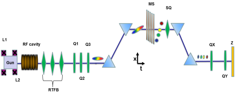
Figure 1 illustrate the principle of the proposed method. An electron beam is generated from a photoinjector and is then accelerated by a radio-frequency (RF) cavity. During acceleration, the electron beam gets an energy chirp - a time-dependent energy variation. The energy-chirped beam is then sent through a straight section of the linac that includes quadrupole magnets (Q1, Q2, Q3 in Fig. 1) and then to the bunch compressor. At the center of the bunch compressor, the bunch is intercepted by a slit mask (MS) which selectively scatters some of the electrons while other electrons are transmitted through the rest of the chicane. At the end of the chicane, such transversely separated beamlets are transformed into a train of short bunches longitudinally. The spacing between the bunches and the length of each bunch is determined by several factors such as the dispersion of the chicane (), the transverse betatron spot size of the beam at the mask, the width of the slit mask (), the uncorrelated relative beam energy spread () and the RF-energy chirp on the beam (). The formula that relates the length of the bunch at the exit of chicane to the width of the slit is given by Emma et al. (2004): , where is the output bunch length, is the longitudinal dispersion of the chicane, is the rms width of the mask, is the natural beam emittance, and is the betatron function at the mask. It can be seen that when is large, the output bunch profile follows the mask profile (). This can be done by making . For a chicane in our convention ( corresponds to the tail) , therefore by setting , the output bunch profile can be made to follow the mask profile. This technique is limited by the initial slice energy spread and emittance of the beam. We note that same function can also be reached by setting , which can become very large and impractical and in certain cases lead to overcompression. The above equation also indicates that to get a bunch train one should ensure that the betatron spot size at the slit mask is less than the slit width (). This can be done by properly setting the quadrupole magnet triplet (Q1, Q2, Q3) located upstream of the chicane to the right current setting. In order to reveal the longitudinal structure, the skew quadrupole (SQ) can be powered on that couples the x-dispersion into the y-plane and therefore the vertical () axis on the screen downstream is transformed into a time axisEmma et al. (2012). Finally, we note that this scheme allows for pulse shaping other than a train of pulses: for e.g. a triangular wedge shaped collimator can be used to generate ramped bunches that have application in advanced accelerator-type applications.
Hence, in our scheme the magnetic chicane effectively acts to decompress the bunch. By dispersing the beam inside the chicane, an correlation is introduced at the center of the chicane, where is the transverse position of the particle and its longitudinal position of the particle. Due to this high correlation, any variation in is then mapped onto . This scheme is different from Emma et al. (2004) where differential spoiling is used at high energy (few GeV) to generate femtosecond x-rays. Our scheme differs from it in two aspects: the low energy of our beam allows us to stop or scatter much of the beam using metallic slits and the bunch compressor is set to decompression. Also, our intrinsic relative energy spread is fairly high compared to that scheme because of the low energy of the beam. As mentioned above, our scheme differs from Muggli et al. (2008) by using a chicane instead of a dogleg and using the RF chirp as the tuning variable instead of using quadrupoles and an energy slit. We note that our scheme is more efficient since there is already an energy-chirp imparted naturally due to the longitudinal space-charge forces when the bunch exists the photoinjector that is favorable to our scheme (head is at high energy and tail is at lower energy) before it enters the RF cavity.
We show through tracking simulation that our scheme can generate tunable, coherent sub-THz (i.e around or less than 1 THz) radiation. The particle tracking program ELEGANTBorland (2000) was used for simulating the beam line. All the bending magnets are rectangular magnets. In all the simulation shown in this paper, CSR is taken into account. Nominal values for slit width and slit spacing along with the beam and chicane parameters are shown in Table. 1. The initial phase-space distributions are assumed to be Gaussian. A linear energy chirp is assumed to be imparted by the RF-cavity. This is a fairly good approximation considering we are operating far from the off-crest with a decompressing phase. We note that in a laboratory beam the phase-space out of the photoinjector might still be distorted and further simulations are planned to understand such effects.
| Parameter | Value | Units |
| Initial emittance (x,y) | 0.5 | |
| Beam energy | 50 | MeV |
| Initial slice energy spread | 5 | keV |
| Initial bunch length | 0.8 | mm |
| correlation (chirp) | [-10 … -4] | 1/m |
| Charge | 100 | pC |
| Slit spacing (center to center) | 1 | mm |
| Slit width | 50 | |
| Number of particles | 106 | n/a. |
| Dipole bending radius | 0.958 | m |
| Dipole length | 0.301 | m |
| Dipole angle | 18 | degrees |
| -18 | cm | |
| -30 | cm |
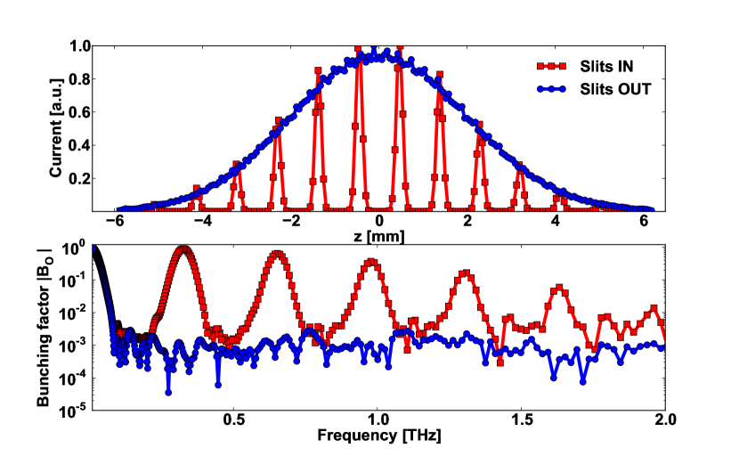
Figure 2 shows the current profile and the corresponding frequency spectrum from tracking simulation with and without the slits inside the beam line. When the slits are out, we get a single long, decompressed Gaussian bunch and the frequency spectrum obtained does not extend into the THz frequencies and is limited by the long bunch length. However when the slits are inserted, we obtain a train of short bunches and the frequency spectrum has a fundamental and its harmonics with a narrow bandwidth. The relationship between the number of bunches in a train, the period of the bunch train, the rms width of the bunch and the frequency spectrum is given in Piot et al. (2011). By tuning the RF-chirp on the electron beam prior to the chicane, the fundamental THz frequency can be tuned. The upper limit of the THz frequency is limited by the uncorrelated relative energy spread and the normalized emittance of the beam.
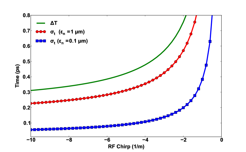
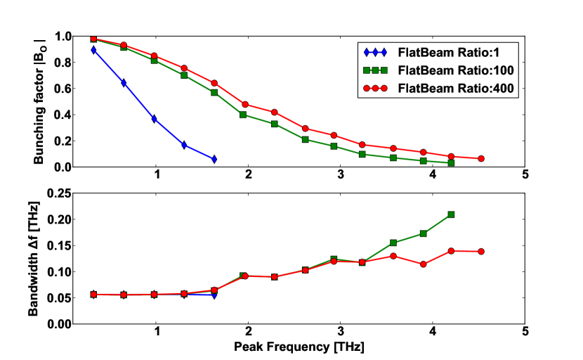
While the slit-based technique is capable of generating sub-THz frequencies, it is non-trivial to go above 1 THz without additional complexity. In order to go above the THz barrier, one needs smaller mask width but then the emittance requirement becomes challenging (). Figure 3 illustrates the effect of the normalized emittance on the formation of the bunch train for a given slit spacing. In order to get a bunch train, the spacing between the bunches () must be larger than the bunch duration of the individual bunches () (typically, ). The microbunch period is , where is the slits spacing, is the compression factor given by and is the speed of light. As shown in Fig. 3, lower emittance beam allows bunch train formation by producing shorter individual bunches for a fixed . One way to achieve low emittance would be to operate the linac at a lower charge (10 pC) but when going through the slits most of charge (upto 90%) could be lost. Another way to achieve low emittance in one plane only for e.g. in the horizontal plane is through flat-beam transformation. In order to generate a flat beam, the photocathode is immersed in an axial magnetic field which generates a magnetized electron beam. After acceleration, a set of three skew quadrupoles (RFBT in Fig. 1), is used to transform the magnetized beam into a flat beam. Such flat-beam transformation have been studied theoretically and demonstrated experimentally Brinkmann et al. (2001); Piot et al. (2006). A flat beam ratio of of 100 has been experimentally demonstrated at low energies using the Fermilab A0 photoinjector. Note the product of the emittances remains constant before and after the flat-beam transformation. Therefore, to achieve the required boost in the THz frequency and break the sub-THz barrier, we use flat-beam transformation in the linac. In order to demonstrate this, we use ELEGANT simulation. We use an emittance ratio of 100 and 400 which is consistent with simulationPiot et al. (2013a). The results shown in Fig. 4 indicates that the use of flat beam transformations helps to generate higher THz frequencies for a given slit spacing and width. The flat-beam transformation not only extends the maximum THz frequency but also improves the bunch form factor at lower frequencies as well. A scan over various emittance ratio and RF-chirp shows that frequencies as high as 4 THz can be obtained. In a superconducting linac, the RF-chirp can be controlled in a very precise manner with longitudinal feedback systems. Thus combining flat-beam technique, which can be done in any modern photoinjector linac using appropriate skew quadrupole magnets and a chicane equipped with a transverse mask, we can generate tunable multi-THz frequencies. In order to extract the THz radiation outside the beam pipe, we use a quadrupole doublet (QX, QY) followed by a CTR aluminium foil (Z shown in Fig. 1). Our simulation shows that a rms (round) spot size of =0.2 mm on both planes can be obtained at the screen using the doublet. This implies an upper cut-off frequency due to the transverse spot size of of 23 THz which is well above our highest frequency of our scheme (=100 at 50 MeV ).
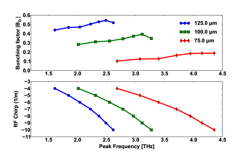
While both the fundamental frequency and its harmonics are present in the bunch due to the flat-beam transformation, sometimes only a single THz frequency might be preferred by users. This can be done by choosing the appropriate slit spacing and the width and supplying the correct RF-chirp. Figure 5 shows the effect of varying the slit-spacing (D) by choosing smaller-width slits (20 ) and RF-chirp. For this simulation, all other parameters remaining constant (Table. 1), a flat beam ratio of =1:400 was used Piot et al. (2013a). Proper choice of slit-spacing and RF-chirp allows a tunable range of 1-4 THz with a single frequency THz spectrum. A movable plate mounted with slits of different width and different spacing can easily be accommodated in a stepper motor controlled actuator to add this useful feature to the machine.
In summary, we have proposed and investigated via computer simulations a THz generation scheme that combines dispersive selection with flat electron beams. The advantage of this technique is its simplicity, tunability and low cost. The scheme does not require any additional hardware such as lasers, undulator, transverse deflecting cavity. Our scheme can be readily deployed in any linac that uses low energy compression such as ASTA Piot et al. (2013b), FLUTENasse et al. (2013). By using low emittance beam via flat-beam transformation in only one plane, tunable THz source covering 0.2 - 4 THz can be achieved. This scheme is also scalable to any superconducting linac as the only requirement is that the slit material should be able to withstand the heat load due to the multi-pulse structure of the electron bunch. Currently, experiments are planned at Fermilab’s ASTA facility using this scheme and we anticipate this technique to be useful for other accelerators.
We would like to thank M. Borland for his support in ELEGANT simulation. One of us (J. T.) would like to thank Randy-Thurman Keup for clarifying issues on THz detection. The work was supported by the Fermi Research Alliance, LLC under the U.S. Department of Energy.
References
- Wen et al. (2013) H. Wen, K.-J. Kim, A. Zholents, J. Byrd, and A. Cavalleri, Review of Scientific Instruments 84, 022501 (2013).
- Wu et al. (2013) Z. Wu, A. S. Fisher, J. Goodfellow, M. Fuchs, D. Daranciang, M. Hogan, H. Loos, and A. Lindenberg, Review of Scientific Instruments 84, 022701 (2013).
- Carr et al. (2002) G. Carr, M. Martin, W. McKinney, K. Jordan, G. Neil, and G. Williams, Nature 420, 153 (2002).
- Casalbuoni et al. (2009) S. Casalbuoni, B. Schmidt, P. Schmüser, V. Arsov, and S. Wesch, Phys. Rev. ST Accel. Beams 12, 030705 (2009).
- Nodvick and Saxon (1954) J. S. Nodvick and D. S. Saxon, Phys. Rev. 96, 180 (1954).
- Gopal et al. (2013) A. Gopal, S. Herzer, A. Schmidt, P. Singh, A. Reinhard, W. Ziegler, D. Brömmel, A. Karmakar, P. Gibbon, U. Dillner, T. May, H.-G. Meyer, and G. G. Paulus, Phys. Rev. Lett. 111, 074802 (2013).
- Leemans et al. (2003) W. P. Leemans, C. G. R. Geddes, J. Faure, C. Tóth, J. van Tilborg, C. B. Schroeder, E. Esarey, G. Fubiani, D. Auerbach, B. Marcelis, M. A. Carnahan, R. A. Kaindl, J. Byrd, and M. C. Martin, Phys. Rev. Lett. 91, 074802 (2003).
- Bane and Stupakov (2012) K. Bane and G. Stupakov, Nucl. Instrum. Methods. Phys. Res. A 677, 67 (2012).
- Piot et al. (2011) P. Piot, Y.-E. Sun, T. J. Maxwell, J. Ruan, A. H. Lumpkin, M. M. Rihaoui, and R. Thurman-Keup, Applied Physics Letters 98, 261501 (2011).
- Shen et al. (2011) Y. Shen, X. Yang, G. L. Carr, Y. Hidaka, J. B. Murphy, and X. Wang, Phys. Rev. Lett. 107, 204801 (2011).
- Boscolo et al. (2007) M. Boscolo, M. Ferrario, I. Boscolo, F. Castelli, and S. Cialdi, Nucl. Instrum. Methods. Phys. Res. A 577, 409 (2007).
- Dunning et al. (2012) M. Dunning, C. Hast, E. Hemsing, K. Jobe, D. McCormick, J. Nelson, T. O. Raubenheimer, K. Soong, Z. Szalata, D. Walz, S. Weathersby, and D. Xiang, Phys. Rev. Lett. 109, 074801 (2012).
- Antipov et al. (2013) S. Antipov, C. Jing, P. Schoessow, A. Kanareykin, V. Yakimenko, A. Zholents, and W. Gai, Review of Scientific Instruments 84, 022706 (2013).
- Nguyen and Carlsten (1996) D. Nguyen and B. Carlsten, Nucl. Instrum. Methods. Phys. Res. A 375, 597 (1996), proceedings of the 17th International Free Electron Laser Conference.
- Muggli et al. (2008) P. Muggli, V. Yakimenko, M. Babzien, E. Kallos, and K. P. Kusche, Phys. Rev. Lett. 101, 054801 (2008).
- Emma et al. (2004) P. Emma, K. Bane, M. Cornacchia, Z. Huang, H. Schlarb, G. Stupakov, and D. Walz, Phys. Rev. Lett. 92, 074801 (2004).
- Emma et al. (2012) P. Emma, F. Zhou, Z. Huang, and C. Behrens, Proceedings of the Free Electron Laser Conference (2012).
- Borland (2000) M. Borland, Advanced Photon Source LS-287 (2000).
- Brinkmann et al. (2001) R. Brinkmann, Y. Derbenev, and K. Flöttmann, Phys. Rev. ST Accel. Beams 4, 053501 (2001).
- Piot et al. (2006) P. Piot, Y.-E. Sun, and K.-J. Kim, Phys. Rev. ST Accel. Beams 9, 031001 (2006).
- Piot et al. (2013a) P. Piot, C. Prokop, B. Carlsten, D. Mihalcea, and Y. Sun, Proceedings of the International Particle Accelerator Conference (2013a).
- Piot et al. (2013b) P. Piot, V. Shiltsev, S. Nagaitsev, M. Church, P. Garbincius, et al., (2013b), arXiv:1304.0311 [physics.acc-ph] .
- Nasse et al. (2013) M. J. Nasse, M. Schuh, S. Naknaimueang, M. Schwarz, A. Plech, Y.-L. Mathis, R. Rossmanith, P. Wesolowski, E. Huttel, M. Schmelling, and A.-S. Muller, Review of Scientific Instruments 84, 022705 (2013).