Unfolding Orthogrids with Constant Refinement
Abstract
We define a new class of orthogonal polyhedra, called orthogrids, that can be unfolded without overlap with constant refinement of the gridded surface.
1 Introduction
An unfolding of a polyhedron is obtained by cutting the surface of the polyhedron and flattening it in the plane as a simple non-overlapping polygon. An edge unfolding considers only cuts made along edges, while general unfoldings allow cuts anywhere on the surface.
A polyhedron is orthogonal if each of its faces is perpendicular to a coordinate axis. An orthogonal polyhedron cannot be unfolded using edge cuts alone (the simplest example is a box sitting on top of a larger box). A grid unfolding of a polyhedron allows additional cuts along grid edges created by slicing with axis-aligned planes that pass through at least one polyhedron vertex, which we refer to as grid planes. Few nontrivial subclasses of orthogonal polyhedra are known to have grid unfoldings: orthotubes [BDD+98], orthostacks composed of orthogonally convex slabs [DM04], well-separated orthotrees [DFMO05] and terrains [O’R07].
A -refined grid unfolding, defined for an orthogonal polyhedron and for some integer , allows additional cuts created by at most planes parallel to and sandwiched between adjacent grid planes. A remarkable breakthrough is the -refined grid unfolding of any orthogonal polyhedron homeomorphic to a sphere, where is polynomial in the number of polyhedron vertices [DDF12]. For constant , only two classes of orthogonal polyhedra are known to have a -refined grid unfolding: orthostacks [BDD+98], and Manhattan towers [DFO08].
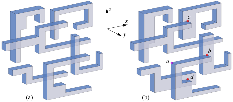
Informally, an orthogonal polyhedron is an orthogrid if it is composed of extrusions of simple polygons (which we call slabs) stacked together so that a (left) vertex belongs to a unique slab. It turns out that this restriction forces adjacent slabs to cross each other and collectively form a (non-uniform) orthogonal grid structure, hence the name of “orthogrid”. See ahead to Fig. 1 for two orthogrid examples.
Our Result.
In this paper we introduce a new class of orthogonal polyhedra, called orthogrids, and show that orthogrids have a -refined grid unfolding for some constant integer . Our restriction to orthogrids is necessary to guarantee that some front/back surface piece is available at each vertex, so it can be used in unfolding as needed.
2 Definitions
Let be an orthogonal polyhedron with the surface homeomorphic to a sphere (i.e., genus zero). Classify the faces of according to the direction of their outward normal: front (), back (), top (), bottom (), right () and left (). The vertices of fall into similar categories, with the difference that a top or bottom vertex is also a left or right vertex, depending on its two incident faces. We take the -axis to define the vertical direction; vertical faces are parallel to the -plane or the plane. Clockwise (cw) and counterclockwise (ccw) directions are defined with respect to a viewpoint at . The gridded version of adds edges to the surface of by intersecting with planes parallel to Cartesian coordinate planes through every vertex. We distinguish between an original vertex of the polyhedron, which we call a corner vertex or simply a vertex, and the points of the grid (some of which may be vertices).
Let be planes passing through every vertex of , orthogonal to the -axis. By convention, is the plane with the largest -coordinate. Layer is the portion of bounded by planes and , and is composed of one or more connected components called slabs. The front (back) face of a slab is the face with normal pointing in the () direction, and it may be partly on the surface of and partly interior to . The top, right, bottom and left faces surrounding a slab form a band. The intersection between a band and a bounding plane is a cycle of edges called a rim, which we denote by . Each band in a layer has two rims, and . We use the notation to denote the closed area enclosed by rim . (Note that is either the front or the back face of the slab surrounded by .) Two bands and separated by a plane are adjacent if there is a point common to and .
If a vertex belongs to single slab of , then is called exposed; otherwise, is unexposed. In the example from Fig. 1b for instance, vertex is exposed, but vertices , and are unexposed.
Orthogrids.
A genus zero orthogonal polyhedron is an orthogrid if all left vertices of are exposed. We further assume that has no y-dents, meaning that each -perpendicular 2D cross section of has genus zero. Note that the meaning of “left” in the definition of an orthogrid is tied to a coordinate system, therefore a polyhedron with all right vertices exposed is also an orthogrid (simply reverse the direction of the -axis). Fig. 1 shows two examples of orthogrids: one with all vertices exposed (a), and one with some right vertices unexposed (b).
3 Preliminary: Single Band Unfolding
Single band unfolding is a basic tool used in several unfolding papers [DFO07, DFO08, DDF12]. The key idea is to identify a path on the box surface that cycles around the top, right, bottom and left faces of the box at least once, and can be flattened out into an -monotone orthogonal path in the plane. We refer to this path as the unfolding spiral, or simply the spiral; we denote the spiral on the box surface , and the flattened version of the spiral in the plane .
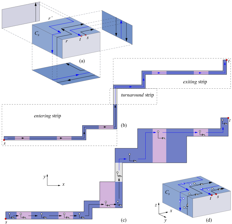
Figure 2a shows the directed path followed by : it starts at the entering point on the top edge of the front rim and spirals in clockwise direction around the top, right, bottom, and left faces toward the back rim . We call this spiral strip from up to the point it hits the entering strip. We require that the entering strip cycles around the band at least once, before moving towards the back rim . When it reaches , turns around by crossing the back face upwards toward the top edge of ; we refer to this back face strip as the turnaround strip, to emphasize its role in the unfolding. From , the unfolding path spirals in a counterclockwise direction back to , ending at the exiting point lying next to on the front rim. We call this strip piece extending from back to the exiting strip. Thus the entering strip and the exiting strip spiral in opposite directions.
When is cut out, unfolded and laid horizontally in the plane, it forms a monotonic staircase as depicted in Fig. 2b. The spiral can be subsequently thickened so that it covers the top, right, bottom and front faces entirely, as depicted in Fig. 2c. Marked along the flattened spiral path in Fig. 2d is an L-shaped indicator (or simply an -indicator) with two pointers corresponding to the coordinate axes in the plane: the hand pointer pointing in the direction of the positive -axis, and the head pointer pointing in the direction of the positive -axis. When mapped back onto the 3D box shape, the -indicator traces the path taken by . This makes it easier to visualize the orientation of just by looking at the -indicator on : if the -indicator glides in the direction of the hand pointer along a piece of , that piece flattens out horizontally to the right in the plane; if the -indicator glides in the direction opposite to the hand pointer along a piece of , that piece flattens out horizontally to the left in the plane. This is what we will try to avoid (with small exceptions) so that maintains its -monotonicity. If the -indicator glides in a direction orthogonal to the hand pointer along a piece of , that piece flattens out vertically in the plane. In this latter case, the up or down direction is irrelevant, because we seek monotonicity only in the horizontal direction. For this reason, we will henceforth refer to the -indicator as Hand, to remind the reader that it is really the hand pointer that affects the monotonicity property of . Nevertheless, the head pointer will be useful in tracing the paths taken by the unfolding spiral on the surface of . In Fig. 2d for example, one can imagine the Hand sliding across the surface in the direction indicated by the arrows; the head pointer is simply an aid in this visualization process.
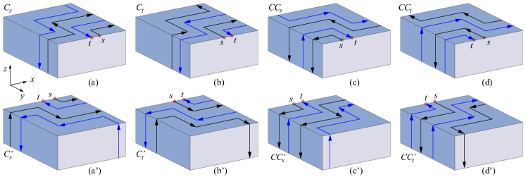
The type of unfolding depicted in Fig. 2 and again in Fig. 3a is denoted by . The symbol is used to indicate that the entering strip starts on the front rim of the band and cycles clockwise around the band. The subscript is used to indicate that the (black) entering strip (rather than the (blue) exiting strip) runs alongside the rim containing and ; the only place it doesn’t run alongside the rim is at the small gap at where the exiting spiral leaves the band. Sometimes the unfolding of a band will be required to begin on the back rim of ; we use the symbol to indicate that the unfolding begins on the back rim. The unfolding is simply an -reflection of the unfolding, and is depicted in Fig. 3a′. The only difference between and is that and are located on the front rim in the first case, and on the back rim in the latter case; the fact that the entering strip starts by making a clockwise cycle around the rim containing applies to both cases.
Alternate types of unfolding are (Fig. 3b), (Fig. 3c), (Fig. 3d), and their corresponding primed -reflections (Fig. 3b′), (Fig. 3c′) and (Fig. 3d′). Here the symbol () is used to indicate that the entering strip starts on the front (back) rim of the band and cycles counter-clockwise around the band; and the subscript is used to indicate that the (blue) exiting strip runs alongside the rim containing and (with the exception of the small gap between and ).
For ease of reference we introduce the following definitions. The band rim containing the entering point is called the entering rim; the opposite band rim is called the turnaround rim, to indicate the fact that the turnaround is executed on the facet of that rim. Note that, if the unfolding type for a band is or , the entering rim is the front rim and the turnaround rim is the back rim; and if the unfolding type is or , then the entering rim is the back rim and the turnaround rim is the front rim.
Call the strip that runs alongside the front rim of a band the front strip. Note that the front strip could be either on the entering spiral or on the exiting spiral. Similarly, call the strip that runs alongside the back rim of a band the back strip. The unfolding directions of the front and back strips corresponding to the eight unfolding types depicted in Fig. 3 are summarized in Table 1.
| Unfolding Label | Front Strip | Back strip |
|---|---|---|
| Clockwise, on entering spiral | Counterclockwise, on exiting spiral | |
| Counterclockwise, on exiting spiral | Clockwise, on entering spiral | |
| Counterclockwise, on exiting spiral | Clockwise, on entering spiral | |
| Clockwise, on entering spiral | Counterclockwise, on exiting spiral | |
| Counterclockwise, on entering spiral | Clockwise, on exiting spiral | |
| Clockwise, on exiting spiral | Counterclockwise, on entering spiral | |
| Clockwise, on exiting spiral | Counterclockwise, on entering spiral | |
| Counterclockwise, on entering spiral | Clockwise, on exiting spiral |
4 Overview of Unfolding Algorithm
Observe that in the case of an orthogrid, any two adjacent bands exhibit a left face orthogonally crossing a top face of the other band. (This is because all left vertices of an orthogrid are exposed.) Our unfolding algorithm uses this property in transitioning from one band to the other and back. The overall structure of the unfolding algorithm is as follows:
-
1.
Compute a band unfolding tree . Select the root of to be a band of smallest y-coordinate, with ties broken arbitrarily (§5).
-
2.
Determine forward and return transition paths corresponding to each arc in , and assign an unfolding label to each band in (§6.3).
-
3.
Starting with the root band, unfold each band as a conceptual unit, but interrupt the unfolding each time a forward transition path to a child is encountered. The unfolding follows the forward transition path to the child band, the child band is recursively unfolded, then the unfolding returns along the return transition path back to the parent, resuming the parent band unfolding from the point it left off. The resulting strip is laid out horizontally in the plane (§9).
-
4.
Attach the vertical front and back faces of below and above appropriate horizontal sections of the unfolding strip determined in the previous step (§10).
We proceed to presenting the details of each of these steps.
5 Computing an Unfolding Tree
The unfolding tree has one node for each band and anchors connecting pairs of adjacent bands as follows. For each band and each band adjacent to , we add arc to and select the anchor point connecting to to be the leftmost topmost intersection point between and . It can be verified that the structure constructed this way os a tree that spans all bands.
To distinguish edges in from edges of the orthogonal polyhedron , we will refer to the first as arcs, and to the latter simply as edges. A child is a front child (back child) if it is adjacent to the front (back) of its parent.
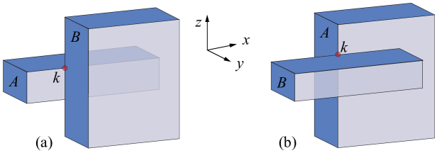
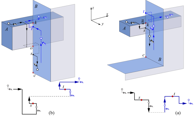
An anchor connecting a parent band to a child band falls in one of the following two categories:
-
(C1)
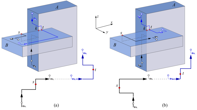
The anchor is a point at the intersection between a horizontal edge of and a vertical edge of (see Fig. 4a). We call a C1-anchor, and a C1-child.
-
(C2)
The anchor is a point at the intersection between a vertical edge of and a horizontal edge of (see Fig. 4b). We call a C2-anchor, and a C2-child.
6 Unfolding Tools
In this section we present three key tools used in implementing the recursive unfolding procedure sketched in §4: forced turns (§6.1), unfolding variations (§6.2) and forward and return transition paths (§6.3). In the unfolding procedure of , we say that a band has been visited if an unfolding path has been traced on by Hand. We seek to maintain two invariants throughout the unfolding procedure:
-
(I1)
The Hand is parallel to the -axis on a horizontal face of a band, pointing in the direction of the unfolding.
-
(I2)
If a vertical rim edge of a band contains at least one anchor point attaching an unvisited child of to , then the Hand is parallel to the -axis (pointing to either or ) while moving along .
As we shall shortly see, invariant (I2) enables recursive unfolding of ’s children attached to .
6.1 Forced Turns
Invariants (I1) and (I2) will sometimes require the Hand to change orientation when moving from a horizontal face to a vertical face of a band, or vice-versa. Such a reorientation corresponds to a -turn of the strip in the plane. (Recall that is the flattened plane version of the unfolding strip .) We call such reorientations forced turns, to distinguish them from the normal turns resulting from the basic unfolding method described in §3.
Forced turns will be executed only at left vertices of , which by definition are exposed. Let be a convex vertex of a band where a forced turn occurs. The turn for the case when the Hand is on a horizontal (vertical) face of upon meeting is depicted in Fig. 5a(b), for both (left) and (right). The coordinate axes from Fig. 5a indicate that the top left vertex is encountered in a counterclockwise traversal of the band; however, a simple reorientation of the coordinate axes shows that this turn also applies to the case when is a bottom left vertex encountered in a clockwise band traversal.
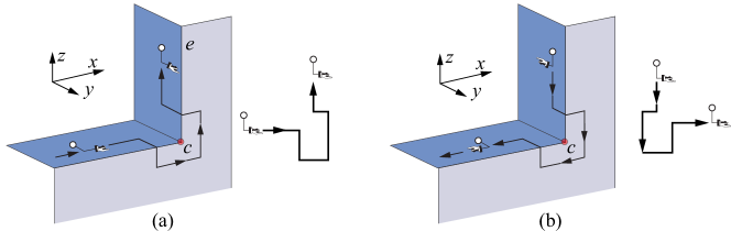
Fig. 6 a(b) shows the forced turn for the case where is a reflex vertex, and the Hand is on a horizontal (vertical) face of upon meeting . Note that the paths traced by in Fig. 6 are not monotone in the -direction, but the extent of the turn steps are adjusted so that does not self-intersect (the steps can be arbitrarily small, but are exaggerated in the figure for the sake of clarity). The forced turns depicted in Figs. 5a and 6a indicate that the following property holds:
Property 1
Also observe that the clockwise/counterclockwise unfolding direction is the same before and after a forced turn. This is necessary so that the unfolding advances along the path depicted for the single band in §3, rather than backtracking. To make it possible for vertical-to-horizontal turns to also preserve the unfolding direction, we require one more invariant to be maintained throughout the unfolding procedure:
-
(I3)
Each vertical-to-horizontal forced turn at a corner vertex reorients the Hand parallel to the -axis, pointing in the the unfolding direction. Just before a vertical-to-horizontal turn is forced at a vertex , the Hand points toward the -plane containing if is convex (Fig. 5b), and away from the -plane containing if is reflex (Fig. 6b).
Note that the vertical-to-horizontal turns depicted in Figs. 5b and 6b for are mirrors of the corresponding horizontal-to-vertical turns from Figs. 5a and 6a, with the unfolding direction reversed. Also note that each horizontal-to-vertical forced turn results in the Hand pointing in a direction opposite to the one required to perform the counterpart vertical-to-horizontal turn (compare Figs. 5a and 5b, and similarly for Figs. 6a and 6b). As we shall later see, a horizontal-to-vertical turn at a corner vertex of a band is performed only if an unvisited child of is attached to the vertical edge of incident to (so a forced turn is necessary to maintain invariant I2). This will enable us to use one such unvisited child to reverse the direction of the Hand if necessary.
Throughout the paper, the terms reverse and opposite associated with a vector indicate the scalar multiplied by .
6.2 Unfolding Variations
In this section we present one variation to the basic unfolding types presented in §3, to accommodate for the fact that sometimes the unfolding of a band must begin on a vertical face of the band. We refer to the unfolding types depicted in Fig. 3 as -unfoldings, to indicate the fact that the unfolding starts and ends with the Hand parallel to the -axis. We introduce a variation called -unfolding, which begins and ends with the Hand parallel to the -axis (see ahead the entering and exiting hand in ’s unfolding from Fig. 8).
Consider an unfolding that starts on a vertical face of a band, with the Hand parallel to the -axis (see starting point marked in Fig. 7). Let be the first vertex encountered by the Hand during the unfolding. Our discussion for the rest of this section is based on the assumption that invariant (I3) holds, meaning that upon reaching , the Hand is oriented in such a way that a forced turn at maintains the unfolding direction. After the forced turn, the unfolding spiral follows the same path as in the case of an -unfolding, up to the point where the exiting strip reaches vertex on its return trip. At this point the exiting strip retraces the path taken by the entering strip around and along the vertical face incident to .
Fig. 7 shows the retracing path around a convex vertex (the reflex vertex case is similar). Note that the nesting of the unfolding strips around matches the nesting of the strips on the incident band faces, so no crossing occurs. Also note that turns taken in opposite directions at also have opposite Hand orientations on both incident (vertical and horizontal) band faces.
We remind the reader that the extent of the turn steps are exaggerated for clarity in our figures, but in fact the turns can be made arbitrarily close to the corner vertex. Similarly, the entering and exiting point can be placed arbitrarily close to each other. The following property will be crucial in proving the correctness of the unfolding algorithm.
Property 2
The entering Hand and the exiting Hand on a band have opposite orientations.
6.3 Transition Paths and Unfolding Labels
Corresponding to each arc in connecting a parent band to a child band , we select two transition paths: a forward transition path from to , and a return transition path from back to . When the unfolding strip for reaches a forward transition path to an unvisited child , the unfolding follows this path to , band is recursively unfolded, then unfolding follows the return transition path back to . Each of these two transitions must maintain invariants (I1)-(I3). In addition, the return transition must be executed in such a way that the unfolding of can be resumed at the point it left off, as if the interruption did not occur. In other words, the orientation of the Hand on following the return transition must be identical to the one on prior to the forward transition. This section is concerned with determining the forward and return connecting paths corresponding to each arc in , and assigning an unfolding label to each band in that is consistent with these transitions.
Consider an arbitrary arc connecting parent band to child band . Let be the plane separating and . In the following we discuss the transitions between and corresponding to each of the two anchor classes.
6.3.1 C1-Transitions
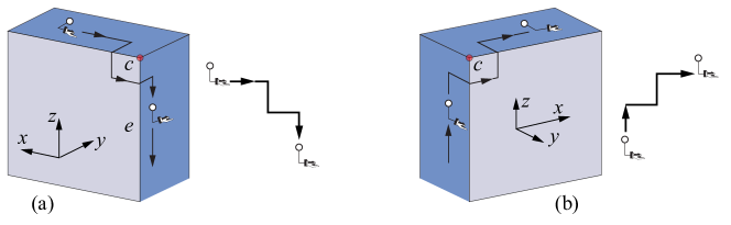
In this case the anchor connecting child to parent is a point at the intersection between a horizontal edge of and a vertical edge of , as depicted in Fig. 4a. Consider first the case in which the unfolding proceeds clockwise along the top edge of upon reaching . By invariant (I1), the Hand is parallel to the -axis on the top edge of . Let be the vertical edge of incident to . After the forward transition to , the Hand must be parallel to the -axis on (so that invariant (I2) is satisfied in case unvisited children of are attached along ) and pointing in the direction required by invariant (I3).
The forward transitions from to are depicted in Fig. 8 (follow the paths from to in the direction indicated by the arrows, ignoring for the moment the return transition paths from to ). The forward transition depends on the nature of the bottom endpoint of :
-
1.
If is convex, then the Hand must point toward upon reaching (invariant I3). This is accomplished by the forward transition depicted in Fig. 8a. (Flattened spiral is shown below .) Note that the transition uses a second point at the at the intersection between and on the open vertical segment , to flip the orientation of the Hand. The intersection point always exists, because the left vertex is exposed (by the definition of an orthogrid).
-
2.
If is reflex, then the Hand must point away from upon reaching (invariant I3); this property is enforced along the entire edge segment by the forward transition depicted in Fig. 8b ( shown below ).
For the cases depicted in Fig. 8, the entry and exit points for are selected so that they support a recursive -unfolding of ; these points are marked in Fig. 8 for each situation identified above. Note that upon exiting at , the Hand is parallel to the -axis and pointing in the direction opposite to the one used upon entering at (by Property 2). This enables the unfolding strip to make the complementary return transition from back to depicted in Fig. 8 (follow the return path from to in the direction of the arrows). Note that each of these return transitions preserve the orientation of the Hand on as required by invariant (I3).
Our discussion so far was based on the assumption that the unfolding proceeded clockwise along the top edge of before reaching . This assumption helps visualize the transitions between the and , however the transitions are general: the case when the unfolding strip proceeds counterclockwise on upon meeting is similar to the clockwise case, with forward and return path switching roles and traversed by the Hand in opposite direction.
Next we assign an unfolding label to consistent with the transitions discussed above. The label we assign to depends on whether is a front or back child of . We discuss three related cases; the unfolding labels for the second and third case will be derived from the unfolding label established in the first case.
| Anchor Class | Child | Unfolding label for | Unfolding label for |
|---|---|---|---|
| C1 | front | , , , or | (Figs. 8a,b) |
| (front strip clockwise) | |||
| , , , or | |||
| (front strip counterclockwise) | |||
| back | , , , or | ||
| (back strip clockwise) | |||
| , , , or | |||
| (back strip counterclockwise) |
Case 1.
is a front child of and the front strip of runs clockwise just before reaching . We assign to the label to indicate the fact that ’s unfolding starts at the back of , and the entering strip runs alongside the back rim of in counterclockwise direction. Note that this label is consistent with the transitions from Fig. 8.
Case 2.
is a front child of and the front strip of runs counterclockwise just before reaching . Then the same transitions as in Case 1 occur, with the forward and return transition strips switching roles and traversed by the Hand in opposite direction. Note that the direction opposite to the one indicated by the return strip matches the direction of the forward strip, therefore the unfolding direction is as established for the clockwise case (Case 1). The only change in the unfolding label from Case 1 is switching indices and , to indicate a switch in the roles of the entering and exiting strips. Thus the unfolding label for is .
Case 3.
is a back child of . Note that an -mirror of Cases 1 and 2 above depicts the case in which is a back child of ; this transformation preserves the unfolding direction and the notion of left/right, but reverses the notion of front/back. Consequently, ’s unfolding label for the case when the back strip runs clockwise (counterclockwise) just before reaching can be obtained from ’s unfolding label for the case when the front rim runs clockwise (counterclockwise) just before reaching , by replacing by . See Table 2 for a summary of all unfolding labels.
6.3.2 C2-Transitions
C2-transitions apply when the anchor connecting an unvisited child of parent is a point at the intersection between a vertical edge of and a horizontal edge of , as depicted in Fig. 4b. By invariant (I2), the Hand is parallel to the -axis upon reaching . After making the forward transition to the horizontal face of , the Hand must be parallel to the -axis, so that invariant (I1) is satisfied. We now show how to execute such a transition.
-
1.
If the Hand on points toward , then the forward transition from to uses a small L-shaped strip from the front/back face of containing , as depicted in Fig. 9a. (Follow the path from to in the direction of the arrows, ignoring for the moment the return path from to .) Note that Fig. 9 depicts only the case where is a front child and the unfolding proceeds clockwise along . However, we will see that all other cases can be derived from this case.
-
2.
If the Hand on points away from , then the forward transition from to is similar to the transition from the previous case, with the unfolding going in opposite direction on . The transition for this case is depicted in Fig. 9b.
Each of these forward transitions positions the Hand parallel to the -axis on a horizontal face of , so invariant (I1) is satisfied. By Property 2, the Hand will be parallel to the -axis after an -unfolding of , pointing in the direction opposite to the one upon entering . This property enables the return transitions from to depicted in Fig. 9.
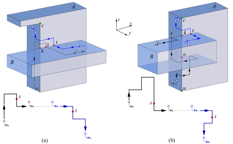
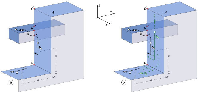
We will see that the unfolding algorithm (discussed later in §9) may sometimes require a C2-child band to flip the orientation of the Hand for the parent band, so that it is properly positioned for an upcoming forced turn (as required by invariant I3). In this case, both forward and return transitions are slightly different. Let be the corner vertex of such that is on the rim of and extends from in the unfolding direction of . By invariant (I3), a Hand reversal may be necessary in two situations: (i) if the Hand points toward and is reflex, and (ii) if the Hand points away from , and is convex. The forward and return transitions for case (i) are depicted in Fig. 10a ( at the top and at the bottom), and enable an -unfolding of . In case (ii) we use in the transition to a small neighborhood around a second point at the intersection between and , as depicted in Fig. 10b. The intersection point always exists, because all left vertices are exposed (by the definition of an orthogrid). Note that the return transitions from Fig. 10 reverse the orientation of the Hand on , as required.
Figs. 9 and 10 depict the situation in which the unfolding proceeded clockwise on upon reaching . The case when the unfolding strip proceeds counterclockwise on upon meeting is similar to the clockwise case, with forward and return path switching roles and traversed by the Hand in opposite direction. Finally, a vertical -mirror of the above cases depicts the situation in which is a back child of .
We are now ready to assign an unfolding label to consistent with the transitions identified in this section. Recall that ’s label depends on the unfolding direction and the orientation of the Hand on . As in the case of the C1 anchor class, here we discuss the situation where is a front child of and the front strip of runs clockwise just before reaching the anchor attaching to ; all other cases are symmetric. If the Hand points towards as it reaches (as depicted in Fig. 9a), we assign to the label to indicate the fact that ’s unfolding starts at the back of in counterclockwise direction, and the entering strip runs alongside the back rim of . Note that this label is consistent with the transitions from Fig. 9a. If the Hand points away from as it reaches (as depicted in Fig. 9b), we assign to the label to indicate the fact that ’s unfolding starts at the back of in clockwise direction, and the exiting strip runs alongside the back rim of . This label is consistent with the transitions from Fig. 9b.
| Anchor Class | Child | Unfolding label for | Hand orientation on | Unfolding label for |
|---|---|---|---|---|
| C2 | front | , , , or | Towards anchor | (Figs. 9a) |
| (front strip clockwise) | Away from anchor | (Fig. 9b) | ||
| , , , or | Towards anchor | |||
| (front strip counterclockwise) | Away from anchor | |||
| back | , , , or | Towards anchor | ||
| (back strip clockwise) | Away from anchor | |||
| , , , or | Towards anchor | |||
| (back strip counterclockwise) | Away from anchor |
The unfolding labels for the situation when is a front child of and the front strip of runs counterclockwise just before reaching are derived from the unfolding labels for the situation discussed above, with and switching roles (because the forward and return transition strips switch roles). Finally, the cases where is a back child of are -mirrors of the corresponding cases with as a front child, and the unfolding labels can be obtained by simply dropping the prime symbol to indicate that ’s unfolding starts on the from rim of . The unfolding labels for all cases are listed in Table 3.
7 Unfolding a Child Band
Later in §9 we will define our main unfolding procedure Unfold for a band . This procedure unfolds and all its descendants in the unfolding tree , starting at entering point on and ending at exiting point on . We assume that the Hand is already positioned at entering point on at the beginning of the Unfold procedure, and the clockwise/counterclockwise direction of is determined by ’s unfolding label. After recursively unfolding all descendants of in (details to be filled in later), the procedure ends at with the Hand pointing in the direction opposite to the one indicated by the entering Hand.
In this section we make use of this Unfold procedure and the tools developed in the previous section to recursively unfold a child of a parent band , as described in the algorithm UnfoldChild from Table 4. The case when is a C2-child that must reverse the direction of the Hand on is handled by the procedure UnfoldChildReverse defined in Table 5.
UnfoldChild(Parent Band , Child Band ) Let be the anchor point connecting to the rim of If is a C1-child of Let be the corner vertex of such that is vertical and crosses Execute forward C1-transition (Fig. 8a for convex, Fig. 8b for reflex) Unfold() Execute return C1-transition (Fig. 8a for convex, Fig. 8b for reflex) If is a C2-child of Execute forward C2-transition as in Fig. 9a (9b) if Hand points to (away from) Unfold() Execute return C2-transition as in Fig. 9a (9b) if Hand points to (away from) Mark visited
UnfoldChildReverse(Parent Band , C2-child Band ) Let be the anchor point connecting to . Execute forward C2-transition as in Fig. 10a (10b) if Hand points to (away from) Unfold() Execute return C2-transition as in Fig. 10a (10b) if Hand points to (away from) Mark visited
8 Unfolding Rim Children
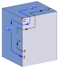
Having developed the procedure to recursively unfold a single child of a parent band , we now proceed to unfolding all children anchored to a rim of a band , as described in the UnfoldRimChildren algorithm from Table 6. This procedure will be invoked for both the entering and the turnaround rim of . In the case of the turnaround rim of , the UnfoldRimChildren procedure may need to handle one special child marked turnaround by the main unfolding procedure. This happens when has children anchored to , so a vertical strip from may be unavailable for the turnaround (as in the single box unfolding discussed in §6.2). In this case one particular child of attached to will be charged with reversing the unfolding direction of . (Note that the unfolding strip resulting from the recursive unfolding of plays the role of the turnaround strip in the single band unfolding from Fig. 2b.) Let UnfoldChildRetrace be a procedure identical to UnfoldChild, but with each return transition modified so that it retraces the forward transition. The result is that the Hand reverses its direction on the parent band. This procedure will be used in unfolding turnaround children.
At the start of the UnfoldRimChildren procedure, the Hand can be on a horizontal face of parallel to the -axis (by invariant I1), or on a vertical face of parallel to the -axis or the -axis (by invariant I2). The Hand begins cycling around , and processes three types of events that occur during this cycle. The actions taken in response to each of these events are summarized in Table 6. Next we discuss the details of each event.
UnfoldRimChildren(Band A, Rim r) Proceed with the Hand sliding along in the direction indicated by ’s unfolding label. While cycling around , process the following events: Let be the band face of that the Hand is currently on. Let be the edge of on the rim . Let be the corner vertex of that will be next encountered by the Hand. Let () be the other face of (edge of ) incident to If the hand indicator is about to pass the corner vertex /* Event 1 */ If ( is horizontal and there are unvisited children of attached to ) OR ( is vertical and the Hand is parallel to the -axis) Execute a forced turn at . If the Hand reaches an anchor attaching an unvisited child of to /* Event 2 */ If is marked turnaround, then UnfoldChildRetrace(, ) Else If is a C1-child of then UnfoldChild(, ) Else If is a C2-child of /* is vertical, is horizontal */ If (no unvisited child of is anchored on ) AND (Invariant I3 is violated by the Hand orientation relative to ) UnfoldChildReverse(A, B) Else UnfoldChild(A, B). If there are no more unvisited children of attached to /* Event 3 */ If is horizontal, then exit. If is the first rim of visited OR is the turnaround rim of If the Hand is parallel to the -axis, proceed to then force a turn at . Else proceed in the direction of the Hand to , then exit.
Event 1.
The first type of event occurs when the Hand reaches a corner vertex of . Let and be the two faces of incident to , with the Hand currently on . At this point, the Hand is about to make a transition from to . If is horizontal, then the Hand is parallel to the -axis. If the vertical rim edge incident to contains no anchor points attaching an unvisited child of , then no action is taken: ’s unfolding proceeds onto , with the Hand parallel to the -axis. Otherwise, if contains at least one anchor point attaching an unvisited child of , then the Hand must be reoriented parallel to the -axis on , so that the invariant (I2) holds. This is accomplished by a forced turn at .
If is vertical, invariant (I2) tells us that the Hand may be parallel to the -axis or to the -axis. In the first case, no action is necessary: the Hand continues to , where it becomes parallel to the -axis, so invariant (I1) is maintained. In the latter case, one of the forced turns depicted in Figs. 5b and 6b must be taken at , depending on whether is convex or reflex. By invariant (I3), such a forced turn at reorients the Hand parallel to the -axis, pointing in the unfolding direction. Thus invariant (I1) is maintained.
If this is the first time that gets encountered by the Hand, then the unfolding strip marks the first forced turn at . It is however possible that this is the second time the Hand encounters while positioned parallel to the -axis; this situation occurs when the unfolding of starts at a point on and there are children attached to on both sides of (see Fig. 11). In this case the Hand simply traces the path taken by the first forced turn at , so that it becomes parallel to the -axis on .
In the example from Fig. 11, the anchor point that attaches to its parent is located on the vertical edge of . The unfolding of begins at point located on the vertical segment just below , and proceeds downwards with the Hand parallel to the -axis; children attached to by anchor points located on the rim segment are recursively unfolded as they are encountered on the way down to . A forced turn is taken at corner vertex to reorient the Hand parallel to the -axis. Now note that there may be other children of attached to by anchor points located on the rim segment above . These children get visited as the unfolding strip moves downwards from , after a forced turn at that reorients the Hand parallel to the -axis. Once the unfolding strip passes on the way down to , it simply retraces the path previously taken around , until it reaches the the next horizontal face of . At this point, the unfolding strip has visited all children of and the UnfoldRimChildren procedure terminates.
Event 2.
The second type of event occurs when the Hand reaches an anchor attaching an unvisited child of . At this point the parent band unfolding is suspended and is recursively unfolded. If is a turnaround child, the unfolding direction of is reversed; otherwise the unfolding resumes on from the point it left off. If is a C2-child, then the decision whether must reverse the orientation of the Hand on so as to satisfy invariant (I3) must be taken at this point.
Event 3.
The third and final type of event occurs when all rim children of have been visited. In this case it may be necessary to proceed to the closest horizontal face of , to ensure that the Hand ends up parallel to the -axis. This is necessary if the unfolding strip needs to follow the unfolding path towards the other rim of (as in the single box unfolding from S6.2) in order to complete the unfolding of .
9 Main Unfolding Algorithm
In this section we describe the algorithm for recursively unfolding a band and all its descendants. Let be a band to unfold, initially the root band. The unfolding of begins at entering point and follows the basic unfolding path tied to ’s unfolding label, as discussed in §6.2. Let be the rim of containing , and let be the opposite (turnaround) rim of . The procedure Unfold from Table 7 describes our method for recursively unfolding all children attached to the band , starting at the entering point on . In the following we briefly discuss this procedure.
Unfold(Band ) Let be the entering rim and the turnaround rim of . If ’s unfolding label if of type : 1 Proceed with the Hand pointing in the direction indicated by ’s unfolding label. 2 UnfoldRimChildren(, ) 3 Move in the -direction toward (see box unfolding, §3). 4 If no children of are attached to Turn around by moving vertically across the facet (see box unfolding, §3). Else Proceed in the direction of the Hand up to the first child of anchored on . (If is a C2-child, a forced turn is taken at the last vertex encountered before ). Reassign ’s unfolding subscript to , so that it matches ’s unfolding subscript. UnfoldChildRetrace(, ) /* turnaround executed here */ UnfoldRimChildren(, ) Retrace unfolding path on back to If ’s unfolding label is of type : 5 From , move parallel to the -axis toward , then make a full cycle around . 6 Move in the -direction toward (see box unfolding, §3). 7 If no children of are attached to Turn around by moving vertically across the facet (see box unfolding, §3). Else Let be the child of anchored on that would be last encountered in a cycle around , starting from the current Hand position. Mark turnaround. Reassign ’s unfolding subscript to to match ’s subscript. UnfoldRimChildren(, ) 8 Retrace unfolding path on back to . 9 UnfoldRimChildren(, ) 10 If is a child of type C1 and the Hand is parallel to the -axis /* must redirect exiting hand parallel to the -axis */ Continue cycling up to the last corner of encountered before exit point Retrace the forced turn at (see unfolding variations, §6.2) Retrace the entering path back to exit point Else Continue cycling in the direction of the Hand up to exit point
If has an label, then ’s entering spiral visits ’s children attached to , and ’s exiting spiral visits ’s children attached to . After recursively unfolding all ’s children anchored on (step 2), the spiral proceeds towards the back rim (step 3) where it needs to turn around and reverse the unfolding direction for . If has no children attached to , then the facet is exposed111This statement is established by Lem. 3 in [DFO07], with anchors here playing the role of beams in [DFO07]., therefore a vertical strip from can be used for the turnaround, as in the single band unfolding case (see the if branch of step 4). Note however that such a vertical strip may be unavailable if has children attached to . We resolve this issue by using a child attached to to reverse the unfolding direction of . Thus the entering spiral must continue cycling in the unfolding direction up to the first child encountered, which reverses ’s unfolding direction as required (see the else branch of step 4). Note that ’s unfolding subscript must be identical the ’s unfolding subscript, so that the relative position of entering and exiting spiral is the same in both (it may help to view the entering spiral of as an extension of the entering spiral of , and the exiting spiral of as an extension of the exiting spiral of ). After is recursively unfolded, the exiting spiral for moves alongside the turnaround rim (because ’s label is ) and recursively unfolds all children attached to , then retraces the path on back to .
If has a label, then ’s exiting spiral visits ’s children attached to , and ’s entering spiral visits ’s children attached to . In this case, the child of last visited by the entering spiral reverses the unfolding direction for , after all other children attached to have been recursively unfolded by the entering spiral (see the else branch of step 7). This way, the exiting spiral can proceed immediately back to after the turnaround (step 8), and continue unfolding all children attached to (step 9).
The last strip of the exiting spiral depends on whether the exit point is located on a horizontal or a vertical rim edge of . If is located on a horizontal rim edge, then the Hand simply cycles around in the direction of the Hand back to (see the else branch of step 10). If is on a vertical rim edge of , it must be that is a C1-child and the exiting hand must be repositioned parallel to the -axis, so that Property 2 is satisfied. (One such situation is depicted in Fig. 11.) This can be accomplished by retracing the very first forced turn taken on , as described in §6.2 (see the if branch of step 10). If is the root band of the unfolding tree corresponding to an orthogrid , then Unfold() produces an unfolding spiral cycling around all band faces of .
10 Attaching Front and Back Faces
The planar piece has the basic staircase shape illustrated in Fig. 2, with only two exceptions. The first exception occurs at the forced turns around corner vertices depicted in Fig. 6. We thicken the spiral pieces corresponding to forced turns so that no front/back surface piece gets trapped between such a spiral piece and the band faces incident to the turn vertex. The second exception occurs at the transitions between bands depicted in Figs 8a, 9 and 10b. Again we thicken the spiral pieces corresponding to transitions between bands so that no front/back surface piece gets trapped between such a spiral piece and the band faces involved in the transitions. The remaining pieces of (which correspond to monotone pieces of ) can be thickened in the -direction without overlap so that covers all of the top, bottom, left and right faces of the orthogrid.
We now show that the remaining front and back surface pieces that are not part of can be attached orthogonally to without overlap. Consider the horizontal boundary segments of that correspond to boundary segments of adjacent to front and back surface pieces that are not part of . Imagine these boundary segments emanate lightrays downwards. Then all unattached front/back pieces are illuminated. It can be verified that these pieces can now be attached to the corresponding illuminating rim segments of without overlap.
11 Future Work
We believe that the techniques described in this paper can be extended to unfold any orthogonal polyhedra of genus zero with constant refinement of the gridded surface. However, the details involved in handling unexposed left vertices are much more involved.
References
- [BDD+98] Therese Biedl, Erik Demaine, Martin Demaine, Anna Lubiw, Mark Overmars, Joseph O’Rourke, Steve Robbins, and Sue Whitesides. Unfolding some classes of orthogonal polyhedra. In Proceedings of the 10th Canadian Conference on Computational Geometry, Montréal, Canada, August 1998.
- [DDF12] Mirela Damian, Erik Demaine, and Robin Flatland. Unfolding orthogonal polyhedra with quadratic refinement: The delta-unfolding algorithm. Graphs and Combinatorics, pages 1–16, 2012.
- [DFMO05] Mirela Damian, Robin Flatland, Henk Meijer, and Joseph O’Rourke. Unfolding well-separated orthotrees. In Abstracts from the 15th Annual Fall Workshop on Computational Geometry, Philadelphia, PA, November 2005.
- [DFO07] Mirela Damian, Robin Flatland, and Joseph O’Rourke. Epsilon-unfolding orthogonal polyhedra. Graphs and Combinatorics, 23(1):179–194, 2007.
- [DFO08] Mirela Damian, Robin Flatland, and Joseph O’Rourke. Unfolding Manhattan towers. Computational Geometry: Theory and Applications, 40:102–114, 2008.
- [DM04] Mirela Damian and Henk Meijer. Edge-unfolding orthostacks with orthogonally convex slabs. In Abstracts from the 14th Annual Fall Workshop on Computational Geometry, pages 20–21, Cambridge, MA, November 2004. http://cgw2004.csail.mit.edu/talks/34.ps.
- [O’R07] Joseph O’Rourke. Unfolding orthogonal terrains. arXiv:0707.0610v4, 2007.