A Low Complexity Approach of Combining Cooperative Diversity and Multiuser Diversity in Multiuser Cooperative Networks
Abstract
In this paper, we investigate the scheduling scheme to combine cooperative diversity (CD) and multiuser diversity (MUD) in multiuser cooperative networks under the time resource allocation (TRA) framework in which the whole transmission is divided into two phases: the broadcast phase and the relay phase. The broadcast phase is for direct transmission whereas the relay phase is for relay transmission. Based on this TRA framework, a user selection based low complexity relay protocol (US-LCRP) is proposed to combine CD and MUD. In each time slot (TS) of the broadcast phase, a “best” user is selected for transmission in order to obtain MUD. In the relay phase, the relays forward the messages of some specific users in a fixed order and then invoke the limited feedback information to achieve CD. We demonstrate that the diversity-multiplexing tradeoff (DMT) of the US-LCRP is superior to that of the existing schemes, where more TSs are allocated for direct transmission in order to jointly exploit CD and MUD. Our analytical and numerical results show that the US-LCRP constitutes a more efficient resource utilization approach than the existing schemes. Additionally, the US-LCRP can be implemented with low complexity because only the direct links’ channel state information (CSI) is estimated during the whole transmission.
Index Terms:
Cooperative diversity, multiuser diversity, diversity-multiplexing tradeoff, low complexity.I Introduction
Diversity serves as one of the major solutions to combat channel impairment caused by random fading in wireless environments [1]. Recently, cooperative communication has emerged as a promising technique of achieving spatial diversity in a distributed fashion. A variety of cooperation schemes such as opportunistic relaying and space-time coded cooperation [2, 3, 4, 5] have been proposed to provide full cooperative diversity (CD) in multi-relay networks. Among these schemes, opportunistic relaying achieves full CD by selecting the “best” relay to support transmission. Moreover, it is outage-optimal under an aggregate power constraint, and can be implemented with low complexity, hence it attracts much attention.
On the other hand, it is well known that multiuser diversity (MUD) constitutes an inherent resource of diversity in a multiuser network [6]. Since many users experience independent fading, the probability that the “best” user has a “strong” channel is very high. Therefore, by allowing only the user with the highest instantaneous signal-to-noise ratio (SNR) to transmit, MUD can be obtained to improve the outage probability and/or capacity performance.
In multiuser cooperative networks, it is potentially feasible to achieve both CD and MUD, and there have been some studies focusing on the combination of CD and MUD [7, 8, 9, 10, 11, 12, 20, 21, 22, 23, 24, 25]. More specifically, [7] and [8] discussed this combination in some specific cooperative networks from the capacity perspective, other literature investigated the reliability performance of the combined use of CD and MUD. The authors of [9] established a multiuser cooperative network model where each user transmits with the aid of one exclusive relay, and analyzed the diversity order for both the amplify-and-forward (AF) and the decode-and-forward (DF) protocols. Furthermore, in [10], they extended the analysis of [9] to a more generalized multiuser network model in which each user has multiple exclusive relays. However, the assumption of exclusive relay might not be realistic although it brings convenience to theoretical analysis. The authors of [11] considered a more practical scenario where all the users share all the relays, and proposed an optimal “user-relay” pair selection strategy to achieve CD and MUD simultaneously. Nevertheless, global channel state information (CSI) is needed to perform such “user-relay” pair selection. Namely, in an -user -relay network, the CSI of all the links in the network is required for a single “user-relay” pair transmission[12]. This requirement makes the complexity of selection excessively high for large and . To reduce the complexity, the authors of [12] proposed a two-step selection scheme while still obtaining both CD and MUD. To elaborate a little further, firstly, the “best” user with the highest direct-link channel quality is selected to transmit, then a “best” relay is chosen to support the transmission. In this way, only the CSI of the direct links and the links related to the relays are needed for the user selection and the relay selection, respectively. The existing studies [11, 12] are based on the time-resource allocation (TRA) framework that two time slots (TSs) are allocated for each transmission request. In the first TS the selected user broadcasts its information, and then in the second TS the selected relay forwards its observation. However, considering the two TSs as a whole, the framework is essentially the same as those in the traditional non-cooperative systems. In this framework, using two TSs together to serve one user causes a degradation of spectrum efficiency.
Recently, a two-phase TRA framework (TP-TRA) is exploited to improve the spectrum efficiency [14, 15, 16, 17]. In TP-TRA the whole transmission is divided into two phases: the broadcast phase and the relay phase. Firstly, the users broadcast their messages in the broadcast phase, and then the relays assist in transmission in the relay phase. [14] showed that all the users can achieve a diversity order of two by transmitting a network coding (NC) combined packet within one relay TS in single DF-relay aided systems. [15, 16] studied the cooperative schemes in general networks with multiple users and multiple DF relays. More specifically, [15] proposed a Galois field NC based scheme to achieve full CD, and [16] developd a criterion for binary field NC to guarantee full CD. In [17], the authors showed that the diversity gain of NC based cooperation comes from selection, and based on this revelation, they further proposed a user selection strategy in the relay phase to achieve full CD for both AF and DF networks. Attributing to the TP-TRA framework, these full-CD schemes can improve the spectrum efficiency significantly. However, the problem of jointly exploiting CD and MUD in multiuser multi-relay cooperative networks has not been studied yet under the TP-TRA framework.
In this paper, we propose a user selection based low complexity relay protocol (US-LCRP) which is capable of achieving both CD and MUD under the TP-TRA framework. In each broadcast TS, the “best” user with the strongest direct link broadcasts its data block. Then in the relay phase, all the relays serve the transmission in a round-robin fashion. In each relay TS, instead of selecting relay, the destination selects a “worst” data block which most needs to be relayed according to the quality record of each block. Afterwards, a single relay transmits its observation of the selected data block, and the destination performs data combining and quality record updating. To show the effectiveness of the US-LCRP, the diversity-multiplexing tradeoff (DMT) performance is analyzed in this paper.
The merit of the US-LCRP is twofold:
-
1.
With the aid of good design, the US-LCRP achieves higher spectrum efficiency while obtaining both CD and MUD. To be more specific, let us suppose the broadcast phase and the relay phase last for and TSs, respectively. Then, the US-LCRP provides better DMT performance in the scenario of , which indicates that the proposed protocol achieves higher spectrum efficiency than the existing protocols [11, 12] while maintaining the same reliability performance, or it attains higher diversity gain than the existing protocols [11, 12] despite providing the same data rate.
-
2.
The US-LCRP requires the CSI of only the direct links for user selection in each broadcast TS. The data block selection in the relay phase is based on the quality record of the previously transmitted data blocks. This quality record may be simply characterized as the SNR of the corresponding signals received at the destination, and can be estimated by using some SNR estimation algorithms. Hence the US-LCRP imposes a significantly lower implementation complexity in practice compared with existing protocols.
The rest of this paper is organized as follows. The system model and the proposed US-LCRP are described in Section II. The DMT performance of the US-LCRP is analyzed in Section III, and simulation results are provided in Section IV. Finally, conclusions are drawn in Section V.
II System Model and The Proposed US-LCRP
II-A System Model
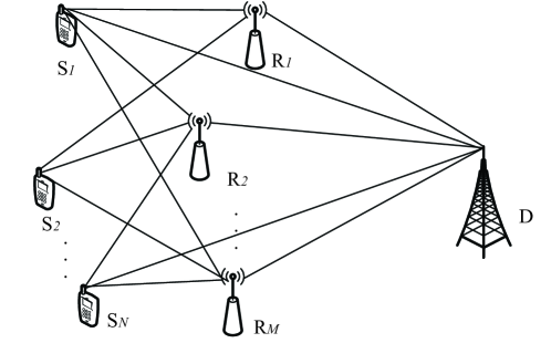
We consider an AF cooperative network with nodes, where users ( ) transmit individual information to one destination () with the aid of relays (). The system model is shown in Fig. 1. All the nodes are assumed to have single antenna and transmit with power , and operate in half-duplex mode. All the channels in the network are assumed to be independent flat Rayleigh block fading channels with additive white Gaussian noise (AWGN). We further assume that the variances of the channel coefficients of the , , and links are , , and , respectively, while the average noise power of each link in the network is .
II-B The Proposed US-LCRP
In [11] and [12], the relays serve one data block immediately after the data block’s direct transmission has been finished. In this TRA, the relays are dedicated to assist one data block in each relay time slot and brings no benefits for the other data blocks. Differently, we exploit the TRA as in [14, 15, 16, 17] where all the relays are shared by all the sources. To achieve this effect, the relays do not participate in assisting the signal transmission until all the direct transmissions have been finished. Therefore, the whole transmission is divided into two phases: the broadcast phase and the relay phase. First, the sources transmit data blocks in the broadcast phase. Afterwards, the relays assist the transmissions in the relay phase. Studies show that with the aid of a well-designed protocol, it is attractive to achieve the effect of “relay sharing”, which means that multiple sources are able to benefit from a single relay TS. The design objective of US-LCRP is to achieve both CD and MUD under the TP-TRA framework.
Different from [11, 12], in the proposed US-LCRP, we exploit the TRA framework as in [14, 15, 16, 17]. The whole transmission is divided into two phases: the broadcast phase and the relay phase. First, the sources transmit data blocks in the broadcast phase. Afterwards, the relays assist in transmissions in the broadcast phase. Studies show that with the aid of a well-designed protocol, it is attractive to achieve the effect of “relay sharing” which means that multiple sources are able to benefit from a single relay TS. The design objective of US-LCRP is to achieve both CD and MUD under the TP-TRA framework.
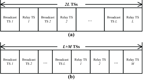
We assume that the broadcast phase occupies TSs. In each TS of the broadcast phase, the “best” user whose link towards the destination exhibits the highest SNR is selected as a candidate for transmission. Then in the relay phase, the relays assist in transmissions one by one, thus the relay phase lasts for TSs. In each relay TS, a single relay aids the transmission of the “worst” data block which has the lowest quality record at . Fig. 2(a) illustrates TP-TRA, and its details are presented as follows.
II-B1 Broadcast Phase
In the broadcast phase, a greedy scheduler is employed to obtain MUD. In the th broadcast TS, the scheduler chooses the “best” user whose link towards the destination has the highest SNR. Then, can be expressed as
| (1) |
where “BP” is the abbreviation of “broadcast phase”, represents the instantaneous SNR of the link in the th broadcast TS, and denotes the channel coefficient of this link in the th broadcast TS.
Due to the broadcast nature of wireless environment, all the relays and the destination can receive ’s signal. The received signal at and are
respectively, where is the channel coefficient of the link in the th broadcast TS, is the transmitted data block of in the th broadcast TS, and are the AWGN at and , respectively.
II-B2 Relay Phase
The relay phase lasts for TSs, during which all the relays participate in the transmission one by one, i.e., in a round-robin fashion. In the first relay TS, transmits, and then in the second relay TS, transmits. This procedure goes on until all the relays have assisted the transmission. In addition, the US-LCRP employs data block selection to facilitate the transmission. Briefly speaking, a single relay assists the transmission of the “worst” data block in each relay TS. After relays’ transmission, the destination performs data combining and then updates the quality record of the selected data block in order to prepare for the next relay TS. Since selective combining (SC) is capable of providing diversity order with rather low complexity, we focus on SC in this paper. It should be noted that other combining schemes such as maximum ratio combining (MRC) [18] and equal gain combining (EGC) can be readily introduced into the US-LCRP in the same way. The details of relay phase operation are described as follows.
We denote as the SNR of the received signals at related to after combining and before the th relay TS (i.e., the SNR of the combined signals from all the links over which has been transmitted to before the th relay TS), as the set of , where . Suppose , , and are the channel fading coefficients of the links and in the th relay TS, respectively, where “RP” is the abbreviation of “relay phase”. For the ease of exposition, the details of the calculation and the updating of will be explained later.
In the th relay TS, first selects the “worst” data block and broadcasts its index ,111This limited feedback information may be represented with bits. where
| (2) |
Then amplifies its observation of the data block and forwards it to . The destination receives the relayed signal, which is written as
| (3) |
where is the AWGN with zero mean and variance , is the version of amplified signal at and is expressed as
| (4) |
After finishes the transmission, employs SC to perform data combining. Finally, updates to and reconstructs a new SNR set to record all the data blocks’ quality of the next relay TS, and the current th TSs ends.
The relay phase continues until all the relays finish assisting the transmission and thereby lasts for TSs.
Below we will elaborate on the calculation and updating of . Note that the initial value of , namely , is equal to the SNR of the received signals at from after the broadcast phase, and it is computed as
| (5) |
In the th relay TS, relying on (4), the SNR of the received signal at (i.e., the SNR of ) is formulated as
| (6) | ||||
| (7) |
where is the SNR of the link in the th broadcast TS and can be expressed as , while is the SNR of the link in the th relay TS and can be expressed as
After data combining, is updated to . Additionally, denotes the SNR of the combined signal at the output of the selection combiner, thus it is written as
| (8) |
Since only the signal of the selected data block is relayed, the unselected data blocks’ quality records remain unchanged. Thus the elements of the updated SNR set are given by
| (9) |
II-B3 Discussions
Let us compare the proposed US-LCRP and the existing protocols in [11, 12]. The US-LCRP enjoys a lower implementation complexity. In [11], the CSI of all the links in the entire network has to be estimated for selecting the optimal “user-relay” pair selection. In [12], the CSI of only the direct links and of the relaying links has to be estimated for selecting the “proper” user and the “proper” relay. In contrast, the US-LCRP requires to estimate the CSI of only the direct links in the broadcast phase while in the relay phase it does not need to estimate any CSI. In each relay TS of the US-LCRP, the destination only has to evaluate the received SNR and update the users’ quality records. It should be noted that in each relay TS of the scheme proposed in [12], also has to estimate the received SNR of the relayed signal as in the proposed US-LCRP scheme, because it also has to combine the original signal and the relayed signal. Besides, only the quality of the selected “data block” is changed and updated in each relay TS of the proposed US-LCRP scheme, and the updating can be directly accomplished after the data combining, as shown in (9). As a result, the calculation and updating of each data block’s quality do not incur other overhead when compared with the scheme of [12].
Moreover, Fig. 2 illustrates the TRA of the US-LCRP and its counterparts in [11, 12]. We can observe from Fig. 2 that the US-LCRP occupies TSs whereas both schemes of [11] and [12] occupy TSs. It implies that if is set a larger value than , the US-LCRP has the potential to achieve higher spectral efficiency than the schemes of [11, 12], because the US-LCRP requires less time resources. This conclusion will be demonstrated by both the analytical results of Section III and the simulation results of Section IV, as detailed subsequently.
Let us now discuss the issue of feedback latency. In each TS of the proposed US-LCRP, the destination (i.e. BS) has to notify the selected users/relays with a limited amount of feedback information. It should be pointed out that such kind of feedback technique is widely exploited in wireless communications, and related works include, for example, the benchmark schemes of [11] and [12] considered in this paper. In the scheme of [11], the destination performs joint “user-relay” pair selection among all the candidates of the “user-relay” pairs. Therefore, the destination has to broadcast bits of feedback information to reveal the selection result, where denotes the ceiling operation. In the scheme of [12], the destination performs “optimal” user selection among all the candidates of users and “optimal” relay selection among all the candidates of relays in each broadcast time slot and each relay time slot, respectively. and bits feedback information is thus used for notifying the selected users and the selected relays, respectively. By contrast, in the proposed US-LCRP requires smaller amount of feedback information compared with its counterpart schemes in [11] and [12], when . Furthermore, feeding back a small amount of information is not difficult in practical systems such as LTE, where the feedback information is transmitted with much lower data rate and protected with much stronger channel codes to ensure a much lower error rate compared with the data since it is important and of small size. As a result, the feedback information could be regarded as approximately perfect. What’s more important, the latency brought by feedback is typically acceptable to satisfy the QoS requirement in current wireless communication systems. For instance, in LTE the ACK/NACK is sent four subframes later than the data block’s transmission, and the retransmission will happen four subframes later after the NACK is sent. In current wireless systems, the time granularity of scheduling is tiny enough and typically this latency does not affect user experience. In addition, in this way the resources could be used efficiently. The uplink and downlink usually use different frequency bands, and after the uplink/downlink feedback information has been sent, the base station/user equipment can use the downlink/uplink channel to transmit other information to the user equipment/base station.
III DMT Analysis
Both the reliability performance and the spectral efficiency are considered to verify the superiority of the US-LCRP. As is well known, the fundamental and comprehensive performance metric to simultaneously characterize the reliability and capacity performance is DMT [19]. DMT depicts the reliability with diversity gain and the capacity with multiplexing gain. It shows the achievable diversity gain of a given protocol under a certain multiplexing gain. In this section, the DMT performance of the US-LCRP is analyzed. For convenience of exposition, let us start with the definitions that will be used in our analysis.
III-A Definitions
We define as the set of SNRs of the received signals at in the broadcast phase and the relay phase. Considering (5), (7) and (8), we have , thus is defined as
| (10) |
We assume the elements of the set are ordered as .
Define , where represents the SNR of the combined signals of at after the whole transmission. Apparently,
| (11) |
We also assume the elements of the set are ordered as .
The average transmitted SNR of the network is defined as the effective signal to noise power ratio, namely
| (12) |
where is the transmission power at each node.
A system outage event occurs when does not correctly decode all the blocks after the whole transmission. Let us define as the maximum average mutual information between and the corresponding received signal at . For a given end-to-end data rate of , suffers an outage if . Thus the system outage takes place if the condition is not satisfied.
The multiplexing gain is defined as [19]
| (13) |
where is the end-to-end transmission data rate characterized as a function of the average SNR .
III-B DMT performance
Next, we proceed to analyze the DMT performance of our US-LCRP with the above definitions. Obviously, we need to evaluate the system outage probability with regard to the average SNR and the required end-to-end data rate. Relying on the definition of the system outage event, the system outage probability is expressed as
| (15) |
where is the cumulative distribution function (CDF) of , .
To begin with, let us study the equivalent SNR of the combined signal received at for each data block after the whole transmission is finished. In total there are data blocks transmitted during the whole transmission. Since one data block is discarded while making data combining in each relay TS, data blocks are retained for the final decision. First, we prove that the retained data blocks have better quality than the discarded data blocks. This conclusion is summarized in the following Lemma 1.
Lemma 1.
The SNRs of the retained data blocks are higher than that of the discarded data blocks, i.e.,
| (16) |
where is the th smallest SNR of the retained data blocks and is the th smallest SNR of all the data blocks as defined in Section III-A previously.
Proof:
Please see Appendix A. ∎
To calculate (18), we try to obtain the expression of . For , represents the CDF of the SNR of the strongest direct link in a single broadcast TS. Thus it is expressed as
| (19) | ||||
| (20) |
where . For , is the CDF of the SNR of the relayed signal in the th relay TS. However, in general networks where the distributions of the SNRs of all the links are characterized by different parameters, and hence the distribution of is varying corresponding to the specific values of . As a result, is written as
| (21) |
where
| (22) |
with , being , , respectively, and being the first order modified Bessel function of the second kind.
With the expression of the system outage probability, we can derive the DMT of the proposed US-LCRP.
Theorem 1.
In an -user -relay network with multiplexing gain , the proposed US-LCRP protocol with broadcast phase TSs achieves the DMT of
| (23) |
where represents .
Proof:
Please see Appendix B. ∎
III-C Discussions
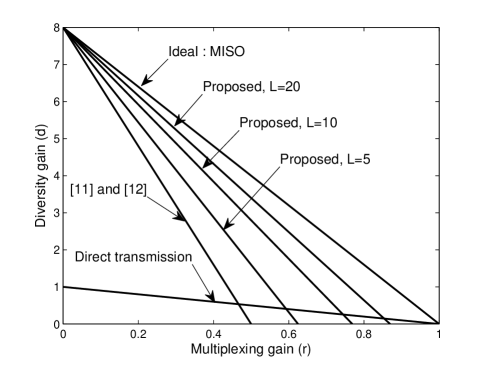
It is not difficult to prove that the existing protocols combining CD and MUD [11, 12] achieve the DMT of . Clearly, the proposed US-LCRP provides a diversity order of , similar to the existing protocols. However, in the network where , the US-LCRP achieves better DMT performance. In other words, the US-LCRP achieves higher spectral efficiency than the existing protocols while maintaining the same level of reliability, or it provides higher diversity gain than the existing protocols with the same data rate. Moreover, as is well known, the ideal DMT of an -input one-output network (an instance of the multiple-input single-output (MISO) network) is . However, it is practically infeasible to achieve such an ideal DMT in a cooperative network due to the potential excessively high complexity. It is demonstrated that as increases, the DMT of our US-LCRP approaches the ideal case.222(23) implies that as the value of goes to infinity, the achievable DMT performance of the US-LCRP approaches that of the ideal MISO scenario. In practical communication systems, the required buffer size in each relay linearly grows upon increasing the value of , because each relay has to store all the data blocks. Therefore, the value of should be set as large as possible subject to the limitation of the buffer size of the relays. As an example, we illustrate the DMT curves for various communication strategies in a five-source three-relay network in Fig. 3. When the multiplexing gain is , the existing protocols combining CD and MUD [11, 12] achieve a diversity gain of , while the US-LCRP achieves a diversity gain of , for . It demonstrates that the US-LCRP achieves higher diversity gain than the existing protocols while providing the same data rate. Moreover, the existing protocols of [11, 12] achieve a diversity gain of with multiplexing gain , while our US-LCRP achieves a diversity gain of and with multiplexing gain for and , respectively. This result implies that the US-LCRP is capable of offering higher data rate (i.e., larger multiplexing gain) with higher reliability (i.e. larger diversity gain) if is set to be sufficiently large.
IV Simulation Results
In this section, simulation results are presented to demonstrate the performance of the proposed US-LCRP in terms of the average system outage probability with different values of multiplexing gain. These results corroborate the validity of the proposed protocol and consolidate our DMT analysis presented in Section III. Here represents the ratio of the average transmit power to the noise power of the network. The simulations are performed over Rayleigh block fading channels with AWGNs. The network is generated in a two-dimensional plane where is located at the coordinate of , and the other nodes are uniformly distributed in the first quadrant of the square as [12]. The path loss exponent is set to .
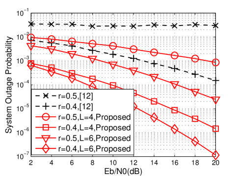
Fig. 4 shows the impact of and on the system outage performance of the proposed US-LCRP under fixed data rate . Observe that the US-LCRP achieves the diversity order of , equal to that of the existing low complexity scheme of [12]. Moreover, in terms of the system outage probability, the proposed protocol attains a considerable improvement in comparison with its counterpart in [12] in terms of the system outage probability. For example, this improvement is about when system outage probability is equal to in Fig. 4.
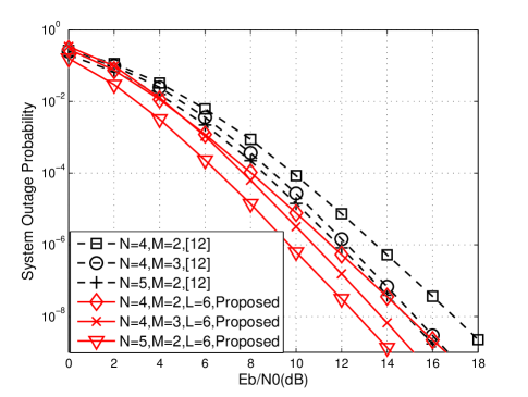
Fig. 5 shows the impact of data rate on the system outage performance of the existing low complexity scheme [12] and the proposed US-LCRP. We set in this simulation. The system outage probabilities of the proposed US-LCRP and of its counterpart [12] are illustrated in a five-user three-relay network under fixed data rate and , respectively. The upper bound and the lower bound are also illustrated, and the achievable simulation curves of reside between them. Thus our analysis of is consolidated. It is shown that when the system outage probability is equal to , the improvement of the proposed US-LCRP over the existing low complexity scheme of [12] is about and for and , respectively. We can also observe that the performance advantage of the proposed scheme over the scheme of [12] becomes more significant upon increasing . This is because the proposed scheme allocates more time resource to direct transmission (i.e., for the transmission of “fresh” data), and hence the required transmission rate of each link is reduced. More specifically, in order to achieve an end-to-end data rate of , the actual data rates of each link in the proposed scheme and in the scheme of [12] are and , respectively. Therefore, the gap of the required data rate in each link between the proposed scheme and the scheme of [12] grows as increases. As a beneficial result, it is demonstrated that the US-LCRP is more powerful in supporting high rate transmission than the scheme of [12].
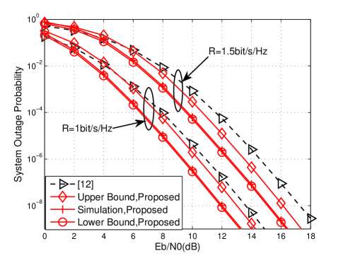
Fig. 6 illustrates the system outage probabilities of the proposed US-LCRP and the scheme of [12] under a range of different values of multiplexing gain. The desired data rate is determined by the multiplexing gain and the average SNR of the network as . It is observed that the US-LCRP achieves higher diversity gain than the scheme of [12]. For example, if we set , the diversity gains of the US-LCRP are and when and , respectively, whereas those of the existing scheme in [12] are and , respectively. Furthermore, Fig. 6 shows that the DMT of the US-LCRP becomes more attractive as increases. This result confirms that the proposed scheme has the potential to achieve better DMT performance than the scheme of [12]. It also implies that the proposed US-LCRP is the asymptotically optimal in the sense that the DMT of the US-LCRP becomes arbitrarily close to that of the ideal MISO scenario when is sufficiently large.
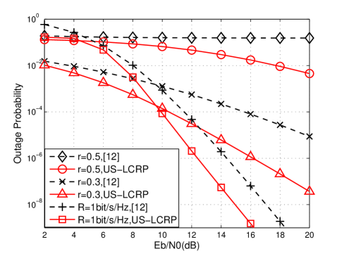
Simulation results for the network configured with other parameters are also presented. For example, in some systems, the relays are almost in the middle between the source and the destination to assist in the user’s transmission. Hence we assume that the sources are clustered around and the relays are clustered around , whereas the destination remains staying at . Additionally, larger path loss exponent, for instance , is considered. The comparison between the proposed US-LCRP and the scheme of [12] is depicted in Fig. 7. From Fig. 7 we can see that with fixed data rate, i.e. r=0, the scheme in [12] and US-LCRP both achieve the same diversity gain of 8. However, as the multiplexing gain increases, the diversity gain of the scheme in [12] decays much faster than the proposed US-LCRP. Based on the theoretical analysis, the US-LCRP achieves the diversity gain of and when and , respectively, whereas the scheme in [12] achieves diversity gain of and , respectively. These results are validated in Fig. 7.
V Conclusions
This paper addresses the problem of joint exploitation of both CD and MUD under the TP-TRA framework, in which the whole transmission is composed of the broadcast phase and the relay phase. Based on the TP-TRA framework, a user-selection based low complexity relay protocol (US-LCRP) is proposed to achieve both CD and MUD. The DMT performance of the proposed US-LCRP is analyzed, and simulations are carried out to corroborate the analysis. Both the theoretical analysis and simulation results demonstrate that the proposed US-LCRP combines CD and MUD successfully and achieves a total diversity order of in an -user -relay network. Furthermore, it provides better DMT performance and has the potential to approach the optimal DMT when certain mild conditions are satisfied. Finally, the proposed US-LCRP needs the CSI of only the direct links in each broadcast TS during the whole transmission, which results in a simpler implementation.
Appendix A Proof of Lemma 1
Obviously, all the elements in , which is defined in Section III-A, are mutually independent random variables (RVs). According to (9) and the definitions in Section III-A, we readily have for all and ( and ), and . From (2) and (9), we have if . It means that whenever is not selected in one relay TS, we can find an element that is less than . Similarly, we obtain if . It means that once is selected in the relay phase, an element is found333We have because both and are the elements of . to be less than . In summary, after each relay TS, we can always find an element in which is less than . Therefore, after the whole relay phase, there are at least elements in which are less than , i.e., . On the other hand, note that , then we have . Therefore, we obtain the result of , which indicates that is the th smallest SNR of all the received signals during the whole transmission.
Appendix B Proof of Theorem 1
It is very difficult to obtain the exact numerical results of (21) for general networks due to the complicated mathematical structure. However, in a special network where remains unchanged with different (i.e., can be expressed by a constant for all the ) , the expression of can be derived straightforwardly because . Therefore, can be obtained as
| (24) |
We refer to this special network as the symmetric network. In this appendix, we show that the DMTs of the two special symmetric networks serve as the upper bound and the lower bound of that of the original network, respectively, and the upper bound coincides with the lower bound. Therefore, we obtain the DMT of the US-LCRP in general cases.
Note that deriving DMT entails the analysis of the asymptotic performance. Specifically, we can construct some symmetric networks to facilitate the DMT analysis of the original asymmetric network. For any given general network, we establish two special -node symmetric networks. We assume that the SNRs of the , and links in the first symmetric network obey the exponential distributions with parameters , and , respectively, and the SNRs of the , and links in the second symmetric network obey the exponential distributions with parameters , and , respectively. In the first symmetric network, we set , and . Obviously, since the quality of each link in the first symmetric network is not better than that of the corresponding link in the original network, it suffers a higher system outage probability . Thus the upper bound of the original network’s outage probability is obtained by calculating the system outage probability of this special symmetric network using (24). Similarly, we can generate the second symmetric network where the source-to-relay links are guaranteed to have higher/equal qualities than/to the corresponding links in the original network, namely we have , and . As a result, we can obtain the lower bound of the original network’s outage probability by calculating the system outage probability of the second symmetric network. The mathematical derivation is represented below.
From [19], the diversity gain is computed as
Since is the upper bound of , we have
| (25) |
Acknowledgment
The authors would like to thank Walaa Hamouda and the anonymous reviewers for their valuable comments.
References
- [1] J. Proakis and M. Salehi, Digital communications, Fifth Edition, McGraw-Hill, New York, 2007.
- [2] J. Laneman, D. Tse, and G. Wornell, “Cooperative diversity in wireless networks: Efficient protocols and outage behavior,” IEEE Transactions on Information theory, vol. 50, no. 12, pp. 3062–3080, Dec. 2004.
- [3] Y. Jing, and H. Jafarkhani, “Single and multiple relay selection schemes and their achievable diversity orders,” IEEE Transactions on Wireless Communications, vol. 8, no. 3, pp. 1414–1423, Mar. 2009.
- [4] Y. Zhao, R. Adve, and T. Lim, “Symbol error rate of selection amplify-and-forward relay systems,” IEEE Communications Letters, vol. 10, no. 11, pp. 757–759, Nov. 2006.
- [5] A. Bletsas, H. Shin, and M. Win, “Cooperative communications with outage-optimal opportunistic relaying,” IEEE Transactions on Wireless Communications , vol. 6, no. 9, pp. 3450–3460, Sept. 2007.
- [6] D. Tse, “Multiuser diversity in wireless networks,” in Wireless Communications Seminar, Stanford University, 2001.
- [7] H. Joung, and C. Mun, “Capacity of multiuser diversity with cooperative relaying in wireless networks,” IEEE Communications Letters, vol. 12, no. 10, pp. 752–754, Oct. 2008.
- [8] Y. Jang, and W. Shin, and Y. Lee, “Multiuser scheduling based on reduced feedback information in cooperative communications,” in Proc. IEEE VTC-Spring 2009, Barcelona, Spain, Apr. 2009, pp. 1341–1345.
- [9] X. Zhang, S. Chen, and W. Wang, “Multiuser diversity in multiuser two-hop cooperative relay wireless networks: System model and performance analysis,” IEEE Transactions on Vehicular Technology, vol. 58, no. 2, pp. 1031–1036, Jul. 2009.
- [10] S. Chen, W. Wang, and X. Zhang, “Performance analysis of multiuser diversity in cooperative multi-relay networks under rayleigh-fading channels,” IEEE Transactions on Wireless Communications, vol. 8, no. 7, pp. 3415–3419, Jul. 2009.
- [11] L. Sun, T. Zhang, L. Lu, and H. Niu, “On the combination of cooperative diversity and multiuser diversity in multi-source multi-relay wireless networks,” IEEE Signal Processing Letters, vol. 17, no. 6, pp. 535–538, Jun. 2010.
- [12] H. Ding, J. Ge, D. Benevides da Costa, and Z. Jiang, “A new efficient low-complexity scheme for multi-source multi-relay cooperative networks,” IEEE Transactions on Vehicular Technology, vol. 60, no. 2, pp. 716–722, Feb. 2011.
- [13] A. Wiesel, J. Goldberg, and H. Messer-Yaron, “SNR estimation in time-varying fading channels,” IEEE Transactions on Communications, vol. 54, no. 5, pp. 841–848, May 2006.
- [14] C. Peng, Q. Zhang, M. Zhao, and Y. Yao, “On the performance analysis of network-coded cooperation in wireless networks,” in Proc. IEEE International Conference on Computer Communnications (INFOCOM), Alaska, USA, pp. 1460–1468, May 2007.
- [15] M. Xiao, and M. Skoglund, “Multiple-user cooperative communications based on linear network coding,” IEEE Transactions on Communications, vol. 58, no. 12, pp. 3345–3351, Dec. 2010.
- [16] J. Li, J. Yuan, R. Malancy, M. Xiao, and W. Chen, “Full-diversity binary frame-wise network coding for multiple-source multiple-relay networks over slow-fading channels,” IEEE Transactions on Vehicular Technology, vol. 61, no. 3, pp. 1346–1360, Mar. 2012.
- [17] Z. Zhang, T. Lv, and S. Yang, “Round-robin relaying with diversity in amplify-and-forward multi-source cooperative communications,” IEEE Transactions on Vehicular Technology, vol. 62, no. 3, pp. 1251-1266, Mar. 2013.
- [18] D. Chase, “Code combining-a maximum-likelihood decoding approach for combining an arbitrary number of noisy packets,” IEEE Transactions on Communications, vol. 33, no. 5, pp. 385–393, May 1985.
- [19] L. Zheng, and D. Tse, “Diversity and multiplexing: a fundamental tradeoff in multiple-antenna channels,” IEEE Transactions on Information Theory, vol. 49, no. 5, pp. 1073–1096, May 2003.
- [20] H. Min, S. Lee, K. Kwak, and D. Hong, “Effect of multiple antennas at the source on outage probability for amplify-and-forward relaying systems,” IEEE Transactions on Wireless Communications, vol. 8, no. 2, pp. 633–637, Feb. 2009.
- [21] M. Safari, and M. Uysal, “Cooperative diversity over log-normal fading channels: performance analysis and optimization,” IEEE Transactions on Wireless Communications, vol. 7, no. 5, pp. 1963–1972, May 2008.
- [22] S. Ikki, and M. Ahmed, “Exact Error Probability and Channel Capacity of the Best-Relay Cooperative-Diversity Networks,” IEEE Signal Processing Letters, vol. 16, no. 12, pp. 1051–1054, May 2009.
- [23] F. Xu , F. C. M. Lau, Q. F. Zhou, and D. W. Yue, “Outage performance of cooperative communication systems using opportunistic relaying and selection combining receiver,” IEEE Signal Processing Letters, vol. 16, no. 4, pp. 237–240, May 2009.
- [24] T. Chang, W. Ma, C. Huang, and C. Chi, “Noncoherent OSTBC-OFDM for MIMO and Cooperative Communications: Perfect Channel Identifiability and Achievable Diversity Order,” IEEE Transactions on Signal Processing, vol. 60, no. 9, pp. 4849–4863, Sep. 2012.
- [25] Q. Liu, X. Ma, and G. Zhou, “A General Diversity Gain Function and Its Application in Amplify-and-Forward Cooperative Networks,” IEEE Transactions on Signal Processing, vol. 59, no. 2, pp. 859–863, Feb. 2011.
![[Uncaptioned image]](/html/1310.3248/assets/x8.png) |
Tiejun Lv (M’08-SM’12) received the M.S. and Ph.D. degrees in electronic engineering from the University of Electronic Science and Technology of China (UESTC), Chengdu, China, in 1997 and 2000, respectively. From January 2001 to December 2002, he was a Postdoctoral Fellow with Tsinghua University, Beijing, China. From September 2008 to March 2009, he was a Visiting Professor with the Department of Electrical Engineering, Stanford University, Stanford, CA. He is currently a Full Professor with the School of Information and Communication Engineering, Beijing University of Posts and Telecommunications (BUPT). He is the author of more than 100 published technical papers on the physical layer of wireless mobile communications. His current research interests include signal processing, communications theory and networking. Dr. Lv is also a Senior Member of the Chinese Electronics Association. He was the recipient of the Program for New Century Excellent Talents in University Award from the Ministry of Education, China, in 2006. |
![[Uncaptioned image]](/html/1310.3248/assets/x9.png) |
Zhang Zhang received the B.Eng. and Ph.D. degrees from Beijing University of Posts and Telecommunications (BUPT), Beijing, China, in 2007 and 2012, respectively. From May 2009 to June 2012, he also served as a Research Assistant for the Wireless and Mobile Communications Technology RD Center, Tsinghua University, Beijing, China. He is currently with the Department of Research and Innovation, Alcatel Lucent Shanghai Bell, Shanghai, China. His current research interests include cooperative communication, network coding, machine type communication and network information theory. |
![[Uncaptioned image]](/html/1310.3248/assets/x10.png) |
Shaoshi Yang (S’09-M’13) (https://sites.google.com/site/shaoshiyang/) received the B.Eng. Degree in information engineering from Beijing University of Posts and Telecommunications, China, in 2006, and Ph.D. Degree in wireless communications from University of Southampton, U.K., in 2013. He is now working as a Postdoctoral Research Fellow in University of Southampton, U.K. From November 2008 to February 2009, he was an Intern Research Fellow with the Communications Technology Laboratory, Intel Labs China, Beijing, where he focused on Channel Quality Indicator Channel design for mobile WiMAX (802.16 m). His research interests include multiple-input–mutliple-output (MIMO) signal processing, multicell joint/distributed signal processing, cooperative communications, green radio, and interference management. He has published in excess of 25 research papers on IEEE journals and conferences. Shaoshi is a recipient of the PMC-Sierra Telecommunications Technology Scholarship, and a Junior Member of the Isaac Newton Institute for Mathematical Sciences, Cambridge, UK. He is also a TPC member of the 23rd Annual IEEE International Symposium on Personal, Indoor and Mobile Radio Communications (IEEE PIMRC 2012), of the 48th Annual IEEE International Conference on Communications (IEEE ICC 2013), and of the 2nd IEEE/SAE/ACM/IFAC International Conference on Connected Vehicles and Expo (ICCVE 2013). |