A programmable quantum current standard from the Josephson and the quantum Hall effects
Abstract
We propose a way to realize a programmable quantum current standard (PQCS) from the Josephson voltage standard and the quantum Hall resistance standard (QHR) exploiting the multiple connection technique provided by the quantum Hall effect (QHE) and the exactness of the cryogenic current comparator. The PQCS could lead to breakthroughs in electrical metrology like the realization of a programmable quantum current source, a quantum ampere-meter and a simplified closure of the quantum metrological triangle. Moreover, very accurate universality tests of the QHE could be performed by comparing PQCS based on different QHRs.
pacs:
73.43.-f, 74.81.Fa, 73.23.Hk, 06.20.fb, 06.20.Jr, 84.37.+qI Introduction
The quantum Hall effect (QHE)v. Klitzing, Dorda, and Pepper (1980) and the Josephson effect (JE)Josepshon (1962); Shapiro (1963) provide universal and reproducible resistanceJeckelmann and Jeanneret (2001); Poirier and Schopfer (2009) and voltageJeanneret and Benz (2009) standards respectively linked to the electron charge e and the Planck constant h only. The QHE manifests itself by the Hall resistance quantization in a two-dimensional electron gas (2DEG) at values in the non-dissipative transport limit ( is an integer and is the von Klitzing constant equal to in theory). The reproducibility of the quantum Hall resistance was checkedJeckelmann and Jeanneret (2001); Janssen et al. (2011); Schopfer and Poirier (2013) with a relative uncertainty of a few . Thereby, the unit ohm can be currently maintained in national metrology institutes (NMIs) with a relative uncertainty of . The application of the QHE in metrology was more recently enlarged by its implementation in the alternating current (AC) regimeAhlers et al. (2009) and by the development of quantized Hall array resistance standards (QHARS)Poirier et al. (2002); Poirier and Schopfer (2009). These successes rely on a technique of multiple connection which cancels the effect of any impedance connected in series to the Hall bar terminalsDelahaye (1993). Progress in resistance metrology has also resulted from the advent of resistance bridges based on cryogenic current comparators (CCC)Harvey (1972). The CCC is a perfect transformer which can measure a current ratio in terms of the number of winding turns ratio with a relative uncertaintyPoirier and Schopfer (2009) as low as . Its accuracy relies on a flux density conservation property of the superconductive toroidal shield (Meissner effect) in which superconducting windings are embedded. Owing to a flux detector based on a superconducting quantum interference device (SQUID), a CCC can have a current sensitivity as low as 1 fA/ at frequencies down to 1 Hz. The JE provides a quantized reference voltageJeanneret and Benz (2009) where is an integer, is the frequency of an electromagnetic radiation and the Josephson constant, theoretically equal to . The universal character of was testedTsai and al (1983); Jain, Lukens, and Tsai (1987) with an uncertainty of a few . Owing to the development of arrays composed of a large number of underdamped Josephson junctions (JJ) generating a quantized voltage as large as 10 V, the JE is currently used in NMIs to maintain the unit volt with an accuracy of a few . Programmable Josephson array voltage standards (PJAVS) were more recently developed to generate arbitrary voltage waveforms. They are based on arrays of overdamped JJKohlmann and Behr (2011) (up to 70000) divided into segments containing numbers of JJ following a binary sequence and which are independently biased by a digitally programmable current source.
Despite the unit ampere is one of the seven base units of the Système International (SI)BIPM , its old definitionCom cannot be implemented with the accuracy required for calibration needs. Moreover, the current unit cannot be maintained using current generators mainly because of their lack of stability and of a certain sensitivity on the load of the device under test. Nowadays, the current is rather calibrated by applying the Ohm’s law to a voltage and a resistance independently calibrated in terms of and respectively. The relative uncertainty proposed by NMIs for current in the range from A up to A is not less than about . A true current standard accurate within a few is thus missing.
To overcome this lack, a lot of research efforts have been spent to develop a quantum current standard over the last two decadesFeltin and Piquemal (2009). The most advanced idea is based on handling of single charge carriers one by one in mesoscopic system where the charge quantization manifests itself due to Coulomb blockadeGrabert and Devoret (1992). Hence single-electron pumpsPothier et al. (1992) deliver a quantized current given by where , and are the number of charges per cycle, the elementary charge and the driven frequency respectively. Several kinds of single-electron pumps were proposed as reviewed in referencePekola et al. (2013); Scherer and Camarota (2012). In a seven junctions metallic pump, the reproducibility of the charge transfer has been demonstratedKeller et al. (1996) by measuring an error rate per cycle as low as . An interesting and stringent test of the accuracy of these single-electron pumps relies on a calibration of the quantized current in terms of and , also referred to as the closure of the quantum metrological triangle (QMT)Likharev and Zorin (1985). This experiment allows the measurement of the product which is expected to be equal to 2. Any deviation from this value would question the expected theoretical values , and of the constants , and respectivelyPiquemal and Genevès (2000). At the time of writing, the relative uncertainty of this determinationPekola et al. (2013); Scherer and Camarota (2012) is limited to about . Reducing this uncertainty to a few is an issue to demonstrate the consistency of the solid state theory with an accuracy allowing an evolution towards a SI based on fixed fundamental constantsBIPM . Let us remark that closing the metrological triangle also leads to an estimate value of the elementary charge from the determinations of and .
In this paper, we propose a way to realize a programmable quantum current standard (PQCS) from a special series arrangement of the Josephson voltage standard (JVS) and the quantum Hall resistance standard (QHR) with the CCC. We then discuss how this PQCS can lead to a breakthrough in some key metrological experiments and in particular in the closure of the QMT.
II Principle of the programmable quantum current standard
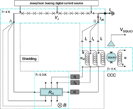
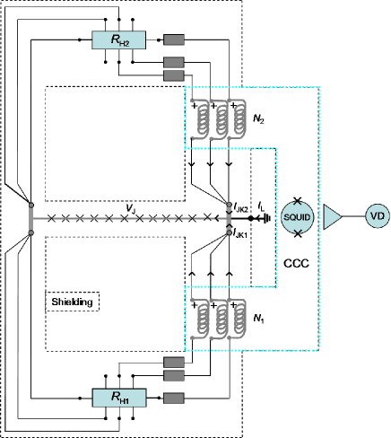
The principle of the PQCS consists in realizing the current where is the voltage generated by a PJAVS biased on a quantized voltage step and is the resistance of a quantum Hall resistance standard (QHR). The PQCS is theoretically quantized at current values . The main concern of the metrologist is to generate this current and then to use it as a reference for applications without degrading its quantum accuracy. The implementation is described in fig. 1. The PJAVS maintains the voltage between the nodes A and B. The QHR of resistance is connected at these nodes using a triple series connection (a similar connection scheme is used in AC regimeDelahaye (1995); Ahlers et al. (2009)) with the peculiarity that a CCC winding of number of turns is inserted in each of the three wires connecting the node B to the terminals of the Hall bar. A CCC auxiliary winding of turns is connected to different external circuits. Thus, the CCC allows the use of the quantized current as a reference in different metrological applications as explained in the following. Because nodes A and B which are the pads on the Josephson array chip are superconducting, the total current supplied by the PJAVS does not generate additional voltage drop at the nodes where the QHR is connected. Moreover, the triple series connection drastically reduces the discrepancy, caused by contact resistances, of the two-terminal resistance defined between A and B points to the quantized resistance . We therefore expect accurately close to .
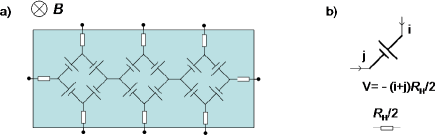
More precisely, let us note , and the three currents circulating in the wires from node B to the terminals of the QHR and , and the resistances of the connections expressed in relative value of (resistances of wires, windings and Hall bar terminal contacts). To simplify the discussion, only the resistances of the links connecting the QHR terminals (located on one equipotential edge) to the ground are considered. The currents , and and the resistance can be calculated using a Ricketts and Kemeny electrical model of the Hall barRicketts and Kemeny (1988) where the longitudinal resistivity is neglected (see fig. 2):
It results that the main current differs from () by only a third order correction in :
| (1) |
The ampere-turns injected in the CCC is where is close to within a third order correction in . If , the current and the ampere-turns depart from their quantized values () and by less than in relative value. Thus, the proposed new connection scheme allows the exact injection of ampere-turns generated by the programmable quantized current in the CCC.
Several conditions have to be fulfilled to ensure that this ideal description holds in an experiment. Electromotive forces (emfs) generated along wires between helium temperature and room temperature should be compensated by an efficient offset substraction procedure. Increasing both the Josephson voltage and the resistance of the QHR and keeping constant their ratio reduces the impact of emfs. The QHR can be either a single Hall bar or a QHARS provided that the current supplied in the circuit is lower that the current width of the Josephson voltage steps which amounts to some mA in modern PJAVS. For a Josephson voltage of 1 V and a QHR of resistance (a single Hall bar operating on the plateau where is the Landau level filling factor) the current is about . Moreover, leakage currents responsible for a difference between the total currents circulating through the QHR and the CCC should be cancelled. These leakage currents can be strongly reduced by connecting to ground both the low potential of the Josephson array and the shielding of each wire of the setup. By this way, any leakage current is redirected to ground. The direct leakage current short-circuiting the QHR, the most troublesome, is thus cancelled. However, the potential at the current terminal of the QHR (potentials at the voltage terminals of the QHR are very close to ground potential) leads to the circulation of a residual small leakage current towards ground that short-circuits the first CCC winding, where is the insulating resistance to ground of the cable. This results in the injection of an ampere-turns value in the CCC that departs from its nominal value by about in relative value. Assuming , (easily achieved using cables with polytetrafluoroetylene insulator) and leads to a relative discrepancy much smaller than . Now we will detail some metrological applications in which the quantized current can be used.
III Applications of the PQCS
III.1 Realization of a programmable quantum current source
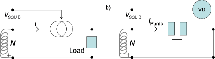
A programmable quantum current source can be realized by servo-controlling an external current source by the PQCS. This external current source which is connected in series with a winding of turns of the CCC is controlled by the feedback signal of the SQUID electronics to null the ampere-turns value in the CCC (see Fig. 3a). The Type BJCGM (2008) evaluation of the uncertainty component of the quantum current source essentially reduces to the negligible contribution of the winding turn ratio uncertainty since leakage current contribution of the PQCS is strongly cancelled. The noise spectral density (in A/) of the quantum current source caused by the Johnson-Nyquist noise of the quantum resistance standard and the SQUID noise is given by:
| (2) |
is the Boltzmann’s constant, is the gain of the CCC expressed in A.turns/ ( is the flux quantum) and is the SQUID noise spectral density in and is the temperature of the QHR. Let us consider the following values: , , , . Table 1 shows the excellent noise performance of the source and the expected Type AJCGM (2008) evaluation of the relative uncertainty component of the average value over 100 secondes in the current range from tens of pA to a few mA.
| 1 V | 1 | 100 | mA | ||
|---|---|---|---|---|---|
| 1 V | 1 | 1 | A | ||
| 1 V | 10000 | 1 | |||
| 10 mV | 10000 | 1 |
III.2 Realization of a programmable quantum ampere-meter to close the QMT
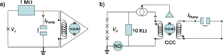
Another application is the realization of a quantum ampere-meter that can be used to close the QMT. One approach to realize this experiment, proposed by the Finnish NMI (Centre for Metrology and Accreditation)Manninen et al. (2008); Kemppinen et al. (2010), consists in comparing the single electron current pump with the current delivered by a single Josephson junction in series with a high value resistor (typically 1 M) by means of a SQUID-based current null detector to measure the unbalance current. On one hand, this mounting (see fig. 4a) offers the advantage of a current detection near equilibrium, but on the other hand it faces the difficult calibration of a high value resistor placed at low temperature. A similar experiment was realized by the NMI of United Kingdom (National Physical Laboratory) using a voltage source, a current detector and a resistor implemented at room temperature. The measurement accuracy of the current pump was limited to in relative value by the Johnson-Nyquist noise of the resistor and the calibration uncertainty of the room temperature apparatusGiblin et al. (2012). The French NMI (Laboratoire National de métrologie et d’Essais)Devoille et al. (2012) rather proposed to oppose the voltage of a Josephson array to the voltage drop at the terminals of a 10-k resistor fed by the current obtained after amplification by the CCC of the pump current (see fig. 4b). The calibration of the resistor is greatly simplified, but this simplification is done at the expense of a more complicated detection phase. Indeed, two different null detectors are needed: a zero flux detection in the SQUID loop and a zero voltage detection in the opposition circuit at room temperature. Moreover, the current amplification relies on a SQUID feedback control of the current source supplying the resistor in series with a CCC winding which is more delicate to operate and generally causes noise enhancement. More precisely, the frequency bandwidth of the external feedback is limited by the CCC internal resonance (at a few kHz) which makes the SQUID submitted to high-frequency flux noise. Due to the intrinsic nonlinearity of the SQUID response, this can lead to unwanted rectified signals altering the measurement accuracy.
We propose, as described in Fig. 3b, to oppose by means of the CCC the ampere-turns delivered by the PQCS described above to the ampere-turns generated by the single-electron pump where is the large number of turns of a CCC winding. At equilibrium, the product is simply determined from . In practice, , and can be adjusted so that the CCC detects zero ampere-turns value. The cancellation of the flux in the SQUID loop is ensured by an internal feedback. This implementation of the QMT is therefore strongly simplified since neither a voltage detector nor the implementation of an external feedback control of an amplified current source by the SQUID is required. It gathers the advantages of the two experiments described in fig. 4. The best measurement performance requires placing the single-electron current pump and the CCC in the same cryostat in order to avoid additional external noise. For , and the CCC characteristics considered previously, the PQCS has a contribution to the measurement noise (due to the Johnson-Nyquist noise of the QHR) one thousand lower than that of the SQUID. The relative uncertainty per of the determination of thus boils down to . One finds for a quantum standard nominal current of 100 pA. The target relative uncertainty of should therefore be reached for a reasonable acquisition time of about 150 hours.
III.3 Comparison of quantum Hall resistance standards
The last application consists in comparing the resistances of two QHRs ( and ) biased by a common Josephson voltage (see fig. 5). Using two sets of three windings (number of turns and ) of the CCC, the ampere-turns and generated by the quantized currents and are opposed. The resistance ratio is then determined from the measurement of the ampere-turns unbalance by the CCC. In principle, a Josephson quantized voltage is not necessary in this experiment. However, the superconducting pads of the JVS ensure that the voltages biasing the two PQCS circuits are exactly the same despite the circulation of currents. Moreover, the stability and the low noise of the JVS constitute advantages to achieve the lowest measurement uncertainty for the comparison of resistances. If made of different materials, for example of graphene and GaAs, this resistance comparison leads to the realization of a very accurate universality test of the QHE. This measurement technique based on the comparison of two PQCS is more accurate than the one based on the use of a usual cryogenic resistance bridge because the measurement is not poisoned by the nanovoltmeter noise and leakage currents are efficiently cancelled. The relative uncertainty of the determination of the resistance ratio is given by:
Considering , , and =0.3 K leads to . This comparison method is as accurate as the Wheatstone bridge techniqueSchopfer and Poirier (2013). Comparatively, it allows in addition the resistance comparison of quantum Hall resistors having different values. It should allow a strong improvement of the universality test of the QHE at different filling factors not only in the integer regime but also in the fractional regime.
IV Conclusion
To conclude, this paper describes a PQCS realized from the Josephson and the quantum Hall effects with an accuracy limited by the Johnson-Nyquist noise of the QHR and the SQUID noise only. We show how it can be used to realize a programmable quantum current source and a quantum ampere-meter, to improve the closure of the QMT and the accuracy of quantum resistor comparisons. Let us finally remark that the PQCS could be adapted to operate in the audio-frequency (a few kHz) AC regime. This requires the implementation of a coaxial circuitry, a PJAVS high-speed biasing current source and the replacement of the CCC by an accurate AC transformer.
Acknowledgements.
We wish to acknowledge O. Thévenot and P. Gournay as well as the staff of the LNE electrical calibration department for fruitful discussions.References
- v. Klitzing, Dorda, and Pepper (1980) K. v. Klitzing, G. Dorda, and M. Pepper, Phys. Rev. Lett. 45, 494 (1980).
- Josepshon (1962) B. D. Josepshon, Phys. Lett. 1, 251 (1962).
- Shapiro (1963) S. Shapiro, Phys. Rev. Lett. 11, 80 (1963).
- Jeckelmann and Jeanneret (2001) B. Jeckelmann and B. Jeanneret, Rep. Prog. Phys. 64, 1603 (2001).
- Poirier and Schopfer (2009) W. Poirier and F. Schopfer, Eur. Phys. J. Special Topics 172, 207 (2009).
- Jeanneret and Benz (2009) B. Jeanneret and S. P. Benz, Eur. Phys. J. Special Topics 172, 181 (2009).
- Janssen et al. (2011) T. J. B. M. Janssen, N. Fletcher, R. Goebel, J. Williams, A. Tzalenchuk, R. Yakimova, S. Kubatkin, S. Lara-Avila, and V. Fal ko, New J. Phys. 13, 093026 (2011).
- Schopfer and Poirier (2013) F. Schopfer and W. Poirier, J. Appl. Phys. 114, 064508 (2013).
- Ahlers et al. (2009) F. J. Ahlers, B. Jeannneret, F. Overney, J. Schurr, and B. M. Wood, Metrologia 46, R1 (2009).
- Poirier et al. (2002) W. Poirier, A. Bounouh, K. Hayashi, F. Piquemal, G. Genevès, and J. P. André, J. Appl. Phys. 92, 2002 (2002).
- Delahaye (1993) F. Delahaye, J. Appl. Phys. 73, 7914 (1993).
- Harvey (1972) I. K. Harvey, Rev. Sci. Instrum. 43, 1626 (1972).
- Tsai and al (1983) J. Tsai and al, Phys. Rev. Lett. 51, 316 (1983).
- Jain, Lukens, and Tsai (1987) A. K. Jain, J. E. Lukens, and J. S. Tsai, Phys. Rev. Lett. 58, 1165 (1987).
- Kohlmann and Behr (2011) J. Kohlmann and R. Behr, in Superconductivity - Theory and Applications, edited by D. A. Luiz (Intech, 2011) pp. 239–260.
- (16) BIPM, The International System of units (SI) (http://www.bipm.org/en/si/, Sèvres).
- (17) The ampere is that constant current which, if maintained in two straight parallel conductors of infinite length, of negligible circular cross-section, and placed 1 metre apart in vacuum, would produce between these conductors a force equal to newton per metre of length .
- Feltin and Piquemal (2009) N. Feltin and F. Piquemal, Eur. Phys. J. Special Topics 172, 267 (2009).
- Grabert and Devoret (1992) H. Grabert and M. H. Devoret, eds., Single charge tunneling Coulomb blockade phenomena in nanostructures, New York, NATO ASI Series, Series B: Physics 294 (Plenum Press, 1992).
- Pothier et al. (1992) H. Pothier, P. Lafarge, C. Urbina, D. Estève, and M. H. Devoret, Eur. Phys. Lett. 17, 249 (1992).
- Pekola et al. (2013) J. P. Pekola, O.-P. Saira, V. F. Maisi, A. Kemppinen, M. Mottonen, Y. A. Pashkin, and D. V. Averin, Rev. Mod. Phys. 85, 1421 (2013).
- Scherer and Camarota (2012) H. Scherer and B. Camarota, Meas. Sci. Technolo. 23, 124010 (2012).
- Keller et al. (1996) M. W. Keller, J. M. Martinis, N. M. Zimmermann, and A. H. Steinbach, Appl. Phys. Lett. 69, 1804 (1996).
- Likharev and Zorin (1985) K. K. Likharev and A. B. Zorin, J. Low Temp. Phys. 59, 347 (1985).
- Piquemal and Genevès (2000) F. Piquemal and G. Genevès, Metrologia 37, 207 (2000).
- Delahaye (1995) F. Delahaye, Metrologia 31, 367 (1995).
- Ricketts and Kemeny (1988) B. W. Ricketts and P. C. Kemeny, J. Phys. D 21, 483 (1988).
- JCGM (2008) JCGM, Evaluation of measurement data, Guide to the expression of uncertainty in measurement (http://www.bipm.org/fr/publications/guides/gum.html, 2008).
- Manninen et al. (2008) A. Manninen, O. Hahtela, P. Hakonen, J. Hassel, P. Helisto, A. Kemppinen, M. Mottonen, M. Paalanen, J. Pekola, A. Satrapinski, and H. Seppa, in 2008 CPEM Digest, Boulder, edited by A. H. Cookson and T.-L. Winter (IEEE Trans. Instrum., 2008) p. 630.
- Kemppinen et al. (2010) A. Kemppinen, S. Kafanov, V. F. Maisi, Y. A. Pashkin, S. V. Lotkhov, N. Chekurov, O.-P. Saira, M. Mottonen, J. Hassel, J. S. Tsai, D. V. Averin, A. B. Zorin, A. J. Manninen, and J. P. Pekola, in 2010 CPEM Digest, Daejeon, edited by Y. S. Song and J.-S. Kang (IEEE Trans. Instrum., 2010) p. 125.
- Giblin et al. (2012) S. P. Giblin, M. Kataoka, J. D. Fletcher, P. See, T. J. B. M. Janssen, J. P. Griffiths, G. A. C. Jones, I. Farrer, and D. A. Ritchie, Nat. Commun. 3, 930 (2012).
- Devoille et al. (2012) L. Devoille, N. Feltin, B. Steck, B. Chenaud, S. Sassine, S. Djordevic, O. Séron, and F. Piquemal, Meas. Sci. Technolo. 23, 124011 (2012).