ELECTRON CLOUD EFFECTS IN ACCELERATORS††thanks: Work supported by the US DOE under contract DE-AC02-05CH11231.
Abstract
We present a brief summary of various aspects of the electron-cloud effect (ECE) in accelerators.
For further details, the reader is encouraged to refer to the proceedings of many prior workshops, either dedicated to EC or with significant EC contents, including the entire “ECLOUD” series [1, 2, 3, 4, 5, 6, 7, 8, 9, 10, 11, 12, 13, 14, 15, 16, 18, 17, 19, 20, 21, 22]. In addition, the proceedings of the various flavors of Particle Accelerator Conferences [23] contain a large number of EC-related publications. The ICFA Beam Dynamics Newsletter series [24] contains one dedicated issue, and several occasional articles, on EC. An extensive reference database is the LHC website on EC [25].
1 Introduction
The qualitative picture of the development of an electron cloud for a bunched beam is as follows:
-
1.
Upon being injected into an empty chamber, a beam generates electrons by one or more mechanisms; these electrons are usually referred to as primary, or seed, electrons.
-
2.
These primary electrons get rattled around the chamber from the passage of successive bunches.
-
3.
As these electrons hit the chamber surface they yield secondary electrons, which are, in turn, added to the existing electron population.
This process repeats with the passage of successive bunches. An essential ingredient of the build-up and dissipation of the EC is the secondary electron yield (SEY) of the chamber surface, characterized by the function , where is the electron-wall impact energy. The function has a peak typically ranging in at an energy typically ranging in eV. A convenient phenomenological parameter is the effective SEY, , defined to be the average of over all electron-wall collisions during a relevant time window. Unfortunately, there is no simple a-priori way to determine , because it depends in a complicated way on a combination of many of the beam and chamber parameters.
If , the chamber wall acts as a net absorber of electrons and the EC density grows linearly in time following beam injection into an empty chamber. The growth saturates when the net number of electrons generated by primary mechanisms balances the net number of electrons absorbed by the walls.
If , the EC initially grows exponentially. This exponential growth slows down as the space-charge fields from the electrons effectively neutralize the beam field, reducing the electron acceleration. Ultimately, the process stops when the EC space-charge fields are strong enough to repel the electrons back to the walls of the chamber upon being born, at which point becomes . At this point, the EC distribution reaches a dynamical equilibrium characterized by rapid temporal and spatial fluctuations, determined by the bunch size and other variables. For typical present-day storage rings, whether using positron or proton beams, the average reaches a level m-3, the energy spectrum of the electrons typically peaks at an energy below eV, and has a high-energy tail reaching out to keV’s. In more detail, however, the EC distribution reaches a dynamical equilibrium characterized by temporal and spatial fluctuations. The temporal fluctuations span a typical range s, depending on the bunch length and intensity, and on the bunch train length and fill pattern. Spatial fluctuations typically span the range m, depending on the transverse bunch size and transverse dimensions of the vacuum chamber, and external magnetic field if any. The density gradually decays following beam extraction, or during the passage of a gap in the beam. The decay rate is controlled by the low- value (typically eV) of . In general, there is no simple, direct correlation between the rise time and the fall time of the buildup of [26]. Figure 1 illustrates the build-up of the electron cloud in the LHC.

The ECE combines many parameters of a storage ring such as bunch intensity, size and spacing, beam energy [27], vacuum chamber geometry, vacuum pressure, and electronic properties of the chamber surface material such as photon reflectivity , effective photoelectric yield (or quantum efficiency) , the SEY, the secondary emission spectrum [28, 29], etc.
In regions of the storage ring with an external magnetic field, such as dipole bending magnets, quadrupoles, etc., the EC distribution develops characteristic geometrical patterns. For typical magnetic fields in the range T and typical EC energies eV, the electrons move in tightly-wound spiral trajectories about the field lines. Thus in practice, in a bending dipole, the electrons are free to move in the vertical () direction, but are essentially frozen in the horizontal (). As a result, the -kick imparted by the beam on a given electron has an dependence that is remembered by the electron for many bunch passages. It often happens that the electron-wall impact energy equals at an -location less than the horizontal chamber radius. At this location , hence is maximum, leading to characteristic high-density vertical stripes symmetrically located about [30]. For quadrupole magnets, the EC distribution develops a characteristic four-fold pattern, with characteristic four-fold stripes [31].
In summary, the electron-cloud formation and dissipation:
-
•
Is characterized by rich physics, involving many ingredients pertaining to the beam and its environment.
-
•
Involves a broad range of energy and time scales.
-
•
Is always undesirable in particle accelerators.
-
•
Is often a performance-limiting problem, especially in present and future high-intensity storage rings.
-
•
Is challenging to accurately quantify, predict and extrapolate.
The electron cloud has been shown to be detrimental to the performance of many storage rings, and is a concern for future such machines, which typically call for high beam intensity and compact vacuum chambers. At any given storage ring, adverse effects may include one or more of the following: sudden, large, vacuum pressure rise; beam instabilities; emittance growth; interference with diagnostic instrumentation; excessive heat deposition on the chamber walls; etc. Mitigation mechanisms have been required in most cases in order to reach, or exceed, the design performance of the machine.
A more extensive summary of the ECE and its history is presented in Ref. [32].
2 Primary and secondary electrons
The main sources of primary electrons are: photoemission from synchrotron-radiated photons striking the chamber walls; ionization of residual gas; and electron generation from stray beam particles striking the walls of the chamber. Depending on the type of machine, one of these three processes is typically dominant. For example, in positron or electron storage rings, upon traversing the bending magnets, the beam usually emits copious synchrotron radiation with a keV critical energy, yielding photoelectrons upon striking the vacuum chamber. In proton rings, the process is typically initiated by ionization of residual gas, or from electron generation when stray beam particles strike the chamber. A notable exception is the LHC, which is the first proton storage ring ever built in which the beam emits significant synchrotron radiation, photons per proton per bending magnet traversal, with a photon critical energy eV [33]. In this case, photoemission is the dominant primary mechanism.
Primary emission mechanisms are usually insufficient to lead to a significant EC density. However, the average electron-wall impact energy is typically 100–200 eV, at which the SEY function is significant. If the effective SEY is , secondary emission readily exponentiates in time, which can lead to a large amplification factor, typically a few orders of magnitude, over the primary electron density, and to strong temporal and spatial fluctuations in the electron distribution [34]. This compounding effect of secondary emission is usually the main determinant of the strength of the ECEs, and is particularly strong in positively-charged bunched beams (in negatively-charged beams, the electrons born at the walls are pushed back towards the walls with relatively low energy, typically resulting in relatively inefficient secondary emission).
Photoemission and secondary electron emission depend differently on the beam properties: photoelectron emission behaves linearly in beam intensity, is very sensitive to beam energy, and is independent of the sign of the beam particle charge, while secondary emission behaves nonlinearly in beam intensity, is not very sensitive to beam energy, and is sensitive to the sign of the beam particle charge. These features allow, in principle, to disentangle the effects of primary from secondary electrons, given sufficient flexibility in the machine operation as in CESRTA (see below).
3 Conditioning and Mitigation
Storage ring vacuum chambers are fabricated of ”technical metals.” Such materials have rough surfaces and contain impurities, typically concentrated at the surface. For such surfaces, the SEY gradually decreases in time with machine operation owing to the bombardment of the very electrons in the cloud. Such “conditioning effect” has been consistently observed in storage rings, and is of course beneficial to the performance of the machine. Typically, it is observed that decreases rapidly (typically hours to days) upon machine operation startup, and then effectively reaches a limit. Indeed, as decreases, the EC intensity decreases, leading to a diminished electron-wall bombardment, hence to a slower conditioning rate. This exponential slowing down, in effect, sets a practical limit on the lowest value of that is achievable via this phenomenon. Recent experience at the SPS and LHC [35] is consistent with prior experience at many other machines, namely that decreases rapidly but does not go far enough to avoid all EC detrimental effects.
Even if were to decrease via the conditioning effect to its natural limit [36, 37], it is not guaranteed to be low enough to avoid undesirable ECE’s. For this reason, deliberate mitigation mechanisms are typically implemented in present-day and future storage rings. Mitigation mechanisms can be classified into passive and active. Passive mechanisms that have been employed at various machines include:
- •
- •
- •
In terms of active mechanisms, clearing electrodes [54, 55] show significant promise in controlling the electron cloud development. If an electron cloud is unavoidable and problematic, active mechanisms that have been employed to control the stability of the beam include tailoring the bunch fill pattern [56] and increasing the storage ring chromaticity [34]. Fast, single-bunch, feedback systems are under active investigation as an effective mechanism to stabilize electron-cloud induced coherent instabilities [57, 58].
4 Simulation of the ECE
Broadly speaking, depending on the approximations implemented, EC simulation codes in use today are of three kinds:
-
•
Build-up codes.
-
•
Instability codes.
-
•
Self-consistent codes.
Build-up codes make the approximation that the beam is a prescribed function of space and time, and therefore is nondynamical. The electrons, on the other hand, are fully dynamical. With this kind of code one can study the build-up and decay of the EC, its density distribution, and its time and energy scales, but not the effects of the EC on the beam111Actually, these codes do allow the computation of the dipole wake induced by the EC on the beam, which in turn allows a first-order computation of the coherent tune shift of successive bunches of the beam.. These codes may include a detailed model of the electron-wall interaction, and come in 2D and 3D versions. 2D codes are well suited to study the EC in certain isolated regions of a storage ring, such as in the body of magnets, and field-free regions. 3D codes are used to study the EC in magnetic regions that are essentially 3D in nature, such as fringe fields and wigglers.
Instability codes aim at studying the effects on the beam by an initially prescribed EC. In these codes the beam particles are fully dynamical, while the dynamics of the cloud electrons is limited. For example, the electron-wall interaction may be simplified or non-existent, and/or the electron distribution may be refreshed to its initial state with the passage of successive bunches.
Self-consistent codes aim to study the dynamics of the beam and the electrons under their simultaneous, mutual, interaction. Such codes are far more computationally expensive than either of the above-mentioned “first-order” codes, and represent the ultimate logical stage of the above-mentioned simulation code efforts.
In many cases of interest, the net electron motion in the longitudinal direction, i.e. along the beam direction, is not significant, hence the electron cloud is sensibly localized. For this reason, in first approximation, it makes sense to study it at various locations around the ring independently of the others. In addition, given that the essential dynamics of the electrons is in the transverse plane, i.e. perpendicular to the beam direction, two-dimensional simulations are also a good first approximation to describe the build-up and decay. In some cases, such as the PSR, electron generation, trapping and ejection from the edges of quadrupole magnets is now known to be significant, and these electrons act as seeds for the EC buildup in nearby drift regions [59].
A comprehensive online repository containing code descriptions and contact persons has been developed by the CARE program [60].
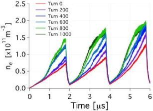
Self-consistent codes are beginning to yield useful results. We present here one such example obtained with the code WARP/POSINST, pertaining to the SPS [61]. In this case, a train of three beam batches, each consisting of 72 bunches, was simulated using a massively parallel computer at NERSC. The goal of the simulation was primarily to assess the impact of the evolution of the proton distribution in the beam on the EC density, as compared to the EC density evolution produced by a build-up code, in which the proton distribution is frozen in time. Fig. 2 shows some of the results of this exercise. The conclusion is that, after 1000 turns, the actual proton distribution leads to a 50–100% increase in the estimate of relative to the case in which the proton distribution is kept frozen at its initial state. While this result is suggestive, it must still be considered preliminary because of the approximations employed, notably that of a constant focusing lattice and the fact that the EC distribution was reinitialized at avery turn (a fully self-consistent simulation, in which both the EC and the proton distributions evolve in time in response to each other has also been carried out [61]).
5 The CESRTA program
A significant, dedicated systematic R&D program to understand the EC and low-emittance tuning has been ongoing at Cornell University for years based on the CESR storage ring. The e+e- collider CESR was decommissioned and the CLEO detector removed. Wigglers were added to the storage ring, along with an extensive array of diagnostic instrumentation intended to analyze the EC. This revamped storage ring (the CESR Test Accelerator, or CESRTA) is intended as a prototype for the damping rings of a possible future e+e- linear collider [62]. A major report will describe the R&D effort in detail [63].
As a test accelerator, CESRTA has unprecedented operational flexibility, specifically:
-
•
Essentially all beam time is devoted to machine studies.
-
•
The injector allows for an almost arbitrary fill pattern.
-
•
The beam species is selectable (e+ or e-), although the two species move in opposite directions in the beam pipe.
-
•
The beam energy is tunable within the range GeV
-
•
The bunch intensity is selectable.
The new diagnostic devices include: retarding-field analyzers (RFA’s) at many locations, magnetized or not; shielded pick-ups (SPU’s); a microwave transmission setup; filtered and gated beam position monitors (BPM’s); etc. In addition, an array of special-purpose devices have been installed including: an in-situ SEY measuring device; a low-magnetic-field chicane, transplanted from PEP-II at SLAC; various sections of beam pipe with low-emission coatings or grooved surfaces; and clearing electrodes. RFA’s allow the measurement of the spatially-resolved, time-averaged, electron flux at the walls of the chamber. The SPU’s allow the measurement of the electron flux at the walls of the chamber with a time resolution of ns. The BPM’s, by themselves or in combination with a beam pinger and a feedback damping system, allow the measurement of bunch-by-bunch frequency spectra and coherent tunes. x-ray beam-size monitors allow the measurement of beam size bunch-by-bunch and turn-by-turn.
As part of the CESRTA R&D, a broad-based program of developing, comparing and benchmarking electron cloud buildup simulation codes, and to a much lesser extent beam dynamics codes, was initiated in 2008 and continues today. Specifically CESRTA input parameters have been used as input to the simulation codes ECLOUD [64, 65], CLOUDLAND [66, 67], POSINST [68, 69], WARP/POSINST [70] and PEHTS [71], and the results compared against measurements. By iterating this process, EC-related parameters that are not well known were pinned down, allowing more reliable extrapolations to the future ILC damping rings. The main parameters that are not well known are those pertaining to the electronic surface properties, i.e. photon reflectivity; photoemission yield or quantum efficiency (QE); photoemission spectrum; and secondary electron yield and spectrum [72].
In addition, a new photon-tracking code, SYNRAD3D [73], has been developed and implemented, which allows the tracking of synchrotron radiation emitted by the beam as it traverses magnetic elements. The code allows for the description of the actual beam size at the emission point, as well as the actual description of the vacuum chamber geometry and external magnetic fields for the entire ring. Models for the photon reflectivity and quantum efficiency have been incorporated. The outcome of this code is the photoelectron emission distribution along the perimeter of the chamber cross section at any desired point in the ring. This photoelectron distribution is fed as an input to the above-mentioned build-up codes. A simpler code of this nature was developed earlier in the context of the LHC EC effort [74].
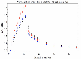
By adjusting the bunch train length and adding a “witness bunch” at various distances after the end of the train, one is able to disentangle the effects of the photoelectrons from the secondary electrons. A comparison of a simulation vs. measurements at CESRTA is shown in Fig. 3 [75].
6 Conclusions
-
•
The ECE is an ubiquitous phenomenon for intense beams. The phenomenon spans a broad range of charged-particle storage rings.
-
•
The ECE is important inasmuch as it limits machine performance, especially for high-intensity future machines.
-
•
The ECE is interesting, as it involves in an essential way various areas of physics, such as: surface geometry and surface electronics; beam intensity and particle distribution; beam energy; residual vacuum pressure in the chamber; certain magnetic features of the storage ring; and other areas.
-
•
Simulation codes are getting better and better in their detailed modeling capabilities and predictive ability.
-
•
Enormous progress has been made since 1995, with a disproportionate credit due to CESRTA and CERN over the past few years. Better and more refined electron detection mechanisms are now deployed. Simulation codes are getting better and better calibrated against measurements.
-
•
Phenomelogical rules of thumb are appearing that tell us the conditions under which the ECE is serious, but not (yet) the conditions under which it s guaranteed to be safe.
7 Epilogue
This workshop is dedicated to the memory of Francesco Ruggiero (1957-2007). I met Francesco on many occasions during my career. I feel honored to have met him and grateful for what I learned from him. I am especially grateful to Francesco for his strong support of electron-cloud R&D effort at CERN and elsewhere. The knowledge that has come out of this program, plus the recent experience at the LHC and SPS, have already greatly benefitted the field as a whole, and will continue to benefit the design and reliability of accelerators worldwide for a long time to come. This workshop is rightfully dedicated to Francesco’s memory.
8 acknowledgments
Over the years I have greatly benefitted from discussions and/or collaboration with many colleagues at ANL, BNL, CERN, Cornell, FNAL, Frascati, KEK, LANL, LBNL, SLAC and TechX—I am grateful to all of them, too numerous to list here. I want to express my special thanks to Roberto Cimino and Frank Zimmermann for organizing this productive and enlightening workshop. We are grateful to NERSC for supercomputer support.
References
- [1] Proc. Intl. Workshop on Collective Effects and Impedance for B Factories “CEIBA95” (KEK, Tsukuba, Japan, 12-17 June 1995; Y. H. Chin, ed.), KEK Proceedings 96-6, August 1996.
- [2] Workshop on Electron Effects in High-Current Proton Rings (SNS/LANL, Santa Fe, NM, 4-7 March 1997), LA-UR-98-1601.
-
[3]
Proc. Intl. Workshop on Multibunch Instabilities in Future Electron and Positron Accelerators “MBI97” (KEK, Tsukuba, Japan, 15-18 July 1997; Y. H. Chin, ed.), KEK Proceedings 97-17, December 1997, http://www-acc.kek.jp/WWW-ACC-exp/Conferences/MBI97-N/
MBI97.html - [4] Proc. Workshop in Instabilities of High Intensity Hadron Beams in Rings “HB1999” (BNL, Upton, NY, June. 28 - July 1, 1999; T. Roser and S.Y. Zhang, eds.), AIP Conf. Proc. 496.
- [5] Proc. 8th Advanced Beam Dynamics ICFA Mini-Workshop on Two-Stream Instabilities in Particle Accelerators and Storage Rings “TwoStream2000” (Santa Fe, NM, 16–18 Feb. 2000; K. Harkay and R. Macek, eds.), http://www.aps.anl.gov//News/Conferences/2000/icfa/two-stream.html
-
[6]
Intl. Workshop on Two-Stream Instabilities in Particle Accelerators and Storage Rings “TwoStream2001” (KEK, Tsukuba, Japan, Sept 11–14, 2001), http://conference.kek.
jp/two-stream/. - [7] Proc. 20th ICFA Advanced Beam Dynamics Workshop on High Intensity High Brightness Hadron Beams “HB2002” (FNAL, April 8–12, 2002; W. Chou and Y. Mori, eds.), http://proceedings.aip.org/proceedings/confproceed/642.jsp
- [8] Proc. Mini-Workshop on Electron-Cloud Simulations for Proton and Positron Beams “ECLOUD02” (CERN, Apr. 15-18, 2002; F. Zimmermann and G. Rumolo, eds.), CERN Yellow Report CERN-2002-001 (2002), http://slap.cern.ch/collective/ecloud02/
- [9] Mini-Workshop on SPS Scrubbing Run Results and Implications for the LHC (CERN, 28 Jun. 2002), http://sl.web.cern.ch/SL/sli/scrubbing-2002/workshop.htm
- [10] 13th ICFA Beam Dynamics Mini-Workshop on Beam-Induced Pressure Rise in Rings “Prise2003” (BNL, Dec. 9-12, 2003), http://www.c-ad.bnl.gov/icfa/
-
[11]
Proc. 31st ICFA Advanced Beam Dynamics Workshop on Electron-Cloud Effects “ECLOUD04” (Napa, California, April 19-23, 2004; M. Furman, S. Henderson and F. Zimmermann, eds.), CERN Yellow Report CERN-2005-001/
CARE-Conf-05-001-HHH/LBNL-56372/SNS-10400000-TR0024-R00, http://icfa-ecloud04.web.cern.ch/icfa-
ecloud04/ -
[12]
Proc. 33rd ICFA Advanced Beam Dynamics Workshop on High Intensity and High Brightness Hadron Beams “HB2004” (Bensheim, Germany, Oct. 18–22, 2004; I. Hofmann and J.-M. Lagniel, eds.). AIP Conf. Proc. 773, BNL-73262-2004-AB (2004), http://www.gsi.de/search/events/
conferences/ICFA-HB2004/index_e.html - [13] Proc. 1st CARE-HHH-APD Workshop on Beam Dynamics in Future Hadron Colliders and Rapidly Cycling High-Intensity Synchrotrons “HHH2004” (CERN, 8–11 November 2004; F. Ruggiero and F. Zimmermann, eds.), http://care-hhh.web.cern.ch/care-hhh/HHH-2004/
-
[14]
39th ICFA Advanced Beam Dynamics Workshop on High Intensity High Brightness Hadron Beams “HB2006” (Epochal Intl. Congress Center, Tsukuba, Japan, May 29 - June 2, 2006), http://hb2006.kek.jp/.
Proceedings: http://accelconf.web.cern.ch/accelconf/abdwhb06/
indexloc.htm - [15] Joint CARE-HHH, CARE-ELAN and EuroTeV Mini-Workshop on Electron-Cloud Clearing “ECL2” (CERN, 1-2 Mar. 2007), http://care-hhh.web.cern.ch/care-hhh/ECL2/
- [16] Proc. Intl. Workshop on Electron-Cloud Effects “ECLOUD07” (Daegu, S. Korea, April 9-12, 2007; H. Fukuma, E. S. Kim and K. Ohmi, eds.), KEK Proceedings 2007-10, Dec. 2007, http://chep.knu.ac.kr/ecloud07/
-
[17]
42nd ICFA Advanced Beam Dynamics Workshop on High-Intensity, High-Brightness Hadron Beams “HB2008” (Nashville, TN, Aug. 25-29, 2008), http://neutrons.ornl.gov/
workshops/hb2008/ -
[18]
CARE-HHH-APD Mini-Workshop on Electron-Cloud Mitigation “ECM08” (CERN, 20-21 Nov. 2008), http://indico.
cern.ch/conferenceDisplay.py?confId=42645 -
[19]
EuCARD-AccNet-EuroLumi Workshop on Anti E-Cloud Coatings That Require no Activation “AEC09” (CERN, 12-13 Oct. 2009), http://indico.cern.ch/conferenceDisplay.py?
confId=62873 -
[20]
46th ICFA Advanced Beam Dynamics Workshop on High-Intensity and High-Brightness Hadron Beams “HB2010” (Morschach, Switzerland, Sep. 27–Oct. 1, 2010), http://
hb2010.web.psi.ch/ -
[21]
49th ICFA Advanced Beam Dynamics Workshop on Electron Cloud Physics “ECLOUD10” (Cornell University, Ithaca, NY, USA, Oct. 8-12, 2010), http://www.lepp.cornell
.edu/Events/ECLOUD10/WebHome.html -
[22]
EuCARD-AccNet CERN-GSI Mini Workshop on Modeling Electron-Cloud Effects (CERN, Geneva, 7-8 Mar. 2011), http://indico.cern.ch/conferenceDisplay.py?ovw=True&
confId=125315 -
[23]
Joint Accelerator Conferences Website, http://www.jacow.
org/ - [24] The Newsletters can be accessed from the ICFA Beam Dynamics Panel website, http://www-bd.fnal.gov/icfabd/
-
[25]
Electron Cloud in the LHC,
http://ab-abp-rlc.web.cern.ch/
ab-abp-rlc-ecloud/ - [26] M. A. Furman, “Formation and Dissipation of the Electron Cloud,” LBNL-51829; Proc. “PAC03,” paper TOPC001.
- [27] G. Rumolo, G. Arduini, E. Métral, E. Shaposhnikova, E. Benedetto, R. Calaga, G. Papotti, and B. Salvant, “Dependence of the Electron-Cloud Instability on the Beam Energy,” Phys. Rev. Lett. 100, 144801 (2008).
- [28] M. A. Furman, “Studies of e-cloud Build-Up for the FNAL Main Injector and for the LHC,” Proc. “HB2006” 14, paper TUAX05.
- [29] R. Cimino, I. R. Collins, M. A. Furman, M. Pivi, F. Ruggiero, G. Rumolo, and F. Zimmermann, “Can Low Energy Electrons Affect High Energy Physics Accelerators?,” CERN-AB-2004-012 (ABP), LBNL-54594, SLAC-PUB-10350, February 9, 2004; Phys. Rev. Lett. 93, 014801 (2004).
- [30] F. Zimmermann, “Electron-Cloud Effects in the LHC,” Proc. “ECLOUD02” [8], p. 47.
- [31] G. Arduini, V. Baglin, T. Bohl, B. Jenninger, M. Jiménez, J.-M. Laurent, D. Schulte, F. Ruggiero, F. Zimmermann, “Electron-cloud build-up simulations and experiments at CERN,” CERN-AB-2004-082, Jul 2004; published: Proc. “EPAC04,” paper WEPLT044.
- [32] M. A. Furman, “Electron-Cloud Build-Up: Theory and Data,” CBP-872/LBNL-4504E (Mar. 25, 2011), Proc. “ECLOUD10” [21].
- [33] F. Zimmermann, “A Simulation Study of Electron-Cloud Instability and Beam-Induced Multipacting in the LHC,” SLAC-PUB-7425, LHC Project Report 95, 27 February 1997.
- [34] G. Rumolo, F. Ruggiero, and F. Zimmermann, “Simulation of the Electron-Cloud Build Up and its Consequences on Heat Load, Beam Stability, and Diagnostics,” PRST-AB 4, 012801 (2001). Erratum: 4, 029901 (2001).
-
[35]
See, for example, the presentations by J. M. Jiménez and G. Rumolo, Proc. LHC Performance Workshop, Chamonix, 2012, https://indico.cern.ch/conferenceDisplay.py?confId=
164089 - [36] R. Cimino, M. Commisso, D. R. Grosso, T. Demma, V. Baglin, R. Flammini and R. Larciprete, “Nature of the Decrease of the Secondary-Electron Yield by Electron Bombardment and its Energy Dependence,” Phys. Rev. Lett. 109, 064801 (2012).
- [37] R. Larciprete, D. R. Grosso, M. Commisso, R. Flammini and R. Cimino, “Secondary Electron Yield of Cu Technical Surfaces: Dependence on Electron Irradiation,” PRST-AB 16, 011002 (2013).
- [38] K. Kennedy, B. Harteneck, G. Millos, M. Benapfl, F. King and R. Kirby, “TiN Coating of the PEP-II Low-Energy Ring Aluminum Arc Vacuum Chambers,” Proc. “PAC97,” paper 8C009 (p. 3568).
- [39] P. He, H.C. Hseuh, M. Mapes, R. Todd and D. Weiss, “Development of Titanium Nitride Coating For SNS Ring Vacuum Chambers,” Proc. “PAC01,” paper WPAH034 (p. 2159).
- [40] W. Fischer, M. Blaskiewicz, J. M. Brennan, H. Huang, H. C. Hseuh, V. Ptitsyn, T. Roser, P. Thieberger, D. Trbojevic, J. Wei, S. Y. Zhang, and U. Iriso, “Electron cloud observations and cures in the Relativistic Heavy Ion Collider,” PRST-AB 11, 041002 (2008).
- [41] H. C. Hseuh, M. Mapes, L. A. Smart, R. Todd and D. Weiss, “Upgrade of RHIC Vacuum Systems for High Luminosity Operation,” Proc. “PAC05,” paper RPPE047.
- [42] Y. Suetsugu, K. Kanazawa, K. Shibata, H. Hisamatsu, K. Oide, F. Takasaki, R. V. Dostovalov, A. A. Krasnov, K. V. Zolotarev, E. S. Konstantinov, V. A. Chernov, A. E. Bondar, A. N. Shmakov, “First experimental and simulation study on the secondary electron and photoelectron yield of NEG materials (Ti-Zr-V) coating under intense photon irradiation,” NIMPR A 554 (2005) 92-113.
- [43] Y. Suetsugu , K. Kanazawa, K. Shibata, H. Hisamatsu, “Continuing study on the photoelectron and secondary electron yield of TiN coating and NEG (Ti-Zr-V) coating under intense photon irradiation at the KEKB positron ring,” NIMPR A 556 (2006) 399-409.
- [44] Y. Suetsugu, K. Kanazawa, K. Shibata and H. Hisamatsu, “Continued Study on Photoelectron and Secondary Electron Yields of TiN and NEG (Ti-Zr-V) Coatings at the KEKB Positron Ring,” Proc. “PAC07,” paper FRPMN042.
- [45] Y. Suetsugu, K.-I. Kanazawa, K. Shibata, H. Hisamatsu, M. Shirai, “Vacuum System for High-Current e-/e+ Accelerators,” ICFA Beam Dynamics Newsletter No. 48, p. 118 (April 2009).
- [46] LHC Design Report, CERN-2004-003, Vol. 1, p. 346
- [47] E. N. Shaposhnikova, G. Arduini, J. Axensalva, E. Benedetto, S. Calatroni, P. Chiggiato, K. Cornelis, P. Costa Pinto, B. Henrist, J. M. Jiménez, E. Mahner, G. Rumolo, M. Taborelli, C. Yin Vallgren, “Experimental Studies of Carbon Coatings as Possible Means of Suppressing Beam Induced Electron Multipacting in the CERN SPS,” Proc. “PAC09,” paper MO6RFP008.
- [48] C. Yin Vallgren, G. Arduini, J. Bauche, S. Calatroni, P. Chiggiato, K. Cornelis, P. Costa Pinto, E. Métral, G. Rumolo, E. Shaposhnikova, M. Taborelli, G. Vandoni, “Amorphus Carbon Coatings for Mitigation of Electron Cloud in the CERN SPS,” Proc. “IPAC10,” paper TUPD048.
- [49] V. Baglin, I. R. Collins, O. Gröbner, “Photoelectron Yield and Photon Reflectivity from Candidate LHC Vacuum Chamber Materials with Implications to the Vacuum Chamber Design,” CERN-LHC-Project-Report-206, Jul 1998. Proc. “EPAC98,” paper TUP18H.
- [50] G. Stupakov and M. Pivi, “Suppression of the Effective Secondary Emission Yield for a Grooved Metal Surface,” LCC-0145, SLAC-TN-04-045, June 2004; Proc. “ECLOUD04” [11], p. 139.
- [51] Y. Suetsugu, H. Fukuma, K. Shibata, M. Pivi, L. Wang, “Experimental Studies On Grooved Surfaces To Suppress Secondary Electron Emission,” Proc. “IPAC10,” paper TUPD043.
- [52] A. Kulikov, A. Fisher, S. Heifets, J. Seeman, M. Sullivan, U. Wienands and W. Kozanecki, “The Electron Cloud Instability at PEP-II,” Proc. “PAC01,” paper TPPH100 (p. 1903).
- [53] Y. Funakoshi, K. Akai, A. Enomoto, J. Flanagan, H. Fukuma, K. Furukawa, J. Haba, S. Hiramatsu, K. Hosoyama, T. Ieiri, N. Iida, H. Ikeda, S. Kamada T. Kamitani, S. Kato, M. Kikuchi, E. Kikutani, H. Koiso, S. I. Kurokawa, M. Masuzawa, T. Matsumoto, T. Mimashi, T. T. Nakamura, Y. Ogawa, K. Ohmi, Y. Ohnishi, S. Ohsawa, N. Ohuchi, K. Oide, E. A. Perevedentsev, K. Satoh, M. Suetake, Y. Suetsugu, T. Suwada, F. Takasaki, M. Tawada, M. Tejima, M. Tobiyama, S. Uno, Y. Wu, N. Yamamoto, M. Yoshida, S. Yoshimoto, M. Yoshioka and F. Zimmermann, “KEKB Performance,” Proc. “PAC01,” paper RPPH131.
- [54] Y. Suetsugu, H. Fukuma, K. Shibata, M. Pivi and L. Wang, “Demonstration of Electron Clearing Effect by Means of Clearing Electrodes and Groove Structures in High-Intensity Positron Ring,” Proc. “PAC09,” paper FR5RFP068.
- [55] Y. Suetsugu, H. Fukuma, K. Shibata, M. Pivi, and L. Wang, “Beam Tests of a Clearing Electrode for Electron Cloud Mitigation at KEKB Positron Ring,” Proc. “IPAC10,” paper WEOAMH01.
- [56] F.-J. Decker, M. H. R. Donald, R. C. Field, A. Kulikov, J. Seeman, M. Sullivan, U. Wienands and W. Kozanecki, “Complicated Bunch Pattern in PEP-II,” Proc. “PAC01,” paper TPPH126 (p. 1963).
- [57] J.-L. Vay, J. M. Byrd, M. A. Furman, R. Secondo, M. Venturini, J. D. Fox, C. H. Rivetta, W. Höfle, “Simulation of E-Cloud Driven Instability and its Attenuation Using a Feedback System in the CERN SPS,” Proc. “IPAC10,” paper WEOBRA02.
- [58] J. D. Fox, A. Bullitt, T. Mastorides, G. Ndabashimiye, C. Rivetta, O. Turgut, D. Van Winkle, J. Byrd, M. Furman, J-L. Vay, W. Höfle, G. Rumolo, R. De Maria, “SPS Ecloud Instabilities - Analysis of Machine Studies and Implications for Ecloud Feedback” Proc. “IPAC10,” paper WEPEB052.
- [59] R. Macek, A. A. Browman, J. S. Kolski, R. C. McCrady, L. J. Rybarcyk, T. Spickermann, and T. J. Zaugg, “Electron cloud generation, trapping and ejection from quadrupoles at the Los Alamos PSR,” Proc. “ECLOUD10” [21].
-
[60]
CARE HHH Electron Cloud Code Collection, https://
oraweb.cern.ch/pls/hhh/code_website.disp_category?cat_
name=Electron%20Cloud - [61] J.-L. Vay, M. A. Furman and M. Venturini, “Direct Numerical Modeling of E-Cloud Driven Instability of Three Consecutive Batches in the CERN SPS,” LBNL-5479E, Proc. “IPAC12,” paper TUEPPB006.
- [62] M. A. Palmer, M. G. Billing, J. Calvey, S. S. Chapman, J. A. Crittenden, R. Gallagher, S. Gray, S. Greenwald, W. H. Hopkins, D. L. Kreinick, Y. Li, X. Liu, J. A. Livezey, R. Meller, D. P. Peterson, M. Rendina, D. Rice, N. Rider, D. Sagan, J. Sexton, J. P. Shanks, J. Sikora, S. Vishniakou, W. Whitney, T. Wilksen, H. Williams, K. C. Harkay, J. P. Alexander, G. Codner, J. Dobbins, G. Dugan, M. Forster, D. L. Hartill, V. Medjidzade, S. Peck, D. Rubin, E. Smith, K. W. Smolenski, C. R. Strohman, A. Temnykh, M. Tigner, R. Holtzapple, A. Wolski, J. Kandaswamy, Y. He, M. Ross, C.-Y. Tan, R. M. Zwaska, J. W. Flanagan, P. Jain, K.-I. Kanazawa, K. Ohmi, H. Sakai, Y. Suetsugu, J. Byrd, C. M. Celata, J. Corlett, S. De Santis, M. Furman, A. Jackson, R. Kraft, D. V. Munson, G. Penn, D. Plate, A. Rawlins, M. Venturini, M. Zisman, D. Kharakh, M. T. F. Pivi, L. Wang, J. Jones, LBNL-2657E/CBP-828, “The Conversion and Operation of the Cornell Electron Storage Ring as a Test Accelerator (CesrTA) for Damping Rings Research and Development,” Proc. “PAC09,” paper FR1RAI02.
- [63] “The CESR Test Accelerator Electron Cloud Research Program: Phase I Report” (M. A. Palmer, M. G.Billing, G. F. Dugan, M. A. Furman and D. L. Rubin, eds.), to be published.
- [64] D. Schulte and F. Zimmermann, “Electron Cloud Build-Up Simulations using ECLOUD,” Proc. “ECLOUD04” [11], pp. 143–152.
- [65] G. Rumolo and F. Zimmermann, “Electron Cloud Simulations: Beam Instabilities and Wakefields,” PRST-AB 5, 121002 (2002).
- [66] L. F. Wang, H. Fukuma, K. Ohmi, S. Kurokawa, K. Oide and F. Zimmermann, “Numerical Study of the Photoelectron Cloud in KEKB Low Energy Ring with a Three-Dimensional Particle in Cell Method,” PRST-AB 5, 124402 (2002).
- [67] L. F. Wang, “User’s Guide for CLOUDLAND,” KEK Internal 2003-2.
- [68] M. A. Furman and G. R. Lambertson, “The electron-cloud instability in the arcs of the PEP-II positron ring,” LBNL-41123/CBP Note-246, PEP-II AP Note AP 97.27 (Nov. 25, 1997). Proc. “MBI97” [3], p. 170.
- [69] M. A. Furman and M. T. F. Pivi, “Probabilistic model for the simulation of secondary electron emission,” LBNL-49771/CBP Note-415 (Nov. 6, 2002). PRST-AB 5, 124404 (2003).
- [70] J.-L. Vay, C. M. Celata, M. A. Furman, G. Penn, M. Venturini, D. P. Grote and K. G. Sonnad, “Update on Electron-Cloud Simulations Using the Package WARP-POSINST,” Proc. “PAC09,” paper FR5RFP078.
- [71] K. Ohmi, “Particle-in-Cell Simulation of Beam-Electron Cloud Interactions,” Proc. “PAC01,” paper TPPH096.
- [72] See, for example, the contributions by G. Dugan and J. Crittenden, these proceedings.
- [73] G. Dugan and D. Sagan, “SYNRAD3D: Photon Propagation and Scattering Simulation,” Proc. “ECLOUD10” [21], paper PST08.
- [74] F. Zimmermann, “Synchrotron Radiation in the LHC Arcs Monte-Carlo Approach,” LHC Project Note 237, 10 October 2000.
- [75] G. Dugan, M. Billing, K. Butler, J. Crittenden, M. Forster, D. Kreinick, R. Meller, M. Palmer, G. Ramirez, M. Rendina, N. Rider, K. Sonnad, H. Williams, J. Chu, R. Campbell, R. Holtzapple, M. Randazzo, J. Flanagan, K.Ohmi, M. Furman, M. Venturini, and M.Pivi, “Studies at CesrTA of Electron-Cloud-Induced Beam Dynamics for Future Damping Rings,” Proc. “IPAC12,” paper WEYA02.