Visualization of EIS at large potential range – new insights
Abstract
Electrochemical Impedance Spectroscopy (EIS) is an experimental technique largely used in electrochemistry and corrosion studies. However, almost all published papers have just measured the EIS at the corrosion potential, especially for corrosion purposes. This fact limits the capability of the technique. In this paper, a Scilab software was developed which allows the visualization of multiple EIS diagrams regarding the potential, exposure time or experiment run. This procedure was applied to austenitic stainless steels in two electrolytes from cathodic to anodic potentials. The EIS maps with two- or three-dimensions were very useful to depict the evolution of the surface with respect to the large range of applied potential. Some results are shown to highlight the usefulness of this approach as a complementary technique to the DC test performed at a given potential range.
keywords:
Corrosion , Stainless steel , Electrochemical impedance , EIS map , Visualization softwareurl]www.labcor.iprj.uerj.br
1 Introduction
Electrochemical Impedance Spectroscopy (EIS) is a linear technique fundamental to study the mechanisms of the electrochemical corrosion process. In this case, the regulation of a direct potential or current in regions of the E-I plot to obtain diagrams that reflects the surface status is crucial [1]. Indeed, the intensity of electrochemical phenomena is strongly dependent on the potential. Thus, the scan of potential is an ordinary means to obtain the kinetic aspects of interfaces. In this sense, polarization curves show the global stationary response of an electrode, being, consequently, used in almost all corrosion studies. However, these studies frequently measure the AC response (impedance) only at the corrosion potential. Then, they have not correlated the aspects of polarization curves with impedance diagrams for a given potential
The mapping procedure presented here is an attempt to fill this gap for a broad potential range. The mapping shown in this paper is different from the dynamic EIS proposed by Darowicki and co-workers [2]. Their measurement uses a package of few superimposed sine waves with direct potential. The direct potential sweeps at a relatively high rate, therefore the impedance spectra are determined for narrow periods of time. Thus, even a non-stationary process could be measured. On the other hand, the measurement procedure used in the present work is the classic one [3], measuring on a frequency by frequency basis. However, we stressed the advantages for data interpretation when the full spectrum is continuously available for all potential, as present in the polarization curves. Therefore, we believe that this improved technique can be of interest to users, as it was the case of the reference [4] related to optical microscopy, because it allows a better understanding of EIS behavior performed at potential range.
2 Experimental Procedure
Samples of UNS S30400 (304SS) and S31600 (316SS) stainless steels were used in the as-received microstructures. The chemical composition of the steels is shown in Table 1.
| Steel | C | Cr | Cu | Mn | Mo | N | Ni | P | S | Si |
|---|---|---|---|---|---|---|---|---|---|---|
| 304SS | 0.038 | 18.21 | 0.49 | 1.47 | 0.28 | 0.079 | 8.12 | 0.037 | 0.025 | 0.5 |
| 316SS | 0.020 | 16.55 | 0.38 | 1.81 | 2.09 | 0.073 | 10.03 | 0.034 | 0.024 | 0.3 |
Two solutions were employed: one ; and another (), and (). The latter solution has a close to 10. They mimic the seawater and the pore solution of a carbonated concrete with chloride infiltration, respectively. All tests were carried out in aerated electrolyte and under controlled temperature .

The counter-electrode was a platinum grid and a saturated calomel electrode (SCE) was employed as a reference electrode. An open circuit potential (OCP) of one hour was held to allow the steady-state condition to be reached. The staircase potentiostatic polarization curves were carried out starting at up to or up to a specific potential. Steps of were used to perform this scanning. After stabilization time at the new potential, the impedance was measured. Fig. 1 shows the complete potential cycle, i.e, one hour of open circuit, a potential scan from cathodic to anodic region. Eventually, a reversion of potential can be done at vertex point. The average potential rate during the staircase-like scan is , low enough to permit a steady-state measure of impedance performed at a relatively high frequency . If a lower frequency is used, the potential scan rate decreases. In any case, the mapping is obtained at a rate below that of the ordinary polarization curve.
Due to the vast amount of data from the hundreds of diagrams (a typical worksheet has around ten thousand points) specialized software was developed to plot the maps. A software application called EIS-Map was written in the Scilab 5.4.1 language [5, 6] to enable the complete visualization and post-processing of the 2D and 3D impedance spectra in Bode format. Commercial graphing software do not handle such a large amount of data. EIS-Map was used to generate the maps of phase angle and magnitude of the impedance of the desired samples. The EIS-Map software can be downloaded from [6]. A Section of the code to plot the impedance maps is shown below.
Section of the Scilab code to plot impedance maps
It was then possible to render the 2D and 3D plots in a smooth way due to the
parameters of the experiment – steps of and perturbation of – which
enable an even superposition of the diagrams. Moreover, the plot3d1 Scilab
function performs an interpolation of consecutive diagrams.
3 Results and discussion
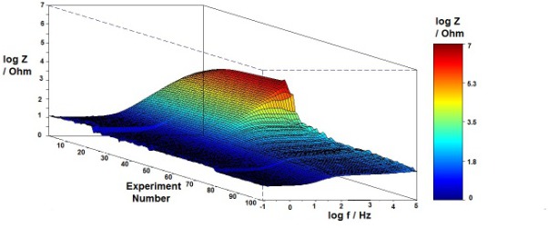
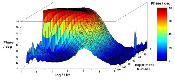
A comprehensive dependency of impedance diagrams on potential can be determined by mapping the magnitude and phase angle. Thus, 75 diagrams were performed consecutively, each one being separated by from the previous ones, as shown in Fig. 2a. The actual E-I plot is depicted in Fig. 2b. This plot is not the polarization curve because it was slightly affected by the sine wave perturbation of , in both potential and the related current data. It nevertheless informs the DC aspects of electrode, such as the cathodic domain, anodic and the pitting.
a b
b
a b
b
The corrosion potential of Figs. 2 and 3 is approximately . The frequency spectrum of high and medium phase angle enlarges with the applied potential. The films formed at anodic potential show better properties as the potential increase, from cathodic to anodic region. Accordingly, the EIS modules behaves similarly. This aspect can be seen on higher modulus as well as a higher angle for a wide frequency span. High angles and moduli are depicted in red color in the maps. Thus, the anodic potential increases and the film quality also increases, even in relation to corrosion potential. However, this applied potential increases the driven-force for the film breakdown. On the other hand, low potential is related to cathodic process intensity since the steels do not corrode, and the impedance depicts the intensity of the cathodic process that takes place on the electrode surface. Beyond the corrosion potential, the surface is under anodic regime and an observable improvement of the film is noted. The frequency range where the angle closer to (red) also alters with potential, from at the corrosion potential to just before the pitting. The spatial localization of corrosion sites also localizes the characteristic frequency range.
Interestingly, the sudden contraction of high-medium (red-yellow) at is more sensible to detect the onset of pitting than the current of Fig. 2b that changes smoothly. The sudden decay of the magnitude, whereas the angle at low frequency approaches a resistive behavior, means that the angle at low frequency approaches zero. The characteristic frequency changes to circa and the maximum angle is around . Moreover, the previous widespread angle distribution, with a true plateau at low frequency, reduces sharply in high potential (Fig. 3b located around ). In Fig. 3 the diagrams are displayed in sequence of diagrams instead of potential.
The reversion of potential occurred at , after a pitting breakdown. This type of mapping allows a complete visualization of impedance for a large potential range. After the pitting, the modulus decays well below and it takes at least to recover high values (c.a. ). The pits are a physical cavity as can be seen in Fig. 4. Moreover, they are electrochemically depressed at a lower potential. A subtle arc (yellow color) from position to is an additional track of repassivation, not available in DC measurement or a single impedance diagram.

Albeit a strong angle scattering near the pitting potential, capacitive angles with low angle at a characteristic frequency around occurs. With the potential reduction, the properties improve again, however, under a discontinuous manner and always with values below those of the corresponding potential of forward scan. For instance, the impedance at after vertex is lower (light yellow, low frequency) than at anodic region (dark red, forward). Fig. 4 shows the optical observation of pitting attack of 304SS after a complete EIS mapping in 3.5% NaCl.

4 Summary
Multiple electrochemical impedances were performed under continuous mode. The potential scan rate was well bellow the usual value in polarization curves, thus a quasi-stationary condition was assumed. Several diagrams were obtained and a special software was implemented to allow a proper visualization of these diagrams, in two and three dimensions. As examples of advantages, the continuous improvement of film in stainless steels corresponding to the potential up to the pitting potential is clearly depicted. Moreover, the inhibition of anodic activity, in the present case related to pitting, can be tracked by the visual impedance display, not available in DC evaluation nor in a single impedance diagram. Thus, by using EIS maps, the flat phase angle exhibited by stainless steels close to corrosion potential changes to a compressed peak at high frequency when pitting is present.
Acknowledgements
The authors thank the Brazilian agencies: CNPq, CAPES, and FAPERJ for the financial support.
References
- [1] M. E. Orazem, B. Tribollet, Electrochemical impedance spectroscopy, Vol. 48, Wiley. com, 2011.
- [2] K. Darowicki, S. Krakowiak, P. Ślepski, Evaluation of pitting corrosion by means of dynamic electrochemical impedance spectroscopy, Electrochimica acta 49 (17) (2004) 2909–2918.
- [3] R. Oltra, M. Keddam, Application of impedance technique to localized corrosion, Corrosion science 28 (1) (1988) 1–18.
- [4] C. M. F. Vieira, S. Paciornik, S. N. Monteiro, Computer controlled digital microscopy—wide area characterization of waste incorporated clay ceramics, Journal of Materials Research and Technology 2 (2) (2013) 202–204.
- [5] INRIA, Scilab numerical programming environment, www.scilab.org.
- [6] R. Fabbri, O. M. Bruno, L. F. Costa, Scilab and SIP for image processing, Arxiv preprint arXiv:1203.4009.