Fractionalized Wave Packets from an Artificial Tomonaga-Luttinger Liquid
The model of interacting fermion systems in one dimension known as Tomonaga-Luttinger liquid (TLL) tomonaga:1950 ; luttinger:1963 provides a simple and exactly solvable theoretical framework, predicting various intriguing physical properties. Evidence of TLL has been observed as power-law behavior in the electronic transport and momentum-resolved spectroscopy on various types of one-dimensional (1D) conductors tarucha:1995 ; bockrathet:1999 ; grayson:1998 . However, these measurements, which rely on dc transport involving tunneling processes, cannot identify the eigenmodes of the TLL, i.e., collective excitations characterized by non-trivial effective charge and charge velocity . The elementary process of charge fractionalization safi:1995 ; pham:2000 ; imura:2002 , a phenomenon predicted to occur at the junction of a TLL and non-interacting leads, has not been observed. Here we report time-resolved transport measurements kamata:2010 on an artificial TLL comprised of coupled integer quantum Hall edge channels berg:2009 , successfully identifying single charge fractionalization processes. An electron wave packet with charge incident from a non-interacting region breaks up into several fractionalized charge wave packets at the edges of the artificial TLL region, from which and can be directly evaluated. These results are informative for elucidating the nature of TLLs and low-energy excitations in the edge channels venkatachalam:2012 .
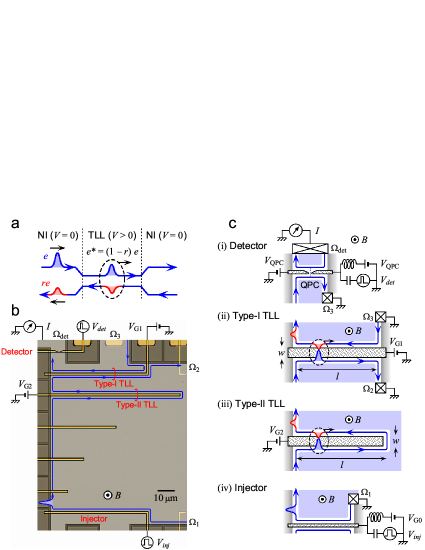
Charge transport in 1D conductors like quantum wires or quantum point contacts (QPCs) are often described by non-interacting electronic modes travelling to the right and left directions wees:1988 . Such a single-particle picture breaks down in the presence of Coulomb interaction, where the system is described by the non-chiral TLL model tomonaga:1950 ; luttinger:1963 and its elementary excitation as collective modes of charge density waves, historically referred to as ‘plasmons’ kane:1992 . The Coulomb interaction enhances the charge velocity in each mode from the Fermi velocity to , where is often used as a measure of the intra-mode interaction. When the counter-propagating modes are coupled to form TLL plasmon modes with a coupling ratio of , the charge velocity is reduced to by the inter-mode interaction chang:2003 . Here we consider a system consisting of two counter-propagating modes (Fig. 1a), which are interacting in the middle (TLL region with ) but not interacting outside the middle region (non-interacting (NI) regions with ). In the interacting region, a transport eigenmode involves charge in the right-moving mode dragging a small amount of charge in the left-moving mode, constituting non-trivial effective charge , which induces various TLL phenomena. However, previous studies searching for such transport eigenmodes have resulted in normal quantized conductance () or a power-law divergence associated with tunneling or scattering of electrons tarucha:1995 ; bockrathet:1999 . Elementary excitation of the charge is expected in the charge fractionalization process safi:1995 ; pham:2000 ; imura:2002 that arises at the junction of NI region () and the TLL region (). When a charge is injected from a NI mode, only a fraction is induced in the TLL region and the rest () should be reflected back in the other NI mode. However, conventional dc measurement cannot detect the fractionalization since similar multiple fractionalizations at the right and left junction completely cancel all traces. We successfully observed such multiple fractionalization processes by means of time-resolved experiments.
We used an artificial TLL consisting of two counter-propagating quantum Hall edge channels berg:2009 . Fig. 1b shows the sample patterned on a GaAs/AlGaAs heterostructure with chiral 1D edge channels formed along the edge of the two-dimensional electronic system (2DES) in a strong perpendicular magnetic field . We conducted measurements with the bulk filling factor between 1 and 2, where a single edge channel with spin-up electrons in the lowest Landau level is formed. The bulk regions with spin-down electrons partially screen the unwanted long-range Coulomb interaction. As shown in Figs. 1c (ii) and (iii), artificial TLL can be formed in a pair of counter-propagating edge channels along both sides of a narrow gate metal. The two channels are designed to have sufficient Coulomb interaction but negligible tunneling effect for a sufficiently large negative gate voltage. Outside the TLL regions, isolated channels formed along the etched regions work effectively as NI chiral leads for injecting and extracting charges from the TLL regions. Two types of TLL regions are investigated; type-I with NI leads on both ends (Fig. 1c (ii)), and type-II with NI leads only on the left and a closed end on the right (Fig. 1c (iii)). We can selectively activate one of the TLL regions by applying appropriate voltages ( and ).
We employed time-resolved charge transport measurement by using high-speed voltage pulses ashoori:1992 ; kamata:2010 . As shown in Fig. 1c (iv), a wave packet with non-equilibrium charge is generated in the NI edge channel by applying a voltage step of the height to the injection gate. The wave packet propagates in the channel as an edge magnetoplasmon (EMP) mode, which is a collective mode with finite fetter:1985 ; volkov:1988 ; talyanskii:1992 . The wave packet introduced into the TLL region undergoes charge fractionalization processes berg:2009 . The reflected charge travels along the outgoing NI lead toward the QPC detector (Fig. 1c (i)) kamata:2010 . All measurements were carried out at about 300 mK.
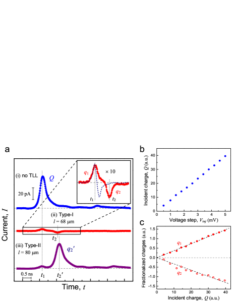
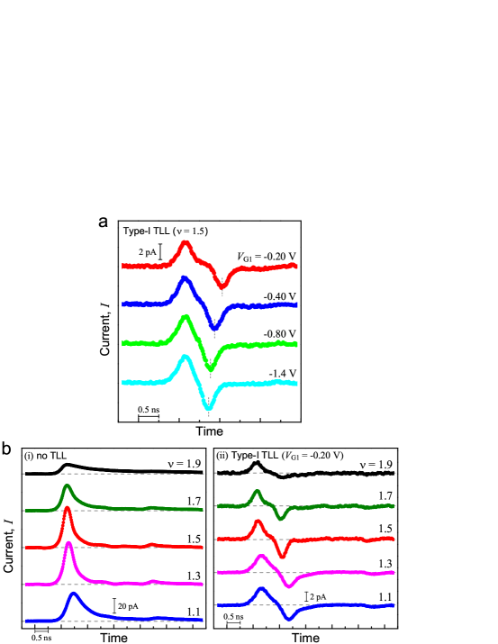
Typical waveforms at ( T) are summarized in Fig. 2a. The top trace (i) represents the incident wave packet measured when no TLL regions are activated with V. The traces (ii) and (iii) show multiple wave packets reflected from Type-I and Type-II TLL regions, respectively (the magnified trace for (ii) is shown in the inset). Both traces have a small positive wave packet at , which is identical to the arrival time of the incident wave packet to the TLL regions. The first fractionalization process at the left junction manifests itself at this timing . TLL theory predicts its charge to be , and our data suggests . The second wave packet shows a small negative peak at in the trace (ii), and a large positive peak at in the trace (iii). The charge in the second wave packet depends on the nature of the right end of the TLL regions. In the case of Type-I TLL region, fractionalization at the right junction and subsequent fractionalization at the left junction should yield the charge in the second wave packet. This is consistent with our observation of more or less equal magnitude with opposite sign of the first and second wave packets in the trace (ii). As for Type-II TLL region, effective charge is fully reflected at the right end, which yields the charge in the second wave packet. This is also consistent with the observation of the large second wave packet in the trace (iii). In this way, the observed wave packets are assigned to charge fractionalization at the both ends of the TLL region.
In order to make our analysis quantitative, the amount of charge in each wave packet is estimated from the area of the waveform. Figure 2b shows the linearity of with respect to . The fractionalized charges and obtained for Type-I TLL region are proportional to (Fig. 2c). The linearity ensures Ohmic connection between the NI leads and the TLL regions. The fractionalization ratio , which is related to the inter-mode interaction parameter in the TLL as safi:1995 ; berg:2009 , and hence, effective charge can be extracted from the slope of vs . Moreover, by measuring the time interval between the two wave packets, which can be regarded as the time of flight for the round trip of the TLL region with length , the effective charge velocity km/s can be obtained when corresponding gate voltages are set at V.
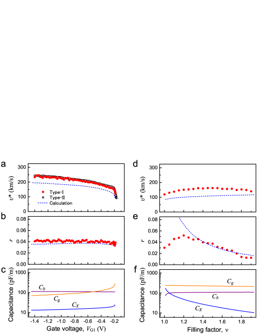
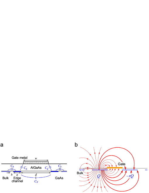
We investigated how the parameters in the artificial TLL change with the gate voltage (Figs. 3a and 3b), and the filling factor (Figs. 3d and 3e). In our artificial TLL, and strongly depend on and , respectively. These variations can be reproduced by considering the Coulomb interactions characterized with the coupling capacitances between the edge channels, , as well as between the channel and the gate metal, , and the bulk region, , as depicted in Fig. 4a. Capacitances obtained from an electrostatic analysis (see Methods) are plotted as functions of and in Figs. 3c and 3f, respectively. We find the TLL parameters represented by the capacitances as
| (1) |
| (2) |
where is used (see Supplementary Information). The good agreements between the calculated values (dashed lines in Figs. 3a, 3b, 3d, and 3e) and the experimental values supports the validity of our analyses and implies that TLL parameters can be designed with the channel structures.
The dependence of the parameters on and can be understood in terms of screening effects. Figure 4b shows a cross-sectional view of typical electric forces (arrows) associated with the transport eigenmode of the TLL. Electrostatic solution indicates that a few lines (thick arrows) of electric force are connected between the edge channels through the GaAs layer while others (thin arrows) are screened by the gate and bulk regions. determines the distance between the edge channel and the gate metal, which significantly modifies and (Fig. 3c). This changes the channel capacitance and , leaving unchanged (Fig. 3b). On the other hand, changes the widths of the compressible and incompressible regions ( and ) chklovskii:1992 ; kumada:2011 , which mainly influence and , leaving and less affected (Figs. 3e and 3f). In this way, and can be tuned separately with and , respectively.
In summary, charge fractionalization at the edges of an artificial TLL region is identified with our time-resolved measurement of charge wave packets. Obtained parameters are consistent with the TLL model as well as microscopic analysis of Coulomb interaction with electrostatic environment. Our measurement scheme and analysis would provide in-depth investigation of interacting electrons in various TLLs as well as quantum Hall edge channels. More generally, the strength of inter-channel interaction changes as a function of the position along the channel. Basically, if the time-resolution is sufficiently high, the measurement could provide time-domain reflectometry of , as the reflection is sensitive to its derivative . The time-domain reflectometry would elucidate various phenomena, such as spin-charge separation in spinfull TLLs lee:1997 ; bocquillon:2013 , chargeless heat transport in integer and fractional quantum Hall regime venkatachalam:2012 , and dissipation processes in coherent electron transport roulleau:2008 .
Appendix A Methods
Calculation for the coupling capacitances. As shown in the cross section of the TLL region in Fig. 4a, the interactions between the conductive regions (gate metal, bulk regions, and edge channels) can be characterized by the coupling capacitances (, , and ). We numerically calculated these capacitances by solving two-dimensional Laplace equation with certain boundary conditions. For simplicity, all conductive regions are assumed to be ideal conductors. The width of the edge channel (compressible region), , and the incompressible gap, , are predetermined from an analytical solution for a similar structure chklovskii:1992 , and the distance between the edge channels, , is also determined from an electrostatic solution larkin:1995 .
References
- (1) Tomonaga, S. Remarks on Bloch’s method of sound waves applied to many-fermion problems. Prog. Theor. Phys. 5, 544 (1950).
- (2) Luttinger, J. M. An exactly soluble model of a many-fermion system. J. Math. Phys. 4, 1154 (1963).
- (3) Tarucha, S., Honda, T. & Saku, T. Reduction of quantized conductance at low temperatures observed in 2 to 10 m-long quantum wires. Solid State Commun 94, 413 (1995).
- (4) Bockrath, M. et al. Luttinger-liquid behaviour in carbon nanotubes. Nature 397, 598 (1999).
- (5) Grayson, M., Tsui, D. C., Pfeiffer, L. N., West, K. W. & Chang, A. M. Continuum of chiral Luttinger liquids at the fractional quantum Hall edge. Phys. Rev. Lett. 80, 1062 (1998).
- (6) Safi, I. & Schulz, H. J. Transport in an inhomogeneous interacting one-dimensional system. Phys. Rev. B 52, R17040 (1995).
- (7) Pham, K.-V., Gabay, M. & Lederer, P. Fractional excitations in the Luttinger liquid. Phys. Rev. B 61, 16397 (2000).
- (8) Imura, K.-I., Pham, K.-V., Lederer, P. & Piéchon, F. Conductance of one-dimensional quantum wires. Phys. Rev. B 66, 035313 (2002).
- (9) Kamata, H., Ota, T., Muraki, K. & Fujisawa, T. Voltage-controlled group velocity of edge magnetoplasmon in the quantum Hall regime. Phys. Rev. B 81, 085329 (2010).
- (10) Berg, E., Oreg, Y., Kim, E.-A. & von Oppen, F. Fractional charges on an integer quantum Hall edge. Phys. Rev. Lett. 102, 236402 (2009).
- (11) Venkatachalam, V., Hart, S., Pfeiffer, L., West, K. & Yacoby, A. Local thermometry of neutral modes on the quantum Hall edge. Nature Phys. 8, 676 (2012).
- (12) van Wees, B. J. et al. Quantized conductance of point contacts in a two-dimensional electron gas. Phys. Rev. Lett. 60, 848 (1988).
- (13) Kane, C. L. & Fisher, M. P. A. Transport in a one-channel Luttinger liquid. Phys. Rev. Lett. 68, 1220 (1992).
- (14) Chang, A. M. Chiral Luttinger liquids at the fractional quantum Hall edge. Rev. Mod. Phys. 75, 1449 (2003).
- (15) Ashoori, R. C., Stormer, H. L., Pfeiffer, L. N., Baldwin, K. W. & West, K. Edge magnetoplasmons in the time domain. Phys. Rev. B 45, 3894 (1992).
- (16) Fetter, A. L. Edge magnetoplasmons in a bounded two-dimensional electron fluid. Phys. Rev B 32, 7676 (1985).
- (17) Volkov, V. A. & Mikhailov, S. A. Edge magnetoplasmons: low frequency weakly damped excitations in inhomogeneous two-dimensional electron systems. Sov. Phys. JETP 67, 1639 (1988).
- (18) Talyanskii, V. I. et al. Spectroscopy of a two-dimensional electron gas in the quantum-Hall-effect regime by use of low-frequency edge magnetoplasmons. Phys. Rev. B 46, 12427 (1992).
- (19) Chklovskii, D. B., Shklovskii, B. I. & Glazman, L. I. Electrostatics of edge channels. Phys. Rev. B 46, 4026 (1992).
- (20) Kumada, N., Kamata, H. & Fujisawa, T. Edge magnetoplasmon transport in gated and ungated quantum Hall systems. Phys. Rev. B 84, 045314 (2011).
- (21) Lee, H. C. & Yang, S.-R. E. Spin-charge separation in quantum Hall edge liquids. Phys. Rev. B 56, R15529 (1997).
- (22) Bocquillon, E. et al. Separation of neutral and charge modes in one-dimensional chiral edge channels. Nature Commun. 4, 1839 (2013).
- (23) Roulleau, P. et al. Direct measurement of the coherence length of edge states in the integer quantum Hall regime. Phys. Rev. Lett. 100, 126802 (2008).
- (24) Larkin, I. A. & Davies, J. H. Edge of the two-dimensional electron gas in a gated heterostructure. Phys. Rev. B 52, R5535 (1995).
Appendix B Acknowledgments
We are grateful to K.-I. Imura and M. Nakamura for fruitful discussions and M. Ueki for experimental support. This work was partially supported by Grants-in-Aid for Scientific Research (21000004, 11J09248) and the Global Center of Excellence Program from the MEXT of Japan through the “Nanoscience and Quantum Physics” Project of the Tokyo Institute of Technology.
Appendix C Author contributions
H.K. performed the experiments, analysed the data and wrote the manuscript. T.F. supervised the research. K.M. grew the wafer. All authors discussed the results and commented on the manuscript.
Appendix D Competing financial interests
The authors declare no competing financial interests.
Appendix E Supplementary information
1. Derivation of equations (1) and (2) in the main manuscript
Wave equation for charge density wave in the form of an edge magnetoplasmon mode can be found in many articles fetter:1985 ; aleiner:1994 ; zhitenev:1995 . Here, we use a simplified yet general form with a channel capacitance defined per unit length, which relates the potential and excess charge density at position along the channel and time as . Associated ‘Hall’ current along the channel changes the charge distribution through the continuity equation . Considering the conductance of the channel , the unidirectional wave equation reads
| (3) |
where gives the charge velocity in uncoupled channels.
Coupled charge density wave in our artificial TLL can be considered in a pair of two counter-propagating edge channels ( for propagating to the positive direction; for negative direction). They are coupled with the cross capacitance per unit length. The relation between the charge density and the potential can be described in a matrix form as
| (4) |
Using the continuity equation, the coupled wave equation for is given by
| (5) |
where and are intra- and inter-channel interaction strengths, respectively. They are given by
| (6) |
| (7) |
The wave equation (5) exhibits transport eigenmode or , which is defined as the coupling factor , and the velocity . Inserting the channel capacitance for the model defined in the main manuscript gives equations (1) and (2).
2. Reflection coefficient
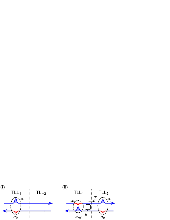
Consider two TLL regions TLL1 and TLL2 with the coupling coefficient and , respectively, connected with each other as shown in Fig. 5. We shall describe the eigenmodes in TLLi as for right moving mode and for left moving mode. Incident wave of amplitude from TLL1 is partially transmitted into the TLL2 with the amplitude and reflected back to TLL1 with the amplitude . Charge conservation law determines a relation
| (8) |
from which we obtain the transmission coefficient and the reflection coefficient . For the abrupt junction between non-interacting channel () and TLL region () defined in Fig. 1a in the main manuscript, we used and to evaluate the reflected charge. The above formula indicates that the reflection is associated with the difference of the coupling coefficients, and can be used to develop a time-domain reflectometry.
3. and dependence of charge waveforms
4. Charge waveforms
It is important to distinguish real signals from spurious ones in Fig. 2a in the main manuscript.
Indeed, the additional small ripples seen at ns and ns in the traces (i) and (iii) are due to ripples in our voltage pulse waveform and irrelevant to the fractionalization processes.
Electrostatic crosstalk between the leads also induces spurious signals in this type of experiments hashisaka:2011 .
However, such crosstalk can be ruled out, as it should appear as a derivative of the incident wave (shown as a dashed line in the inset), which cannot explain our observations.
Although it is also known that plasmon mode exists in the bulk compressible region, such bulk plasmon mode is dissipative and exhibits a lower velocity volkov:1988 .
Therefore, we do not consider the effects from the bulk plasmon mode in the analysis carried out in the main manuscript.
However, we find significant broadening of the peaks for less than 1.3 (Figs. 6b and 6c).
This could be associated with localized bulk regions with fewer electrons.
The scattering of charge density waves by the randomly-distributed localized regions may broaden the waveform guven:2003 ; kumada:2011 .
Another possible reason for the broadening could be the reduced screening effect for long-range Coulomb interaction at smaller .
Our previous results suggest long-range interaction over 100 m near integer filling factors hashisaka:2012 .
In practice, the change in the inter-channel interaction is not as abrupt as illustrated in Fig. 1a in the main manuscript, but smooth in a finite transition length.
The observed width ( ns) in the reflected wave (ii) of Fig. 2a in the main manuscript indicates that the transition length is less than 70 m (the upper bound ignoring other reasons), by assuming identical in the leads and the TLL region.
5. Time-resolved measurement vs dc measurement
In Type-I TLL region (Fig. 1a (ii) in the main manuscript) the NI leads connected to the injection and detection circuits are electrically isolated, so that current should always be zero in dc transport experiments. In our case (the trace (ii) of Fig. 2a in the main manuscript), sum of the charges of all reflected wave packets including higher-order reflection expected at should be zero. Since is small in our device, the higher-order terms are always below the detection limit, and therefore sum of the two wave packets is almost zero within the noise level of our measurement. As for Type-II TLL region (Fig. 1a (iii) in the main manuscript), sum of all charges should be and actually is identical to the incident charge. In this way, multiple fractionalization can only be resolved in time-resolved measurement but not in dc measurements. Another notable feature of our time- resolved measurement is that it does not involve tunneling processes. If the NI leads and the TLL regions are connected through a tunneling barrier, only a fixed charge of rather than arbitrary charge () can be reflected from the TLL region, where individual fractionalization processes cannot be resolved with tunneling experiments.
References
- (1) Fetter, A. L. Edge magnetoplasmons in a bounded two-dimensional electron fluid. Phys. Rev B 32, 7676 (1985).
- (2) Aleiner, I. L. & Glazman, L. I. Novel edge excitations of two-dimensional electron liquid in a magnetic field. Phys. Rev. Lett. 72, 2935 (1994).
- (3) Zhitenev, N. B., Haug, R. J., v. Klitzing, K. & Eberl, K. Linear and nonlinear waves in edge channels. Phys. Rev. B 52, 11277 (1995).
- (4) Hashisaka, M., Washio, K., Kamata, H., Muraki, K. & Fujisawa, T. Interferometric detection of edge magnetoplasmons in AlGaAs/GaAs heterostructures. Phys. Status Solidi C 8, 381 (2011).
- (5) Volkov, V. A. & Mikhailov, S. A. Edge magnetoplasmons: low frequency weakly damped excitations in inhomogeneous two-dimensional electron systems. Sov. Phys. JETP 67, 1639 (1988).
- (6) Güven, K. & Gerhardts, R. R. Self-consistent local equilibrium model for density profile and distribution of dissipative currents in a Hall bar under strong magnetic fields. Phys. Rev. B 67, 115327 (2003).
- (7) Kumada, N., Kamata, H. & Fujisawa, T. Edge magnetoplasmon transport in gated and ungated quantum Hall systems. Phys. Rev. B 84, 045314 (2011).
- (8) Hashisaka, M., Washio, K., Kamata, H., Muraki, K. & Fujisawa, T. Distributed electrochemical capacitance evidenced in high-frequency admittance measurements on a quantum Hall device. Phys. Rev. B 85, 155424 (2012).