STM contrast inversion of the Fe(110) surface
Abstract
We extend the orbital-dependent electron tunneling model implemented within the three-dimensional (3D) Wentzel-Kramers-Brillouin
(WKB) atom-superposition approach to simulate spin-polarized scanning tunneling microscopy (SP-STM) above magnetic surfaces.
The tunneling model is based on the electronic structure data of the magnetic tip and surface obtained from first principles.
Applying our method, we analyze the orbital contributions to the tunneling current, and study the nature of atomic contrast
reversals occurring on constant-current SP-STM images above the Fe(110) surface. We find an interplay of orbital-dependent
tunneling and spin-polarization effects responsible for the contrast inversion, and we discuss its dependence on the bias voltage,
on the tip-sample distance, and on the tip orbital composition.
Keywords: STM imaging, SP-STM, orbital-dependent tunneling, spin-polarized tunneling, atomic contrast reversal, Fe(110)
pacs:
72.25.Ba, 68.37.Ef, 71.15.-m, 73.63.-bI Introduction
The scanning tunneling microscope (STM) is a great equipment to study physical and chemical phenomena on a wide range of material surfaces in high spatial resolution. Its magnetic version, the spin-polarized STM (SP-STM) is one of the main tools for investigating atomic scale magnetism at material/vacuum interfaces wiesendanger09review where the inversion symmetry is broken, giving rise to interesting magnetic phenomena. In order to explain relevant experimental findings on spin-polarized electron transport above magnetic surfaces, advanced and efficient theoretical methods are needed hofer03rmp ; hofer03pssci . Therefore, we propose a computationally efficient spin-polarized electron tunneling model based on the orbital-dependent atom-superposition approach palotas12orb to simulate SP-STM where the electronic structure of the magnetic tip and surface is determined from first principles calculations. We apply the developed method to study the atomic contrast reversal on the Fe(110) surface.
Even in nonmagnetic STM, at certain bias voltage and tip-sample distance ranges, constant-current STM images can show atomic contrast inversion above flat metal surfaces, i.e., the apparent height of surface atoms can be smaller than that of the surface hollow position, and consequently, atoms do not always appear as protrusions on the STM images. This phenomenon was widely studied in the literature mingo96 ; heinze98 ; ondracek12 ; palotas12orb . Chen theoretically explained the corrugation inversion found on low Miller index metal surfaces by the presence of tip states chen92 . For the particular case of the W(110) surface, Palotás et al. palotas12orb highlighted the role of the real-space shape of the electron orbitals involved in the tunneling, including tip states. On the other hand, Heinze et al. heinze98 pointed out that a competition between electron states from different surface Brillouin zone parts is responsible for the corrugation inversion effect. A similar explanation was given on the contrast inversion above the magnetic Fe(001) surface in the presence of an external electric field heinze99 . Following the real-space electron orbital picture, we expect that beside orbital-dependent effects palotas12orb magnetic characteristics also play an important role in the determination of the corrugation quality of SP-STM images on magnetic surfaces. This expectation is supported by the reported bias voltage dependent magnetic contrast reversals in two different magnetic systems yang06 ; palotas11stm obtained by using spherical tunneling models. Note that the magnetic effect can be tuned in different ways, e.g., the magnetic contrast can be enhanced by properly adjusting the bias voltage and/or the tip magnetization direction palotas13contrast , or by using chemically modified magnetic STM tips hofer08tipH .
In the present work we report the formalism capable of studying the interplay of orbital-dependent and spin-polarized tunneling effects within the three-dimensional (3D) Wentzel-Kramers-Brillouin (WKB) theory, and investigate the atomic contrast reversal on the Fe(110) surface.
II Spin-polarized orbital-dependent tunneling model within the 3D WKB theory
In SP-STM the total tunneling current can be written as the sum of a non-spin-polarized, , and a spin-polarized part, , i.e., wortmann01 ; hofer03 ; smith04 ; heinze06 ; palotas11stm . We combine this concept with the orbital-dependent electron tunneling model palotas12orb within the 3D WKB framework based on previous atom-superposition theories tersoff85 ; yang02 ; smith04 ; heinze06 . Using the nonmagnetic version of this orbital-dependent method provided comparable STM images of the W(110) surface with those obtained by standard Tersoff-Hamann tersoff83 ; tersoff85 and Bardeen bardeen61 tunneling models implemented in the BSKAN code hofer03pssci ; palotas05 . The advantages, particularly computational efficiency, limitations, and the potential of the 3D WKB method were discussed in Ref. palotas13fop .
The model assumes that electron tunneling occurs through one tip apex atom only, and the transitions between this apex atom and a suitable number of sample surface atoms are superimposed palotas11sts ; palotas12orb . Since each transition is treated within the one-dimensional (1D) WKB approximation, and the 3D geometry of the tunnel junction is considered, the method is, in effect, a 3D WKB approach. The electronic structure of the magnetic tip and surface is included via the atom-projected electron density of states (PDOS) obtained by ab initio electronic structure calculations. Both the charge and magnetization PDOS are necessary to describe spin-polarized tunneling palotas11stm , and the orbital-decomposition of the PDOS is essential for the description of the orbital-dependent tunneling palotas12orb .
Assuming elastic tunneling and K temperature, the non-spin-polarized (TOPO) and spin-polarized (MAGN) parts of the tunneling current measured at bias voltage at the tip position can be written as
| (1) | |||
| (2) |
The corresponding integrand can be written as a superposition of individual atomic contributions from the sample surface (sum over ):
Here, is the elementary charge, is the Planck constant, and and are the Fermi energies of the sample surface and the tip, respectively. The factor gives the correct dimension (A/V) of the formal conductance-like quantities palotas12sts . The value of has to be determined by comparing the simulation results with experiments, or with calculations using more sophisticated methods, e.g., the Bardeen approach bardeen61 . We chose eV palotas12orb that gives comparable current values with those obtained from the Bardeen method. Note that the choice of has no qualitative influence on the reported results. and are the orbital-decomposed charge PDOS functions of the th sample surface atom and the tip apex atom with orbital symmetry and , respectively. Similarly, and are the corresponding energy-dependent magnetization PDOS vectors. These quantities are needed in Eqs.(II) and (II), respectively, and they can be obtained from a suitable electronic structure calculation. In collinear magnetic systems and with , where is the unit vector of the spin quantization axis palotas11stm . The corresponding total charge or magnetization PDOS is the sum of the orbital-decomposed contributions: , , , . Note that a similar decomposition of the Green functions was employed within the linear combination of atomic orbitals (LCAO) framework in Ref. mingo96 .
The sum over and in Eqs.(II) and (II) denotes the superposition of the effect of atomic orbitals of the sample surface and the tip, respectively, via an orbital-dependent tunneling transmission function: gives the probability of the electron tunneling from the orbital of the th surface atom to the orbital of the tip apex atom, or vice versa. The transmission probability depends on the energy of the electron , the bias voltage , and the relative position of the tip apex and the th sample surface atom . In our model we consider atomic orbitals, and the following form for the transmission function:
| (5) |
Here, the exponential factor corresponds to an orbital-independent transmission where all electron states are considered as exponentially decaying spherical states tersoff83 ; tersoff85 ; heinze06 , and it depends on the distance and on the vacuum decay . We assume an effective rectangular potential barrier in the vacuum between the sample and the tip. and are the electron work functions of the sample surface and the tip, respectively, is the electron’s mass, and is the reduced Planck constant. The remaining factors of Eq.(5) are responsible for the orbital-dependence of the transmission function. They modify the exponentially decaying part according to the real-space shape of the electron orbitals involved in the tunneling, i.e., the angular dependence of the electron densities of the atomic orbitals of the surface and the tip is considered by the square of the real spherical harmonics . , , and can be calculated for each surface atom from the actual tip-sample geometry: , , . For more details, please see Ref. palotas12orb .
From Eqs.(1)-(II) it is clear that the total tunneling current can be decomposed according to orbital symmetries: . The absolute current contribution of the transition can be calculated as
while the relative contribution can be obtained as
| (7) |
Note that the method can also be combined with arbitrary tip orientations mandi13tiprot to study tip rotation effects on SP-STM images above magnetic surfaces, and an orbital-dependent atom-superposition model for the spin-polarized scanning tunneling spectroscopy (SP-STS) palotas11sts ; palotas12sts can also be developed.
III Computational details
Using the presented spin-polarized orbital-dependent tunneling model, we study the atomic contrast reversal on the SP-STM images of the Fe(110) surface. We particularly focus on tip effects, and consider ideal magnetic tip models with different orbital symmetries, and a more realistic iron tip. The effect of three different tip magnetization orientations is also investigated. We choose 27 Fe(110) surface atoms involved in the atomic superposition in combination with the ideal tips, and 112 Fe(110) surface atoms combined with the iron tip including the simulation of SP-STM images.
We performed geometry relaxation and electronic structure calculations within the generalized gradient approximation (GGA) of the density functional theory (DFT) implemented in the Vienna Ab-initio Simulation Package (VASP) VASP2 ; VASP3 ; hafner08 . A plane wave basis set for electronic wave function expansion in combination with the projector augmented wave (PAW) method kresse99 was applied, and the exchange-correlation functional is parametrized by Perdew and Wang (PW91) pw91 . The electronic structures of the sample surface and the tip were calculated separately.
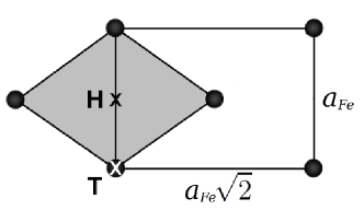
We model the Fe(110) surface by a slab of nine atomic layers with the theoretically determined lattice constant of Å, obtained at the total energy minimum of a bulk body-centered-cubic Fe cell, in agreement with Ref. jiang03 . In the surface slab calculations we set up a separating vacuum region of 24 Å width in the surface normal () direction between neighboring supercell slabs to minimize slab-slab interaction. After geometry relaxation the Fe-Fe interlayer distance between the two topmost layers is reduced by 0.39%, and the underneath Fe-Fe interlayer distance is increased by 0.36% in comparison to bulk Fe. These are in excellent agreement with the findings of Ref. jiang03 : -0.36%, and +0.46%, respectively. The size of the in-plane magnetic moment of the surface Fe atoms is 2.50 , in agreement with Refs. heinze98 ; jiang03 . The unit cell of the Fe(110) surface (shaded area) and the rectangular scan area for the tunneling current simulations are shown in Figure 1 where the surface top (T) and hollow (H) positions are explicitly indicated. The average electron work function above the Fe(110) surface is eV calculated from the local electrostatic potential. We used a Monkhorst-Pack monkhorst k-point grid for obtaining the orbital-decomposed projected charge and magnetization electron DOS onto the surface Fe atom, and , respectively.
Within the presented spin-polarized orbital-dependent tunneling approach ideal magnetic tip models with particular orbital symmetries can be considered, i.e., orbital symmetry corresponds to the energy-independent choice of and . Another characteristic for ideal magnetic tips is that their absolute spin polarization is maximal () in the full energy range, i.e., combined with a particular orbital symmetry: ( is the unit vector of the tip spin quantization axis that is parallel to the assumed tip magnetization direction, an input parameter in our method) and . We took tip orbital symmetries. For the ideal tips we used vacuum decay in Eq.(5).
More realistic tips can be employed by explicitly calculating the orbital decomposition of the tip apex PDOS in model tip geometries. In the present work a blunt iron tip is used, where a single Fe apex atom is placed on the hollow position of the Fe(001) surface, similarly as in Ref. ferriani10tip . We took an Fe(001) slab consisting of nine atomic layers with the theoretically determined lattice constant of Å, and placed an adatom on each side of a surface cell. A separating vacuum region of 20 Å width in the surface normal direction was chosen to minimize slab-slab interaction. After geometry relaxation of the adatom and the first surface layer performed by the VASP code, the orbital-decomposed electronic structure data projected to the tip apex atom, and , were calculated using a Monkhorst-Pack k-point grid. We obtained the local electron work function of eV above the iron tip apex atom that was used in the tunneling simulations.
IV Results and discussion
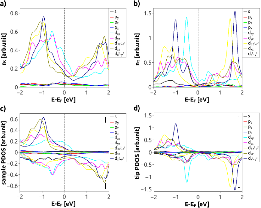
Figure 2 shows the energy-dependent orbital-decomposed charge () and spin-resolved () PDOS functions of the Fe(110) surface atom (S) and the Fe(001) tip apex atom (T) as follows: Fig. 2a) , Fig. 2b) , Fig. 2c) , Fig. 2d) , with . We find that the partial PDOS is dominating over and partial PDOS with the exception of the majority spin () PDOS above the Fermi levels. The obtained results are in good agreement with Refs. heinze98 ; ferriani10tip , where the full potential linearized augmented plane wave (FLAPW) method was employed.
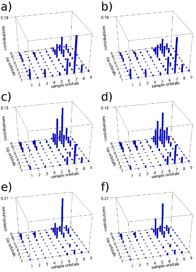
The relative contributions of all orbital-dependent transitions to the total tunneling current, , can be calculated according to Eq.(7). Figure 3 shows representative histograms at different bias voltages and iron tip positions above the Fe(110) surface. We set the tip magnetization parallel to the in-plane Fe(110) surface magnetic moment. Parts a) and b) of Figure 3 correspond to the tip apex Å above the surface top (T) and hollow (H) positions, respectively (for T and H see Figure 1), and the bias voltage is set to = -0.1 V. We find that the tip (1) orbital provides the dominating contributions combined with the sample (6) and (7) orbitals. The (7-7) and (6-6) transitions also give sizeable contributions. The main difference between the T and H tip positions is that above the Fe(110) hollow site the (6-7 and 7-6) contributions gain, while the (7-7) contribution loses weight, similarly to the finding above the W(110) surface palotas12orb . This is due to the different orientational overlap of the mentioned tip and sample orbitals at the two tip positions, and it is not affected by the bias voltage. On the other hand, at a larger negative bias = -1.0 V [Figure 3c) and 3d)] we observe that the tip (1) orbital loses and the (6), (7), and (8) orbitals and their tip-sample combinations gain weight. The largest contribution is now found for the (7-7) transition. We find an enhancement of this effect at = -2.0 V [Figure 3e) and 3f)], and here the tip (1) orbital contributions are tiny. This bias-trend can be explained by the surface and tip partial charge PDOS in Figure 2. At large negative bias voltages the combination of the surface occupied partial PDOS with the tip unoccupied partial PDOS clearly dominates over the tip partial contributions. We find similar trends for a tip magnetization perpendicular to the surface, and also for positive bias voltages (consider the combination of the surface unoccupied with the tip occupied partial charge PDOS in Figure 2).
As demonstrated in Ref. palotas12orb , the current difference between tip positions above the top (T) and hollow (H) surface sites is indicative for the corrugation character of a constant-current STM image. The total () current difference at tip-sample distance and bias voltage is defined as
| (8) |
Positive corresponds to an STM image with normal corrugation where the atomic sites appear as protrusions, and negative to an inverted STM image with anticorrugation and atomic sites appearing as depressions. The contour gives the combinations where the corrugation inversion occurs.
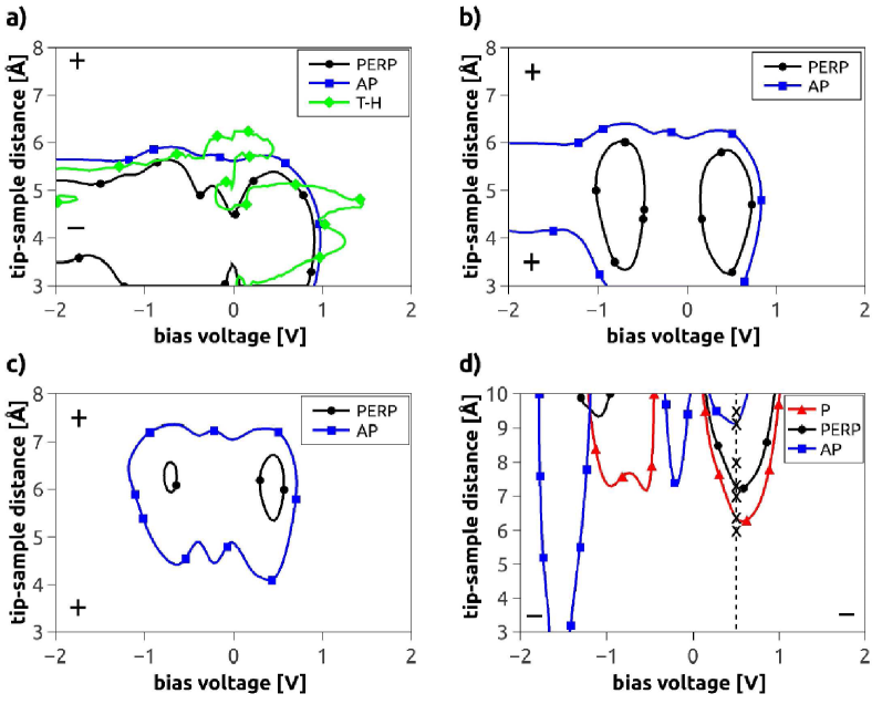
Figure 4 shows such zero current difference contours calculated with four different tip models and three tip magnetization orientations [parallel (P), perpendicular (PERP), and antiparallel (AP) with respect to the Fe(110) surface magnetic moment] in the [-2 V, +2 V] bias voltage range. We consider the [3 Å, 8 Å] tip-sample distance regime in Figs. 4a), 4b), and 4c) for the ideal tips with , , and orbital character, respectively, and the [3 Å, 10 Å] range in Fig. 4d) for the iron tip. Note that the validity of our tunneling model is restricted to about Å.
Let us first focus on the zero current difference contours obtained by the -tip in Fig. 4a). The contrast inversion of the Fe(110) surface with an -tip at a fixed Å tip-sample distance was already studied with a different theoretical approach by Heinze et al. in Ref. heinze98 . Comparing these results with ours we find good qualitative agreement: The P tip magnetization does not show any contrast inversion in the studied range. This corresponds to the majority spin data of Fig. 15 in Ref. heinze98 . On the other hand, the PERP and AP tip magnetizations result in curves shifted away from each other, and the direction of the shift qualitatively agrees with the findings of Ref. heinze98 . Note, however, that the corrugation inversions at Å are found at different bias voltages: 0.87 V (our model, PERP) vs. 0.4 V (Total, Fig. 15 in Ref. heinze98 ), and 0.94 V (our model, AP) vs. 0.7 V (minority spin, Fig. 15 in Ref. heinze98 ). This difference can be attributed to the nonequal lattice constants used and the different theoretical approaches.
As a further test of the reliability of our tunneling model, we compared the contour using the PERP tip magnetization with that obtained by the Tersoff-Hamann method, the curve denoted by T-H in Fig. 4a). We find that our model reproduces the region with the inverse corrugation denoted by the ’’ sign qualitatively well. Quantitative agreement is not present due to the approximations in the 3D WKB method palotas13fop . Note that the PERP tip magnetization corresponds to an equal 0.5-0.5 weighting of the majority and minority spin channels contributing to the tunneling and, thus, to a zero spin-polarized () contribution of the current (, ), and solely orbital-dependent effects play a role in the tunneling without spin-polarization effects.
Altogether, the results obtained by the -tip indicate that the Fe(110) surface always appears to be normally corrugated taking a P tip magnetization with respect to the surface magnetic moment, whereas changing the tip magnetization to PERP and AP result in anticorrugation below about 1 V bias and 6 Å tip-sample distance.
To understand these results, we give the following interpretation: It is known that there is a competition between the tunneling contributions from (, , ) and orbitals in the formation of the corrugation character of an STM image chen92 ; palotas12orb . Generally, states prefer normal corrugation, whereas states prefer anticorrugation. Based on our model, we suggest that the corrugation inversion can be understood as an interplay of the real-space orbital shapes involved in the tunneling and their corresponding energy-dependent partial PDOS. For the PERP [Fig. 2a)] and AP [minority spin () in Fig. 2c)] cases the partial PDOS of the Fe(110) surface is dominating over the and partial PDOS in the whole energy range. Therefore, considering only orbital shapes of the surface, the leading current contribution is expected from the orbital of the underlying Fe atom when the tip is placed above the surface T position, and from the , orbitals of the four nearest-neighbor surface Fe atoms when the tip is above the surface H position. Note that the weight of is larger than of due to the geometry of the (110) surface, see Fig. 1. By changing the tip-sample distance there is a competition between the contributions of these states due to the orbital-dependent transmission in Eq. 5, and there is a range ( Å) where dominates over , thus anticorrugation is obtained. At large distances the orbitals lose and the orbital gains importance, and normal corrugation is found. This simple orbital-picture has to be combined with the energy-dependence of the PDOS of the contributing spin channels for an accurate interpretation. As can be seen in Figs. 2a) and 2c) (), there is a large -type PDOS peak at about 1.5 eV above the Fermi level. The existence of this PDOS feature results in the disappearance of the anticorrugated region above around 1 V. Note that although the -type PDOS is comparable in size with the -type PDOS in this energy range, the weighted contribution of orbitals is much smaller due to the orbital shapes and the tip-sample geometry. For the P tip magnetization, below the Fermi level the orbital-shape-weighted contribution of is dominating compared to , for the PDOS see Fig. 2c) (). Above the Fermi level the importance of the states decreases rapidly, and concomitantly and states gain more importance, resulting in normal corrugation in the full energy and tip-sample distance range.
Comparing Figs. 4a), 4b), and 4c) we find that the anticorrugation regime is shifted to larger tip-sample distances following the order , , and , similarly as found for the W(110) surface palotas12orb . This is due to the increasingly localized character of these tip orbitals in the -direction. It means that the dominating current contributions originate from less and less surface atoms that are located directly below the tip position. Considering the orbital-dependent transmission in Eq. 5 and these -localized () tip orbitals, it follows naturally that the maximal effect of the surface orbitals preferring anticorrugation is found at larger tip-sample distances. On the other hand, there are certain energy regimes where this orbital overlap effect results in the occurrence of normal corrugation since the complex competition between and surface orbitals weighted with their partial PDOS is won by the corrugating state. For all considered ideal magnetic tips the P tip magnetization corresponding to the majority spin channel does not show any contrast inversion in the studied range. Taking the PERP and AP tip magnetization directions we expect normal corrugation above approximately 1.0 V (-tip), 0.9 V (-tip), and 0.8 V (-tip) irrespective of the tip-sample distance. The reasons are outlined above, and see the discussion for the -tip. The series of Figs. 4a), 4b), and 4c) demonstrate the orbital-dependent tunneling and tip orbital effects on the corrugation inversion.
Taking the iron tip having all nine orbital characters with weighted energy-dependent PDOS, it is clearly seen in Fig. 4d) that the contours are considerably affected by the tip electronic structure. We find that all considered tip magnetization directions result in the appearance of corrugation inversions in the studied bias voltage and tip-sample distance range. Close to the surface anticorrugation is observed for the same reason as discussed for the -tip, with the exception of the approximate [-1.7 V, -1.4 V] range where the AP tip magnetization shows normal corrugation and no inversion at all. The reasons for this finding are the observed peaks in the surface majority spin () PDOS at around 1 eV and 1.5 eV below the sample Fermi energy and the tip minority spin () PDOS at around 1.5 eV above the tip Fermi level, see Figs. 2c) and 2d). Such a combination of electronic structures gives a robust normal corrugation in the given bias range. By moving the tip away from the surface, contrast inversions are indicated by the contours at large tip-sample distances, i.e., the anticorrugation () changes to normal corrugation (). It is clearly seen that these inversion contours vary considerably depending on the tip magnetization orientation. This is due to the complex combined effect of the orbital-dependent tunneling and spin-polarization originating from the electronic structures of the sample surface and the tip. For instance, the minority spin () PDOS peak of the tip located at 0.5 eV below its Fermi level in Fig. 2d) is mainly responsible for the set of observed inversions at around 0.5 V bias. The tip orbital prefers normal corrugation in the studied tip-sample distance range due to its and nodal planes since above the H position the anticorrugating surface orbitals do not contribute to the current, and is expected to be larger than palotas12orb . Considering other orbital contributions weighted with their partial PDOS, however, results in anticorrugation below about Å. In effect, we point out that the complex interplay of the real-space orbital shapes and the energy-dependent PDOS of the contributing spin channels of both the surface and the tip results in the observed corrugation inversion maps in Fig. 4. The above findings demonstrate the tunability of the height of the observable atomic contrast inversion depending on the spin-polarized tunneling via the tip magnetization orientation.
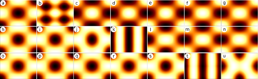
In order to show the dependence of the atomic contrast inversion on the tip-sample distance and on the tip magnetization orientation more apparently, constant-current SP-STM images are simulated. We choose the iron tip and the bias voltage of 0.5 V. The total tunneling current () is calculated in sheets of 0.01 Å vertical width centered at seven selected tip heights between 6 and 9.5 Å marked by crosses in Fig. 4d) above the rectangular scan area shown in Figure 1. The lateral resolution is 0.04 Å by taking points in each sheet. The constant-current contours are extracted following the method described in Ref. palotas11stm . Figure 5 shows the simulated constant-current SP-STM images of the Fe(110) surface at seven apparent heights of the surface Fe atom (seven columns) and three magnetic orientations of the iron tip (three rows): parallel (P, first row: a-g), perpendicular (PERP, second row: h-n), and antiparallel (AP, third row: o-u) to the Fe(110) surface magnetic moment. The apparent heights of the Fe atom and the current values of the contours are given in the caption of Figure 5. Going from the left to the right in Figure 5, the current value is decreasing with a concomitant movement of the tip farther from the surface. It can clearly be seen that the contrast inversion occurs at different tip heights depending on the tip magnetization orientation: P, 6.37 Å (b); PERP, 7.28 Å (k); AP, 9.12 Å (t), see also Fig. 4d). We find that the SP-STM image of the contrast inversion with P tip magnetization orientation (Fig. 5b) is markedly different from the striped images in the PERP and AP case (Figs. 5k and 5t, respectively). Such striped STM images of the contrast inversion were also reported above the nonmagnetic W(110) surface palotas12orb . Note, however, that in experiments the atomic resolution is lost close to the inversion heinze98 . Below the inversion we observe anticorrugation (Figs. 5a, h-j, o-s), i.e., the surface atoms appear as depressions, and above the inversion normal corrugation is obtained (Figs. 5c-g, l-n, u), in accordance with Fig. 4d).
V Conclusions
We extended the orbital-dependent electron tunneling model implemented within the three-dimensional (3D) Wentzel-Kramers-Brillouin (WKB) atom-superposition approach to simulate spin-polarized scanning tunneling microscopy (SP-STM) above magnetic surfaces. Applying our method, we analyzed the bias-dependence of the orbital contributions to the tunneling current above the Fe(110) surface, and found a shift of the relevant tip contributions close to zero bias toward tunneling at higher bias. We showed that spin-polarized tunneling has a considerable effect on the tip-sample distance where atomic contrast inversion occurs, and the tip magnetization direction and tip orbital composition play a crucial role as well. Taking an -tip, our findings showed qualitative agreement with the Tersoff-Hamann method and with Ref. heinze98 concerning the corrugation character of the Fe(110) surface. We explained our results based on the complex interplay of the real-space orbital shapes involved in the tunneling and the energy-dependent orbital-decomposed PDOS of the sample and the tip. Finally, we demonstrated the contrast inversion by simulating SP-STM images.
VI Acknowledgments
Financial support of the Magyary Foundation, EEA and Norway Grants, the Hungarian Scientific Research Fund (OTKA PD83353, K77771), the Bolyai Research Grant of the Hungarian Academy of Sciences, and the New Széchenyi Plan of Hungary (Project ID: TÁMOP-4.2.2.B-10/1–2010-0009) is gratefully acknowledged. Usage of the computing facilities of the Wigner Research Centre for Physics, and the BME HPC Cluster is kindly acknowledged.
References
- (1)
- (2) R. Wiesendanger, Spin mapping at the nanoscale and atomic scale, Rev. Mod. Phys. 81 (2009) 1495-1550.
- (3) W.A. Hofer, A.S. Foster, A.L. Shluger, Theories of scanning probe microscopes at the atomic scale, Rev. Mod. Phys. 75 (2003) 1287-1331.
- (4) W.A. Hofer, Challenges and errors: interpreting high resolution images in scanning tunneling microscopy, Prog. Surf. Sci. 71 (2003) 147-183.
- (5) K. Palotás, G. Mándi, L. Szunyogh, Orbital-dependent electron tunneling within the atom superposition approach: Theory and application to W(110), Phys. Rev. B 86 (2012) 235415.
- (6) N. Mingo, L. Jurczyszyn, F.J. Garcia-Vidal, R. Saiz-Pardo, P.L. de Andres, F. Flores, S.Y. Wu, W. More, Theory of the scanning tunneling microscope: Xe on Ni and Al, Phys. Rev. B 54 (1996) 2225-2235.
- (7) S. Heinze, S. Blügel, R. Pascal, M. Bode, R. Wiesendanger, Prediction of bias-voltage-dependent corrugation reversal for STM images of bcc (110) surfaces: W(110), Ta(110), and Fe(110), Phys. Rev. B 58 (1998) 16432-16445.
- (8) M. Ondráček, C. González, P. Jelínek, Reversal of atomic contrast in scanning probe microscopy on (111) metal surfaces, J. Phys. Condens. Matter 24 (2012) 084003.
- (9) C.J. Chen, Effects of m0 tip states in scanning tunneling microscopy: The explanations of corrugation reversal, Phys. Rev. Lett. 69 (1992) 1656-1659.
- (10) S. Heinze, X. Nie, S. Blügel, M. Weinert, Electric-field-induced changes in scanning tunneling microscopy images of metal surfaces, Chem. Phys. Lett. 315 (1999) 167-172.
- (11) R. Yang, H. Yang, A.R. Smith, A. Dick, J. Neugebauer, Energy-dependent contrast in atomic-scale spin-polarized scanning tunneling microscopy of Mn3N2(010): Experiment and first-principles theory, Phys. Rev. B 74 (2006) 115409.
- (12) K. Palotás, W.A. Hofer, L. Szunyogh, Simulation of spin-polarized scanning tunneling microscopy on complex magnetic surfaces: Case of a Cr monolayer on Ag(111), Phys. Rev. B 84 (2011) 174428.
- (13) K. Palotás, Prediction of the bias voltage dependent magnetic contrast in spin-polarized scanning tunneling microscopy, Phys. Rev. B 87 (2013) 024417.
- (14) W.A. Hofer, K. Palotás, S. Rusponi, T. Cren, H. Brune, Role of hydrogen in giant spin polarization observed on magnetic nanostructures, Phys. Rev. Lett. 100 (2008) 026806.
- (15) D. Wortmann, S. Heinze, P. Kurz, G. Bihlmayer, S. Blügel, Resolving complex atomic-scale spin structures by spin-polarized scanning tunneling microscopy, Phys. Rev. Lett. 86 (2001) 4132-4135.
- (16) W.A. Hofer, A.J. Fisher, Simulation of spin-resolved scanning tunneling microscopy: influence of the magnetization of surface and tip, J. Magn. Magn. Mater. 267 (2003) 139-151.
- (17) A.R. Smith, R. Yang, H. Yang, W.R.L. Lambrecht, A. Dick, J. Neugebauer, Aspects of spin-polarized scanning tunneling microscopy at the atomic scale: experiment, theory, and simulation, Surf. Sci. 561 (2004) 154-170.
- (18) S. Heinze, Simulation of spin-polarized scanning tunneling microscopy images of nanoscale non-collinear magnetic structures, Appl. Phys. A 85 (2006) 407-414.
- (19) J. Tersoff, D.R. Hamann, Theory of the scanning tunneling microscope, Phys. Rev. B 31 (1985) 805-813.
- (20) H. Yang, A.R. Smith, M. Prikhodko, W.R.L. Lambrecht, Atomic-scale spin-polarized scanning tunneling microscopy applied to Mn3N2(010), Phys. Rev. Lett. 89 (2002) 226101.
- (21) J. Tersoff, D.R. Hamann, Theory and application for the scanning tunneling microscope, Phys. Rev. Lett. 50 (1983) 1998-2001.
- (22) J. Bardeen, Tunnelling from a many-particle point of view, Phys. Rev. Lett. 6 (1961) 57-59.
- (23) K. Palotás, W.A. Hofer, Multiple scattering in a vacuum barrier obtained from real-space wavefunctions, J. Phys. Condens. Matter 17 (2005) 2705-2713.
- (24) K. Palotás, G. Mándi, W.A. Hofer, Three-dimensional Wentzel-Kramers-Brillouin approach for the simulation of scanning tunneling microscopy and spectroscopy, Front. Phys. (2013) DOI: 10.1007/s11467-013-0354-4.
- (25) K. Palotás, W.A. Hofer, L. Szunyogh, Theoretical study of the role of the tip in enhancing the sensitivity of differential conductance tunneling spectroscopy on magnetic surfaces, Phys. Rev. B 83 (2011) 214410.
- (26) K. Palotás, W.A. Hofer, L. Szunyogh, Simulation of spin-polarized scanning tunneling spectroscopy on complex magnetic surfaces: Case of a Cr monolayer on Ag(111), Phys. Rev. B 85 (2012) 205427.
- (27) G. Mándi, N. Nagy, K. Palotás, Arbitrary tip orientation in STM simulations: 3D WKB theory and application to W(110), J. Phys. Condens. Matter 25 (2013) 445009.
- (28) G. Kresse, J. Furthmüller, Efficiency of ab-initio total energy calculations for metals and semiconductors using a plane-wave basis set, Comput. Mater. Sci. 6 (1996) 15-50.
- (29) G. Kresse, J. Furthmüller, Efficient iterative schemes for ab initio total-energy calculations using a plane-wave basis set, Phys. Rev. B 54 (1996) 11169-11186.
- (30) J. Hafner, Ab-initio simulations of materials using VASP: Density-functional theory and beyond, J. Comput. Chem. 29 (2008) 2044-2078.
- (31) G. Kresse, D. Joubert, From ultrasoft pseudopotentials to the projector augmented-wave method, Phys. Rev. B 59 (1999) 1758-1775.
- (32) J.P. Perdew, Y. Wang, Accurate and simple analytic representation of the electron-gas correlation energy, Phys. Rev. B 45 (1992) 13244-13249.
- (33) D.E. Jiang, E.A. Carter, Adsorption and diffusion energetics of hydrogen atoms on Fe(110) from first principles, Surf. Sci. 547 (2003) 85-98.
- (34) H.J. Monkhorst, J.D. Pack, Special points for Brillouin-zone integrations, Phys. Rev. B 13 (1976) 5188-5192.
- (35) P. Ferriani, C. Lazo, S. Heinze, Origin of the spin polarization of magnetic scanning tunneling microscopy tips, Phys. Rev. B 82 (2010) 054411.