Group Theory of Chiral Photonic Crystals with -fold Symmetry:
Band Structure and S-Parameters of Eight-Fold Intergrown Gyroid Nets
Abstract
The Single Gyroid, or srs, nanostructure has attracted interest as a circular-polarisation sensitive photonic material. We develop a group theoretical and scattering matrix method, applicable to any photonic crystal with symmetry , to demonstrate the remarkable chiral-optical properties of a generalised structure called 8-srs, obtained by intergrowth of eight equal-handed srs nets. Exploiting the presence of four-fold rotations, Bloch modes corresponding to the irreducible representations and are identified as the sole and non-interacting transmission channels for right- and left-circularly polarised light, respectively. For plane waves incident on a finite slab of the 8-srs, the reflection rates for both circular polarisations are identical for all frequencies and transmission rates are identical up to a critical frequency below which scattering in the far field is restricted to zero grating order. Simulations show the optical activity of the lossless dielectric 8-srs to be large, comparable to metallic metamaterials, demonstrating its potential as a nanofabricated photonic material.
pacs:
02.20.-a; 81.05.Xj; 78.67.Pt; 33.55.+b; 78.20.Ek; 42.70.QsDielectric photonic crystals (PC) and metallic metamaterials with chiral nanostructures attract interest because of their chiral-optical behaviour, including circular dichroism Decker et al. (2007), negative refractive index Pendry (2004); Zhang et al. (2009); *PlumZhouDongFedotovKoschnySoukoulisZheludev:2009 and optically-induced torque Liu et al. (2010). A particularly intricate design, inspired by its occurrence in butterfly wing scales Michielsen and Stavenga (2008); *SaranathanOsujiMochrieNohNarayananSandyDufresnePrum:2010; *SchroederTurkWickhamAverdunkBrinkFitzGeraldPoladianLargeHyde:2011, is the single Gyroid (SG) or srs net Hyde et al. (2008). It forms in inorganic materials on various length scales Mille et al. (2013); Vignolini et al. (2011); Turner et al. (2011), with several applications Lu et al. (2013); Turner et al. (2013); Hur et al. (2011); Vignolini et al. (2011). The prediction of circular dichroism for a srs PC Saba et al. (2011) has been experimentally verified Turner et al. (2011, 2013). The circular polarization discrimination observed in metallic srs nets Hur et al. (2011) is lower than expected from the helical nature Oh et al. (2013).
1-srs: cubic (214)
2-srs: tetragonal (93)
4-srs: cubic (208)

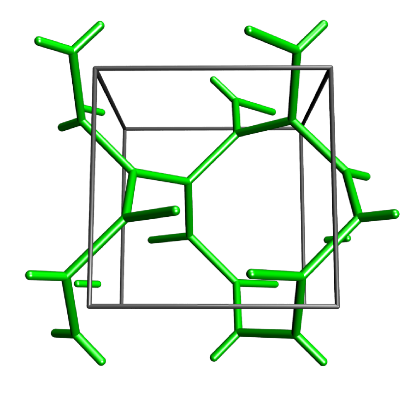
8-srs: cubic (211)
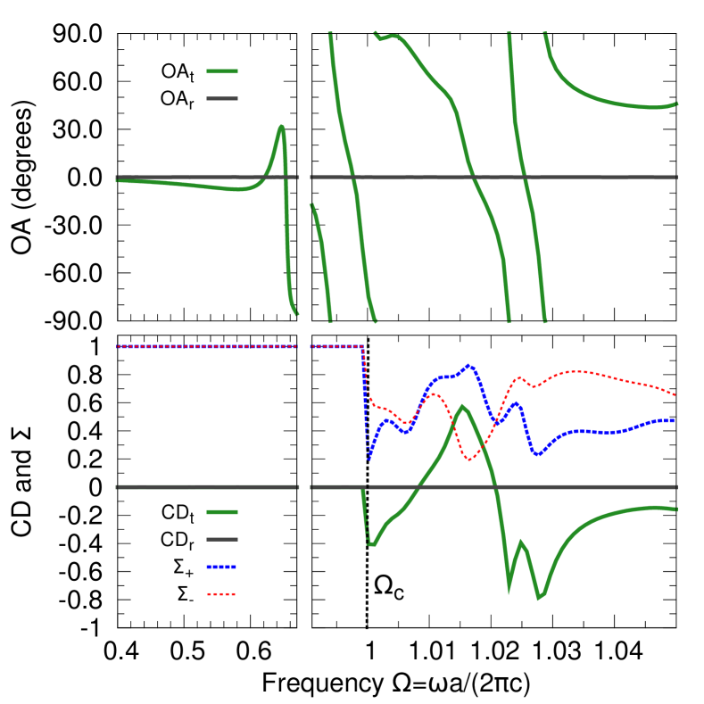
Circular birefringence or optical activity (OA) and circular dichroism (CD) are polarisation effects related to the chiral properties of a light-transmitting medium. In the literature, OA and CD correspond to the difference in the absorption coefficients and refractive indices between left- (LCP) and right-circularly polarized (RCP) light of a homogeneous non-transparent material Hecht (1998). Here, we adopt these terms for a slab of a lossless and inhomogeneous material, and relate OA and CD to the transmission and reflection amplitudes . We define OA as the phase difference and CD as the relative difference in absolute values between the complex scattering amplitudes or , respectively, for a respective incoming LCP () or RCP () plane wave:
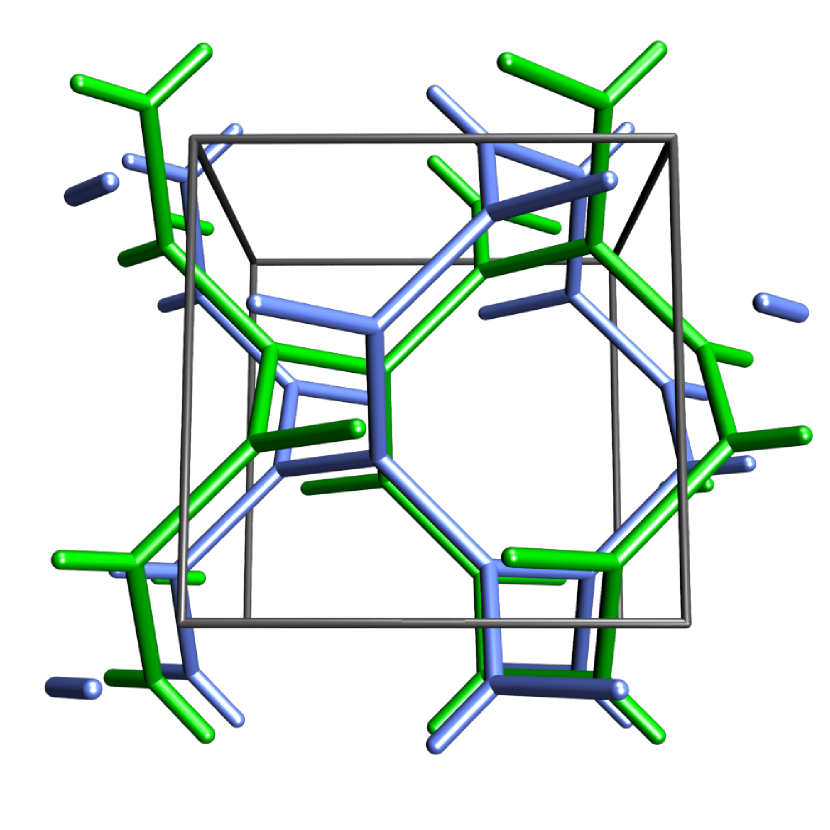
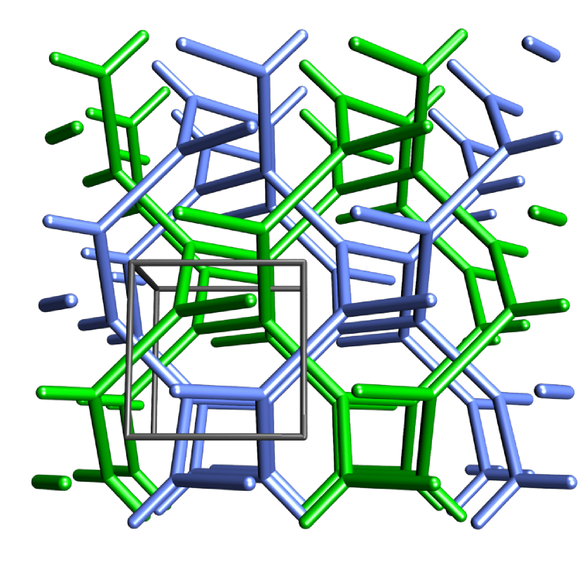
While theoretical conclusions of this article, based on group theory and scattering matrix treatment, are valid for any structure with symmetry (all nomenclature for symmetry groups as in Hahn (1992)), we use a particularly interesting geometry called 8-srs for illustration. The 8-srs is a periodic structure consisting of eight identical, and hence equal-handed, inter-threaded copies of the srs net Hyde and Ramsden (2000).
Figure 1 shows that the 8-srs is obtained by arranging translated copies of the srs net, such that all eight networks remain disjoint and to give body centered cubic symmetry 111See also the reticular chemistry structure resource www.rscr.anu.edu.au OKeeffePeskovRamsdenYaghi:2008 for details, where the 2-srs, the 4-srs and the 8-srs are denoted srs-c2*, srs-c4 and srs-c8, respectively.. With the lattice parameter of the 1-srs in its symmetry group , adding a copy translated by along gives the 2-srs of tetragonal symmetry; translation along a distinct coordinate axis by yields the 4-srs with simple cubic (SC) symmetry; translation by along the 8-srs with body-centered cubic (BCC) symmetry. Note that the 4-srs and the 8-srs have the same lattice constant . Importantly, the 8-srs has both four-fold rotation and four-fold screw axes along its [100] direction, see Fig. 2, in contrast to the 1-srs with only screw-rotations.
We consider the 8-srs as a dielectric PC obtained by inflating all edges of the 8-srs to solid struts (rods) with permittivity , embedded in vacuum. For the simulations, we use , close to high-refractive index Chalcogenide glass at telecommunication wavelengths Nicoletti et al. (2008) or at optical wavelengths Mille et al. (2013); the solid volume fraction is , corresponding to a rod diameter of . Finite size effects are obtained for a slab of size with inclination of the PC 222The infinite size in and direction is achieved by use of periodic boundary conditions assuming a single lateral unit cell of the 8-srs.. All analyses are for wave vectors along that axis and assuming termination planes perpendicular to . The parameter denotes the position of the termination plane in the unit cell.
Brillouin zone
By Bloch’s theorem, the translational symmetry, or periodicity, of a PC leads to a natural representation of the eigenmodes by a set of orthogonal basis modes, the Bloch modes. The Bloch wave vector characterises the translational symmetry behaviour of a mode and the band structure is the dependence of the frequency on .
In analogy to the translational symmetries, we now classify the behaviour of the eigenmodes under point symmetries (here rotational symmetries). Group and representation theory provides the formalism for this classification, in the form of irreducible representations , , and and their characters that uniquely define these, see Tab. 1. We analytically obtain the following general relationships valid for any PC with symmetry (including also the 8-srs, see Fig. 3):
(a) Three-fold degeneracy at the -point: The lowest eigenstates at the point are -fold degenerate. There are two and two modes defined in Tab. 1) and classified by their respective point symmetry behaviour 333The upper mode is out of frequency boundaries in Fig. 3..
(b) Degeneracy fully lifted on : The degeneracy is fully lifted when going away from the high symmetry points onto the line. Each mode split is summarized with a compatibility relation or (Tab. 1).
(c) Inversion symmetry and slope at and : Each band along is characterized by its irreducible representation . It has inversion symmetry and . The bands hence approach the points and with zero slope and the bands with equal and opposite slope.
Group theory combined with an analytic scattering matrix treatment yields the following four further general rules for photonic scattering at a finite slab of an PC, inclined at direction and hit by a plane wave at normal incidence (see Fig. 4 for simulations of the 8-srs). These include previous results Bai et al. (2007); Menzel et al. (2010); Kaschke et al. (2012) as special cases.
(d) correspond to non-interacting scattering channels, and represent RCP and LCP, respectively, A and B are dark modes: Modes of distinct representation do not interact. Scattering takes place in four independent channels characterized by the four representations . For each channel, a well-defined scattering matrix relating the amplitudes of the outgoing plane waves to those of the incoming plane waves is found. Both and representations represent dark modes that do not couple to any plane wave at normal incidence. At normal incidence, any mode couples only to RCP and any only to LCP plane waves. This implies that the channels corresponding to and do not contribute to the scattering process and there is no polarisation conversion between LCP and RCP in transmission and reflection at any wave length.
(e) No CD and OA in reflectance: The reflection matrices on both sides are identical for the (LCP) and the (RCP) channel. For the reflection spectrum, CD and OA are hence strictly zero for all wave lengths.
(f) No CD in transmission below a critical frequency : The matrix norm of the transmission matrices is identical for and channels. Henceforth, at low frequencies , where the portion of energy that leaves the crystal in the Bragg order is strictly , CD is zero. The matrix norm imposes no condition for circular dichroism above . Optical activity may be finite at any frequency.
The appendix outlines the proofs of the above claims. We now provide interpretations for the 8-srs PC:
Due to rules (d)-(f), an 8-srs slab of fixed thickness acts like an effective, optically active material for which the Kramers-Kronig relations are not valid; in contrast to homogeneous optically active materials, rotary power is not caused by a difference in the refractive indices for LCP and RCP but by the microstructure at the same length-scale as the wavelength of the light.
Rule (d) also provides an interpretation for our definition of OA and CD: If a linear polarised plane wave at normal incidence impinges on a finite slab, the perpendicularly scattered (zero Bragg order) wave is generally elliptically polarised. The principal axis of its polarisation ellipse is rotated by OA compared to the polarisation axis of the incoming wave and has eccentricity . For , the polarization plane is hence rotated without introducing any ellipticity.
All results are accurately reproduced by numerical calculations. Fig. 3 compares the transmission, which is the same for LCP and RCP light, through a thick slab with to the photonic band structure (PBS) of the infinite periodic PC. The PBS modes are colored according to their numerically determined irreducible representation Saba et al. (2013) and have a size proportional to the coupling constant Saba et al. (2011) that describes the ability of the Bloch mode to couple to an incident plane wave of the same frequency 444 has been slightly improved compared to Saba et al. (2011) by taking the field overlap integrals of the component vector instead of the three components of to take impedance mismatch between the coupled fields into account. is still only a rough estimate for transmission especially when several (partly evanescent) Bloch modes are involved in the scattering process.. The PBS shows the behaviour predicted by results (a)-(c): It is -fold degenerate at the point and splits into separate bands of irreducible representation (), and . The slopes near the point are consistent with result (c). The PBS is further in good agreement with the transmission spectrum. Notably, the transmission drop at the frequency is fully consistent with our band structure results: Since the band has a dark mode behaviour according to rule (d), the band structure exhibits a small pseudo-bandgap (with for , cf. teal points in Fig. 3) in the frequency range . Note that different choices of and give significantly larger bandgap width, see Fig. in Saba et al. (2013).
Fig. 4 shows OA and CD spectra. In agreement with (e), to any numerical precision. Consistent with (f), is only present above where the Bragg order is non-evanescent. is present at all frequencies and particularly strong above the fundamental bands with a large slope in the spectrum.
| TR | |||||
|---|---|---|---|---|---|
| (a) | |||||
| (a) | |||||
| (b) | |||||
| (b) |
Despite the absence of CD and ellipticity below , the rotation angle goes up to at even within the fundamental bands. This non-optimized PC exhibits therefore roughly of the optical rotation that can be achieved with metallic metamaterials Decker et al. (2010) operating at comparable wavelengths in the near-infrared. Transmission is almost at those wavelengths and dominated by a single mode process so that an effective medium approach is justified. The 8-srs operating in the upper fundamental band frequency region is hence a promising candidate for an optically active and lossless metamaterial.
In conclusion, the 8-srs is a prototype for a lossless chiral PC material that provides strong optical rotary power combined with zero ellipticity below a frequency threshold that is way above the fundamental band edges for reasonable dielectric contrast. This unique combination of desired chiro-optical behaviour makes it a good candidate for optical rotators or circular polarization beam splitters Turner et al. (2013). Further, the scattering process with a PC slab is highly non-linear so that optical activity changes rapidly at the frequencies where poles in the generalized Airy formula exist Byrne et al. (2006). It therefore also is an attractive metamaterial that could be used for optical switches which is fully scalable in contrast to e.g. liquid crystals in a smectic nematic phase.
Note that 1-srs and 2-srs PCs have been manufactured on the micron-scale with by direct laser writing (DLW) methods Turner et al. (2011, 2013). The DLW fabrication of the 8-srs appears therefore feasible at a structure size such that it exhibits all the basic features predicted by our theory in the near infrared.
While the 8-srs geometry is a particularly interesting design from a chiral-optical perspective, it is important to note that results (a-f) hold for any PC structure with symmetry . Even more generally, rules for the scattering matrix (d-f) are valid for any chiral PC with a -fold rotational symmetry in propagation direction.
Finally, we have restricted our representation analysis to the point of lowest vacuum frequency for the sake of simplicity. The reduction procedure, however, is equivalent for all higher or points with symmetry yielding for example the irreducible representations at and at . Furthermore, other directions or symmetries can be treated in the same way. Preliminary investigation for along (a -fold axis in general) yields the same main features as for on .
Acknowledgements.
We thank Stephen Hyde for the inspiration to analyse multiple inter-threaded network structures, and Nadav Gutman for pointing out the potential of group theory. We thank Michael Fischer for comments on the manuscript. MS, KM and GST acknowledge funding by the German Science Foundation through the Cluster of Excellence Engineering of Advanced Materials. MT and MG acknowledge funding by the Australian Research Council through the Centre for Ultrahigh-Bandwidth Devices for Optical Systems (project CE110001018).References
- Decker et al. (2007) M. Decker, M. W. Klein, M. Wegener, and S. Linden, Opt. Lett. 32, 856 (2007).
- Pendry (2004) J. Pendry, Science 306, 1353 (2004).
- Zhang et al. (2009) S. Zhang, Y.-S. Park, J. Li, X. Lu, W. Zhang, and X. Zhang, Phys. Rev. Lett. 102, 023901 (2009).
- (4) E. Plum, J. Zhou, J. Dong, V. A. Fedotov, T. Koschny, C. M. Soukoulis, and N. I. Zheludev, Phys. Rev. B 79, 035407.
- Liu et al. (2010) M. Liu, T. Zentgraf, Y. Liu, G. Bartal, and X. Zhang, Nat Nano 5, 570 (2010), 10.1038/nnano.2010.128.
- Michielsen and Stavenga (2008) K. Michielsen and D. Stavenga, J. R. Soc. Interface 5, 85 (2008).
- Saranathan et al. (2010) V. Saranathan, C. Osuji, S. Mochrie, H. Noh, S. Narayanan, A. Sandy, E. Dufresne, and R. Prum, PNAS 107, 11676 (2010).
- Schröder-Turk et al. (2011) G. Schröder-Turk, S. Wickham, H. Averdunk, M. Large, L. Poladian, F. Brink, J. Fitz Gerald, and S. T. Hyde, J. Struct. Biol. 174, 290 (2011).
- Hyde et al. (2008) S. T. Hyde, M. O’Keeffe, and D. M. Proserpio, Angew. Chem. Int. Ed. 47, 7996 (2008).
- Mille et al. (2013) C. Mille, E. C. Tyrode, and R. W. Corkery, RSC Adv. 3, 3109 (2013).
- Vignolini et al. (2011) S. Vignolini, N. A. Yufa, P. S. Cunha, S. Guldin, I. Rushkin, M. Stefik, K. Hur, U. Wiesner, J. J. Baumberg, and U. Steiner, Advanced Materials , n/a (2011).
- Turner et al. (2011) M. D. Turner, G. E. Schröder-Turk, and M. Gu, Optics Express 19, 10001 (2011).
- Lu et al. (2013) L. Lu, L. Fu, J. D. Joannopoulos, and M. Soljačić, Nature Photonics 7, 294 (2013).
- Turner et al. (2013) M. Turner, M. Saba, Q. Zhang, B. Cumming, G. Schröder-Turk, and M. Gu, Nature Photonics in press (2013).
- Hur et al. (2011) K. Hur, Y. Francescato, V. Giannini, S. A. Maier, R. G. Hennig, and U. Wiesner, Angew. Chem. Int. Edit. , n/a (2011).
- Saba et al. (2011) M. Saba, M. Thiel, M. Turner, S. T. Hyde, M. Gu, K. Grosse-Brauckmann, D. Neshev, K. Mecke, and G. E. Schröder-Turk, Phys. Rev. Lett. 106, 103902 (2011).
- Oh et al. (2013) S. S. Oh, A. Demetriadou, S. Wuestner, and O. Hess, Advanced Materials 25, 612 (2013).
- Hecht (1998) E. Hecht, Optics (Addison-Wesley, 1998).
- Hahn (1992) T. Hahn, ed., International Tables For Crystallography (Kluwer Academic Publishers, Dordrecht, 1992).
- Hyde and Ramsden (2000) S. T. Hyde and S. Ramsden, Europhys. Lett. 50, 135 (2000).
- Note (1) See also the reticular chemistry structure resource www.rscr.anu.edu.au OKeeffePeskovRamsdenYaghi:2008 for details, where the 2-srs, the 4-srs and the 8-srs are denoted srs-c2*, srs-c4 and srs-c8, respectively.
- Nicoletti et al. (2008) E. Nicoletti, G. Zhou, B. Jia, M. J. Venture, D. Bulla, B. Luther-Davies, and M. Gu, Opt. Lett. 33, 2311 (2008).
- Note (2) The infinite size in and direction is achieved by use of periodic boundary conditions assuming a single lateral unit cell of the 8-srs.
- Note (3) The upper mode is out of frequency boundaries in Fig. 3.
- Bai et al. (2007) B. Bai, Y. Svirko, J. Turunen, and T. Vallius, Phys. Rev. A 76, 023811 (2007).
- Menzel et al. (2010) C. Menzel, C. Rockstuhl, and F. Lederer, Phys. Rev. A 82, 053811 (2010).
- Kaschke et al. (2012) J. Kaschke, J. K. Gansel, and M. Wegener, Opt. Express 20, 26012 (2012).
- Saba et al. (2013) M. Saba, M. Turner, K. Mecke, M. Gu, and G. E. Schröder-Turk, submitted for review to Phys. Rev. B (2013).
- Note (4) has been slightly improved compared to Saba et al. (2011) by taking the field overlap integrals of the component vector instead of the three components of to take impedance mismatch between the coupled fields into account. is still only a rough estimate for transmission especially when several (partly evanescent) Bloch modes are involved in the scattering process.
- Decker et al. (2010) M. Decker, R. Zhao, C. M. Soukoulis, S. Linden, and M. Wegener, Opt. Lett. 35, 1593 (2010).
- Byrne et al. (2006) M. Byrne, L. Botton, A. Asatryan, N. Nicorovici, A. Norton, R. McPhedran, and C. M. de Sterke, OPE (2006).