New Concept for a Neutron Electric Dipole Moment Search using a Pulsed Beam
Abstract
A concept to search for a neutron electric dipole moment (nEDM) is presented, which employs a pulsed neutron beam instead of the nowadays established use of storable ultracold neutrons (UCN). The technique takes advantage of the high peak flux and the time structure of a next-generation pulsed spallation source like the planned European Spallation Source. It is demonstrated that the sensitivity for a nEDM can be improved by several orders of magnitude compared to the best beam experiments performed in the 1970’s and can compete with the sensitivity of UCN experiments.
pacs:
14.20.Dh, 13.40.Em, 11.30.Er, 07.55.Ge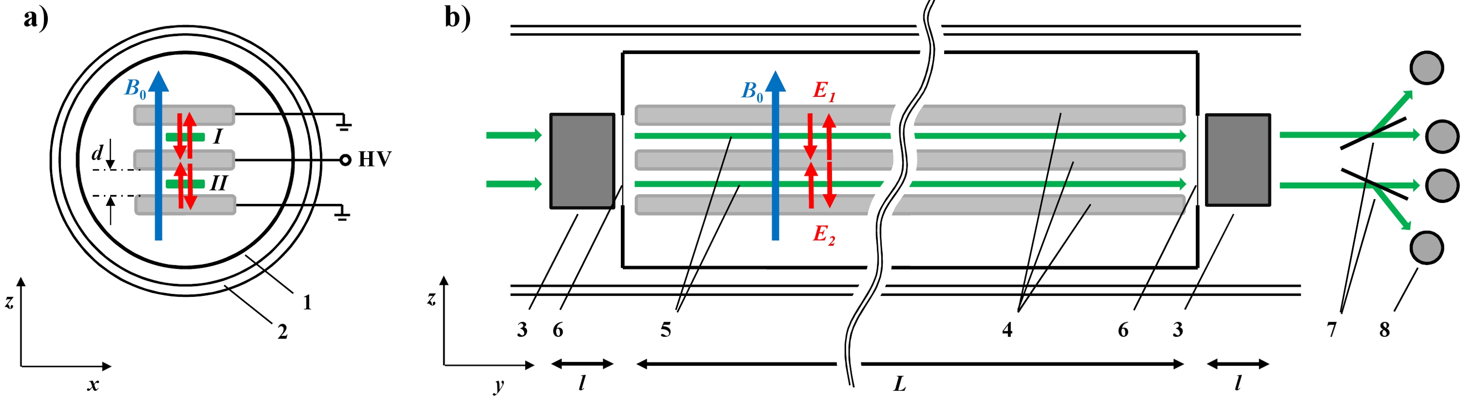
The search for electric dipole moments of fundamental particles and atoms presents a very promising route for finding new physics beyond the Standard Model of particle physics Raial/2008 ; Khriplovich/1997 . A permanent electric dipole moment violates parity (P) and time reversal symmetries (T) and, invoking the CPT theorem, also CP symmetry. However, new sources of CP violation are expected to be found in order to understand the observed large matter-antimatter asymmetry in the universe Sakharov/1967 ; Riotto/1999 ; Pospelov/2005 and because most extensions of the Standard Model allow for new CP violating phases.
Already in 1950, Purcell and Ramsey proposed a scheme to search for a non-vanishing neutron electric dipole moment (nEDM) Purcell/1950 .
An upper limit for is derived by comparing the neutron Larmor precession frequencies in a constant magnetic field superimposed with an electric field applied parallel and anti-parallel to , respectively. The difference in precession frequency is given by
| (1) |
where is Planck’s constant and is the magnetic moment of the neutron. In this formula the critical assumption is made that the magnetic field does not change during the course of the two measurements. Historically, the early nEDM experiments have been performed using neutron beams Smith/1957 ; Miller/1967 ; Baird/1969 ; Dress/1977 ; Ramsey/1986 , while current experiments and new projects prefer using ultracold neutrons (UCN) Baker/2006 ; Altarev/1996 ; Grinten/2009 ; Masuda/2012a ; Ito/2007 ; Altarev/2012 ; Baker/2011 ; Serebrov/2009b ; Lamoreaux/2009 .111A complementary approach to measure the nEDM using a neutron beam and crystal diffraction has so far reached a sensitivity of ecm Federov/2009 . Both methods employ Ramsey’s Nobel prize winning molecular beam method of separated oscillatory fields adapted to neutrons Ramsey/1949 ; Ramsey/1950 to measure the neutron spin precession phase . Here, is the interaction time of the neutron spin with the applied electric field. Experiments with UCN have the eminent advantage of much longer interaction times (in the order of s compared to about ms for neutron beam experiments), since UCN can be confined in so-called neutron bottles made of suitable materials with small loss cross sections Golub/1991 . This results in a largely improved sensitivity, since the statistical uncertainty (standard deviation) on the nEDM can be derived as
| (2) |
where is the total number of detected neutrons and the “visibility” of the Ramsey fringe pattern Golub/1972 . By contrast, much larger neutron count rates and up to times higher electric fields can be achieved in neutron beam experiments Baumann/1988 ; Dress/1977 ; Baker/2006 . The latter is possible because neutron beams do not require insulating wall material mounted between the high voltage electrodes as in experiments with stored UCN. However, the limiting systematic effect in beam experiments has so far been the relativistic -effect, which arises from the motion of the neutron through the electric field producing an effective magnetic field according to Maxwell’s equations, with being the speed of light in vacuum. In the most recent nEDM beam experiment this effect was corrected for by mounting the entire Ramsey spectrometer on a turntable, in order to reverse the direction of the neutron beam with respect to the apparatus Dress/1977 .
Stored UCN, however, have an average velocity of approximately zero and therefore the -effect is substantially reduced, seemingly rendering nEDM experiments with beams obsolete.
Lately, several sensitive Ramsey experiments using neutron beams have been performed vdBrandt/2009 ; Piegsa/2009a ; Piegsa/2008b ; Piegsa/2009b ; Piegsa/2011 ; Piegsa/2012a ; Piegsa/2012b , which revived the previously abandoned idea of a nEDM beam experiment.
Here, a concept is presented which overcomes the drawback and is able to reach sensitivities of UCN experiments. This is achieved by directly measuring the -effect
by employing a high intensity pulsed neutron beam. Such beams will be made available in the near future at the planned European Spallation Source (ESS) ESS/web or possibly at Fermilab’s Project X Projectx/web .
In Fig. 1 a scheme of the experimental setup of the proposed nEDM beam concept is presented. Two separated neutron beams ( and ) with a cross section of several cm2 and with the velocity directed along the -axis are initially polarized in direction. They are traveling inside a non-magnetic vacuum flight tube to avoid neutron scattering and absorption in air. Several layers of mu-metal provide shielding from the Earth’s magnetic field and other disturbing magnetic field sources. The beams are exposed to a static and homogeneous magnetic field and electric fields and applied along the -axis. In principle, the magnitude of can be chosen arbitrarily. For practical reasons and the suppression of systematic effects, however, a field of about T seems reasonable. The electric fields are established by means of three horizontally oriented parallel metallic electrodes (e.g. made from aluminum) with a total length m and a distance of some centimeters. The electrodes might be assembled from many well aligned short sections of m length. A horizontal electrode geometry is preferable, since neutrons of all velocities experience the same magnetic field, in contrast to a vertical arrangement where slow and fast neutrons will describe different flight parabola due to the gravitational interaction. Depending on the polarity of the high voltage applied to the middle electrode (the outer electrodes are connected to ground) the electric fields are oriented anti-parallel/parallel or parallel/anti-parallel with respect to . In order to avoid large losses due to beam divergence in direction the electrodes can be coated with a non-depolarizing supermirror multilayer structure, e.g. Cu/Ti or NiMo/Ti Padiyath/2004 ; Schanzer/2009 . Instead of metallic electrodes, one could alternatively employ neutron guide float glass utilizing the metallic supermirror coating as a thin conducting electrode layer. The Ramsey setup consists of two spin-flip coils which produce phase-locked oscillatory fields perpendicular to , e.g. longitudinal in direction. They are driven with a frequency close to the neutron Larmor precession frequency , where is the gyromagnetic ratio of the neutron. The amplitudes of the oscillatory fields need to be modulated in time and synchronized with the repetition rate of the spallation source, in order to produce optimal flips for neutrons of all velocities present in a neutron pulse Maruyama/2003 . Between the spin-flip coils, the neutron spins precess in the - plane perpendicular to the externally applied fields. The spins of the neutrons are analyzed by polarizing supermirrors which are transparent for one spin state and reflect the other and, thus, allow to separately detect both spins species.

The neutrons are detected as a function of time-of-flight in four detectors capable standing high count rates, compare e.g. Klein/2011 ; Gledenov/1994 . A so-called Ramsey pattern is obtained by measuring the count rate as a function of . One obtains Ramsey patterns for each beam and each time-of-flight bin, i.e. each neutron velocity. In Fig. 2 a simulated signal is presented. The distance between two neighboring fringe maxima is given by and the width of the envelope of the pattern is , where is the length of the spin-flip coils Piegsa/2008a .222Instead of performing a scan of the frequency, a similar Ramsey pattern is obtained by scanning the relative phase between the two oscillatory fields, which allows that the resonance condition is fulfilled permanently. Any additional precession of the neutron spins between the two spin-flip coils, for instance due to a nEDM, will cause a corresponding phase shift of the Ramsey fringes. The use of two beams allows to correct for phase drifts of the Ramsey patterns which equally appear in both beams (common noise rejection).
An aspect which needs to be taken into account, is dephasing of the neutron spins during precession. In order to avoid the accompanied loss in visibility of the Ramsey fringes, the lateral magnetic field gradients of averaged over the flight path need to be limited. The gradients should not exceed nT/cm, with cm and s. Such a field uniformity is achieved in the center of a Helmholtz coil with a radius of about cm. Hence, the field can be provided with a long pair of rectangular coils or a -coil with comparable dimensions.
Furthermore, magnetic field and field gradients should be constantly monitored with an array of sensors, e.g. fluxgates and atomic magnetometers Groeger/2006 ; Knowles/2009 ; Green/1998 ; Gemmel/2010 . An intriguing possibility would be to integrate a co-propagating beam of polarized 3He atoms as a magnetometer/gradiometer () Eckel/2012 ; DeKieviet/1995 . Alternatively, two additional neutron beams, which are not exposed to the electric fields, traveling below and above the two nEDM beams would serve the same purpose.
The described Ramsey setup represents a very sensitive apparatus to measure small magnetic and pseudomagnetic fields very accurately by determining the phase shifts of the Ramsey fringes. A nEDM interacting with an electric field can be described by the pseudomagnetic field . Inserting the present best upper limit ecm (90% C.L.) Baker/2006 and an electric field of MV/m yields a corresponding field fT. The magnitude of a magnetic field due to the -effect for neutrons with a velocity of m/s in the same electric field is many orders of magnitude larger nT. Firstly, however, in a nEDM experiment is oriented perpendicular to the main field and thus leads only to a small correction
and secondly, it is proportional to the neutron velocity. Hence, by employing a pulsed neutron beam and measuring Ramsey patterns for different velocities the effect on the neutron spins caused by and can be well separated.
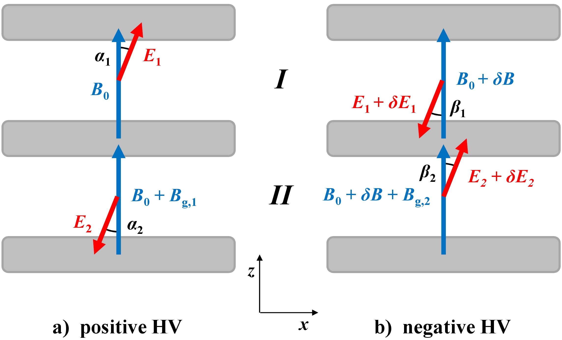
The electric and magnetic fields experienced by the neutron beams and are depicted in Fig. 3.
A nEDM is determined by two Ramsey measurements with different electric field settings, here achieved by applying either a positive or negative high voltage to the middle electrode. In this generalized scheme also a non-perfect alignment of the fields, field instabilities and magnetic field gradients are taken into account. The effective magnetic fields for a positive voltage are given by
| (6) | |||||
| (10) |
And for a negative applied voltage
| (14) | |||||
| (18) |
where the magnetic fields and represent magnetic field gradients in direction. In Eq. (6) - (18), we have assumed small tilting angles and for , negligible changes of the electric field magnitudes after polarity reversals, i.e. , and , to approximate the pseudomagnetic fields due to the nEDM in all cases by . Magnetic fields in direction are neglected since the only case where they become relevant, namely a geometric phase, is treated later. Further, by taking into account that the magnetic field change between the two measurements, , and are all much smaller than , one derives the frequency shift
| (19) | |||||
| (20) |
using that and with describing the change in the magnetic field gradient. and , with . Hence, the velocity dependent phase shift
| (21) |
can be divided into three parts. The first part containing the pseudomagnetic nEDM effect and is proportional to , while the first and second order terms of the -effect are constant and proportional to , respectively. If the second order term is sufficiently suppressed, a value or upper limit for the nEDM can be extracted by plotting as a function of and determining the slope by a linear fit.
In the following, the statistical sensitivity of the proposed concept is compared to experiments using UCN. Since the uncertainty on given in Eq. (2) scales with , the length of the spin precession region should be as large as possible. In the neutron-antineutron oscillation experiment performed at the research reactor of the Institut Laue-Langevin (ILL) in Grenoble, an approximately m long neutron flight tube shielded with mu-metal was employed Baldo/1994 ; Bitter/1991 . Assuming a similar setup with m and neutrons with an average velocity of 500 m/s yields s. Thus, a gain factor can be expected, since precession times of about 100 s can be routinely achieved in UCN experiments. Due to the higher electric fields reachable in beam experiments, about MV/m instead of MV/m, a gain factor is obtained.
The neutron count rate in the latest UCN experiment was approximately s-1, as an average of UCN were detected per s long measurement cycle Baker/2006 .
At the planned spallation source ESS the time averaged flux will be equivalent to the continuous flux at the ILL reactor with an unpolarized neutron capture flux-density comparable to the one available at the fundamental physics beam line PF1b of about cm-2s-1 Peggs/2012 ; Abele/2006 .
The ESS will produce pulses of approximately ms length with a repetition rate of about Hz. Hence, assuming a total source-to-detector distance of m, allows for neutron velocities e.g. between m/s and m/s, i.e. a neutron de Broglie wavelength band from nm to nm. This band can be selected most efficiently with only small losses, by using neutron optical devices installed upstream of the experimental setup. For instance by means of a frame overlap filter to scatter out neutrons with longer wavelengths and a curved neutron guide to avoid transmission of neutrons with a wavelength shorter than nm.
Integrating the differential flux-density given in Ref. Abele/2006 over this wavelength range yields a neutron particle flux-density of cm-2s-1. Thus, employing a polarizing cavity with an average transmission of %, a polarized neutron particle flux-density of about cm-2s-1 is deduced Aswal/2008 ; SwissN/web .
Together with an estimated correction of or for divergence losses in two dimensions (with absorbing electrodes) or one dimension (with supermirror coated electrodes), respectively, one can expect a neutron count rate at the detector between cm-2s-1 and cm-2s-1.
These values are consistent with the measured unpolarized neutron flux of about cm-2s-1 after almost 100 m free propagation given in Ref. Baldo/1994 and calculations using flux brightness data from Ref. Abele/2006 .
This leads to a gain factor of for two neutron beams with a cross section of 20 cm2 each (e.g. cm2).
Ultimately, one can further improve the sensitivity by at least a factor , by means of a neutron optical system with parabolic/elliptic guides focusing on the cold moderator Schanzer/2004 . In total, this results in a sensitivity gain compared to the present best UCN experiment Baker/2006 and with respect to the best beam experiment Dress/1977 . Inserting the values for optimized conditions into Eq. (2) yields a nEDM sensitivity ecm, i.e. a magnetic field sensitivity fT, assuming days of data taking and . This matches the precision envisaged
by future UCN experiments Grinten/2009 ; Masuda/2012a ; Ito/2007 ; Altarev/2012 ; Baker/2011 .
Finally, possible systematic effects are considered which could disguise a real or produce a false nEDM signal. As already mentioned, the second order term in Eq. (21) has to be smaller than the statistical sensitivity per day, i.e. fT, since the high voltage polarity will be reversed only a few times in 24 hours. This is achieved by a relative precision of the inverted fields and alignment accuracies e.g. � and �, assuming m/s, MV/m and T. The electric field precision can be assured by monitoring the high voltage and providing a corresponding mechanical stability. The angular alignment can be tested by applying an additional magnetic field in direction and minimizing the phase shift due to the first order -effect. The main systematic effect is due to changing magnetic field gradients. Random fluctuations need to be monitored by means of gradiometers with a precision better than the statistical sensitivity of the neutron measurement. Gradients which are correlated with the orientation of the electric field, e.g. a magnetization of the mu-metal shield generated while reversing the high voltage polarity, have to be smaller than fT to achieve the final sensitivity goal. However, a false nEDM signal originating from is inversely proportional to the electric field and can therefore be reduced up to a factor compared to nEDM searches with UCN. Another effect occurs, if there exist a net neutron velocity in and an electric field component in direction. This causes an effective -field along the -axis. The field is well suppressed, if e.g. mm/s and the inclination angle between the electric and magnetic fields in direction is smaller than � (with MV/m). An upper limit for the effect is obtained by intentionally increasing the inclination (add magnetic field in direction) or/and (shift beam apertures in direction). Further, a geometric phase arises when a magnetic field component in direction exists with different values and at the entrance and exit of the electric field Commins/1991 . This yields in the adiabatic limit the phase
| (22) |
which has to be added to Eq. (21), where and . The effect is, however, distinguishable from a nEDM signal by inverting the direction of the main magnetic field, if is caused by the coils producing .
An upper limit for which does not reverse with inverting the magnetic field can be determined by measuring at lower Abdullah/1999 ; Commins/1994 .
Moreover, a false signal caused by the geometric phase is suppressed below ecm, if nT, assuming the aforementioned values for , , and .
In conclusion, a nEDM beam experiment has been reconsidered. A new concept exploits the advantage offered by a pulsed spallation source, to directly measure the so far limiting systematic -effect. The method is well superior to previous beam experiments and has the potential to significantly improve the present best measurement of the nEDM obtained with UCN. A statistical sensitivity of ecm can be achieved in days of data taking.
The author gratefully acknowledges many useful discussions with Klaus Kirch, Peter Böni, Ben van den Brandt, Martin Fertl, Stefan Filipp, Patrick Hautle, Michael Jentschel, Jochen Krempel, Guillaume Pignol, Christian Schanzer, Torsten Soldner and Oliver Zimmer.
References
- (1) M. Raidal et al., Eur. Phys. J. C 57, 13 (2008).
- (2) I.B. Khriplovich and S.K. Lamoreaux, CP-violation without strangeness (Springer, Berlin, 1997).
- (3) A. Riotto and M. Trodden, Ann. Rev. Nucl. Sci. 49, 35 (1999).
- (4) A.D. Sakharov, JETP Lett. 5, 24 (1967).
- (5) M. Pospelov and A. Ritz, Annals Phys. 318, 119 (2005).
- (6) E.M. Purcell and N.F. Ramsey, Phys. Rev. 78, 807 (1950).
- (7) J.H. Smith, E.M. Purcell, and N.F. Ramsey, Phys. Rev. 108, 120 (1957).
- (8) P.D. Miller, W.B. Dress, J.K. Baird, and N.F. Ramsey, Phys. Rev. Lett. 19, 381 (1967).
- (9) J.K. Baird, P.D. Miller, W.B. Dress and N.F. Ramsey, Phys. Rev. 179, 1285 (1969).
- (10) W.B. Dress et al., Phys. Rev. D 15, 9 (1977).
- (11) N.F. Ramsey, Physica B 137, 223 (1986).
- (12) C.A. Baker et al., Phys. Rev. Lett 97, 131801 (2006).
- (13) I.S. Altarev et al., Phys. At. Nucl. 59, 1152 (1996).
- (14) M.G.D. van der Grinten, Nucl. Instr. Meth. A 611, 129 (2009).
- (15) Y. Masuda, K. Asahi, K. Hatanaka et al., Phys. Lett. A 376, 1347 (2012).
- (16) T.M. Ito, J. Phys. Conf. Ser. 69, 012037 (2007).
- (17) I. Altarev et al., Il Nuovo Cimento 35 C, 122 (2012).
- (18) C. Baker, G. Ban, K. Bodek et al., Physics Procedia 17, 159 (2011).
- (19) A.P. Serebrov et al., Nucl. Instr. Meth. A 611, 263 (2009).
- (20) S.K. Lamoreaux and R. Golub, J. Phys. G: Nucl. Part. Phys. 36, 104002 (2009).
- (21) V.V. Federov et al., Nucl. Instr. and Meth. A 611, 124 (2009).
- (22) N.F. Ramsey, Phys. Rev. 76, 996 (1949).
- (23) N.F. Ramsey, Phys. Rev. 78, 695 (1950).
- (24) R. Golub, D.J. Richardson, S.K. Lamoreaux, Ultra-Cold Neutrons (Taylor & Francis, New York, 1991).
- (25) R. Golub and J.M. Pendlebury, Contemp. Phys. 13, 519 (1972).
- (26) J. Baumann, R. Gähler, J. Kalus, and W. Mampe, Phys. Rev. D 37, 3107 (1988).
- (27) B. van den Brandt et al., Nucl. Instr. and Meth. A 611, 231 (2009).
- (28) F.M. Piegsa, B. van den Brandt, P. Hautle, J. Kohlbrecher, and J.A. Konter, Phys. Rev. Lett. 102, 145501 (2009).
- (29) F.M. Piegsa, B. van den Brandt, P. Hautle, and J.A. Konter, Nucl. Instr. and Meth. A 586, 15 (2008).
- (30) F.M. Piegsa, B. van den Brandt, P. Hautle, and J.A. Konter, Nucl. Instr. and Meth. A 605, 5 (2009).
- (31) F.M. Piegsa, B. van den Brandt, P. Hautle, and J.A. Konter, Physica B 406, 2409 (2011).
- (32) F.M. Piegsa and G. Pignol, Phys. Rev. Lett. 108, 181801 (2012).
- (33) F.M. Piegsa and G. Pignol, J. Phys. Conf. Ser. 340, 012043 (2012).
- (34) The European Spallation Source, http://www.esss.se/.
- (35) Project X at Fermilab, http://projectx.fnal.gov/index.shtml.
- (36) J. Padiyath, J. Stahn, P. Allenspach, M. Horisberger, and P. Böni, Physica B 350, e237 (2004).
- (37) C. Schanzer, P. Böni, and M. Schneider, J. Phys. Conf. Ser. 251, 012082 (2009).
- (38) R. Maruyama et al., Physica B 335, 238 (2003).
- (39) M. Klein, C.J. Schmidt, Nucl. Instr. and Meth. A 628, 9 (2011).
- (40) Yu.M. Gledenov et al., Nucl. Instr. and Meth. A 350, 517 (1994).
- (41) F.M. Piegsa et al., Nucl. Instr. and Meth. A 589, 318 (2008).
- (42) S. Groeger et al., Sensor. Actuat. A 129, 1 (2006).
- (43) P. Knowles et al., Nucl. Instr. and Meth. A 611, 306 (2009).
- (44) K. Green et al., Nucl. Instr. and Meth. A 404, 381 (1998).
- (45) C. Gemmel et al., Eur. Phys. J. D 57, 303 (2010).
- (46) S. Eckel, S.K. Lamoreaux, M.E. Hayden, and T.M. Ito, Phys. Rev. A 85, 032124 (2012).
- (47) M. DeKieviet, D. Dubbers, C. Schmidt, D. Scholz, and U. Spinola, Phys. Rev. Lett. 75, 1919 (1995).
- (48) M. Baldo-Ceolin et al., Z. Phys. C 63, 409 (1994).
- (49) T. Bitter et al., Nucl. Instr. and Meth. A 309, 521 (1991).
- (50) H. Abele et al., Nucl. Instr. and Meth. A 562, 407 (2006).
- (51) ESS Technical Design Report, edited by S. Peggs (2012).
- (52) V.K. Aswal et al., Nucl. Instr. and Meth. A 586, 86 (2008).
- (53) SwissNeutronics AG, http://www.swissneutronics.ch/.
- (54) C. Schanzer, P. Böni, U. Filges, and T. Hils, Nucl. Instr. and Meth. A 529, 63 (2004).
- (55) E.D. Commins, Am. J. Phys. 59, 1077 (1991).
- (56) K. Abdullah, C. Carlberg, E.D. Commins, H. Gould, and S.B. Ross, Phys. Rev. Lett. 65, 2347 (1990).
- (57) E.D. Commins, S.B. Ross, D. DeMille, and B.C. Regan, Phys. Rev. A 50, 2960 (1994).