A current driven electromagnetic
mode in sheared and toroidal configurations
István Pusztai1,2, Peter J Catto1,
Felix I Parra1,3, Michael Barnes1,41 Plasma Science and Fusion Center, Massachusetts
Institute of Technology, Cambridge, MA 02139, USA
2
Department of Applied Physics, Chalmers University of Technology and
Euratom-VR Association, SE-41296 Göteborg, Sweden
3
Department of Physics, University of Oxford, Oxford, OX1 3PU, UK
4 Department of Physics, University of Texas at Austin,
Austin, TX 78712, USA
pusztai@chalmers.se
Abstract
The induced electric field in a tokamak drives a parallel electron
current flow. In an inhomogeneous, finite beta plasma, when this
electron flow is comparable to the ion thermal speed, the Alfvén
mode wave solutions of the electromagnetic gyrokinetic equation can
become nearly purely growing kink modes. Using the new ”low-flow”
version of the gyrokinetic code gs2 developed for momentum
transport studies [Barnes et al 2013 Phys. Rev. Lett.111
055005], we are able to model the effect of the induced parallel
electric field on the electron distribution to study the destabilizing
influence of current on stability. We identify high mode number kink
modes in gs2 simulations and make comparisons to analytical
theory in sheared magnetic geometry. We demonstrate reassuring
agreement with analytical results both in terms of parametric
dependences of mode frequencies and growth rates, and regarding the
radial mode structure.
1 Introduction
The radial gradient of electric current represents a source of free
energy in fusion plasmas which can drive or modify instabilities. For
a sufficiently strong current gradient, kink modes can be
destabilized. The criterion for destabilization in a screw pinch was
derived in [1] with a magnetohydrodynamic formulation
(there referred to as the screw-instability) for high mode numbers.
Low mode number kink modes are important for the internal stability of
tokamaks. The internal kink mode is believed to be responsible
for the sawtooth instability [2]. Most of the work done on
these modes uses a fluid formalism. However, accounting for kinetic
effects is important to reproduce all details of the evolution of such
instabilities. For instance, finite electron inertia can assist
collisionless reconnection that can modify the dynamics of
internal kinks, as well as their coupling to ion sound waves, as
discussed in [3]. In addition, considering fluid ions and
kinetic electrons, collisional and diamagnetic effects on the
mode were studied in [4]. In spite of the recognized
importance of kinetic effects on kink modes, at present there are only
a limited number of numerical studies in the literature which employ
gyrokinetic [5, 6] simulations. The first is a
simulation of a sawtooth crash that was reported in [7],
where a particle-in-cell (PIC) code neglecting ion finite Larmor
radius (FLR) effects was used to model the instability for straight
field lines. More recently, ideal-MHD internal kink and collisionless
tearing mode simulations were performed in a screw pinch
geometry in [8] with the PIC code gygles
[9]. Gyrokinetic studies on modifications to kinetic
instabilities due to parallel current are also very limited. In
[10] the effects of equilibrium current on reversed shear
Alfvén eigenmodes is studied using the PIC code gtc
[11]. Moreover, the continuum gyrokinetic code gene
[12] is used in [13] to study magnetic reconnection,
where alternating current sheets are modeled in a periodic slab
configuration. Linear gyrokinetic simulations of tearing modes in the
collisional–-collisionless transitional regime in a slab geometry are
presented in [14] using the AstroGK code
[15]. These last two references introduce the parallel current
as a first-order gyrokinetic perturbation, rather than an unperturbed
drive term (part of the background distribution) as we do in this
article.
It is of interest to further develop our kinetic simulation capability
for current driven instabilities. Using the tools available in the new
version of the gyrokinetic code gs2 [16], developed for
intrinsic rotation studies in tokamaks [17], we are now
able to model the destabilizing effect of the modifications to the
non-fluctuating electron distribution function due to an induced
electric field in a tokamak. In particular, current driven modes can
be studied using this continuum gyrokinetic code, as demonstrated
herein through simulations of high mode number kink modes with gs2. The gs2 simulations presented here are radially
local (flux tube), which inherently assumes a separation of the
parallel and perpendicular scale lengths of perturbed
quantities. Accordingly, in gs2, only high mode number modes
can be simulated, while global modes, such as the mode are
beyond the region of applicability of local codes. The simulations
are done in toroidal geometry and no simplifying assumptions (i.e.,
regarding finite Larmor radius effects, kinetic treatment of
different species, particle drifts etc.) are made to the
Maxwell-gyrokinetic system apart from those consistent with the
lowest order local gyrokinetic treatment. The new feature is the
treatment of the modification to the electron distribution due to
the induced electric field as an unperturbed drive term entering as
a part of the non-fluctuating distribution. The code results will
be shown to be in very good agreement with the analytical calculations
we present.
The subsequent sections are organized as follows. First, in
Sec. 2 the electromagnetic gyrokinetic equations are derived
in toroidal geometry in the presence of an induced parallel electron
current. In Sec. 3, the dispersion relation of the high
mode number kink modes is derived in shearless toroidal geometry. The
effects of magnetic shear and the eigenmode structure are discussed in
Sec. 4. Finally, in Sec. 5 the analytical
results are compared to gs2 simulations, before we conclude in
Sec. 6.
2 Electromagnetic gyrokinetic equations with induced current
The induced electric field driven part of the non-fluctuating electron
distribution is similar to the solution of the Spitzer problem,
, where is the
linearized electron collision operator, is the Maxwell distribution, with
the density , temperature , mass and charge of
species (ions and electrons are denoted with the indices and
, respectively). Furthermore, denotes the induced parallel
electric field, and , with the
velocity and the unit vector in the direction of the equilibrium
magnetic field . The Spitzer function is proportional to
, but it may have a non-trivial speed dependence. However, as it
will be shown later through simulations, the exact velocity space
structure of is unimportant for the instability to be
investigated here. Therefore, the induced electric field effects will
be modeled simply by allowing for a parallel drift velocity.
To derive the linearized gyrokinetic equation it is convenient to use
the unperturbed total energy, , the
magnetic moment, , and the canonical
angular momentum as phase-space
variables. Here, , , is
the non-fluctuating part of the electrostatic potential, denotes
the speed of light, is the major radius, is the
poloidal magnetic flux, and , with the toroidal
angle and . The unperturbed Vlasov operator
acting on functions of only and vanishes in a toroidally
symmetric system which we shall consider. We have introduced , with . The time independent
piece of the distribution functions should be close to
(1)
where , and the pseudo-density is
with
and . Note that , and are
assumed to be flux functions. We consider . By
construction, reduces to a Maxwellian as .
In order to account for the electron flow due to the induced electric
field, we model the non-fluctuating electron distribution by
(2)
where ,
is the particle guiding center,
and is the particle position. Furthermore, , and the parallel electron flow velocity is , where is
allowed to be comparable to the ion thermal speed
, and the sign of is chosen so that the unperturbed
current density is . For the electron flow to be divergence
free, .
The linearized kinetic equation for the fluctuating part of the
electron distribution can be written as
(3)
where collisions are neglected since we are interested in the
tokamak core, where the collision frequency is small. The
fluctuating parts of the electric and magnetic fields are denoted by
and ,respectively. We note, that the induced
electric field is accounted for by retaining its effect on
the non-fluctuating distribution, i.e. keeping in . The
induced electric field is negligible in the term of
(3), since electron-ion drag requires it to be the same
order as a collisional correction.
We represent the perturbed vector potential as
, and work in the Coulomb gauge
(). Using we obtain
(4)
where we define . At this point we may
neglect finite orbit width corrections to the kinetic equation by
replacing by and by
.
The preceding analysis for is essentially exact, however, we
simplify the analytic treatment for by considering large aspect
ratio tokamak magnetic geometry with low
normalized pressure , where is the
minor radius and is the ion pressure. We assume that the
gyrokinetic ordering is satisfied by any perturbed quantity ,
namely , , and
, where represents the
perpendicular scale length of background plasma
parameters. Additionally, we assume the and the
parts of to be
comparable in magnitude.
Next we consider acting on . Neglecting the
term and the poloidal variation of as small in , gives
(5)
where and we use
. We introduce the
thermodynamic forces and , where we denote
-derivatives by ′. Using
we find
(6)
Defining
(7)
and, combining (3), (4) and (6), we derive
the kinetic equation governing this portion of the distribution
function
(8)
To obtain this equation we made use of the fact that vanishes
when acting on and , and thus it
approximately vanishes when acting on and ,
as finite orbit width effects are neglected. Furthermore, we used
.
Following a procedure similar to that in [5] we can
derive the gyro-kinetic equation. After a transformation to gyro
center variables, a gyro-phase average of the kinetic equation
(8) is performed and finite orbit width effects are neglected
where appropriate. We neglect compressional magnetic perturbations as
small in the normalized pressure . For electrons we also neglect FLR
corrections. We note that vanishes upon
gyro-phase averaging and the term in the last line
of (8) is small in the gyrokinetic ordering and therefore can
be neglected. We arrive at the result
(9)
where the electron drift velocity of the guiding center in the
equilibrium magnetic field is , and the parallel component
of the fluctuating vector potential is
. This form of follows from
assuming straight field line coordinates,
i.e. with a flux function. The full
fluctuating electron distribution and are related
by
(10)
where a term
has been neglected as small in our ordering. The magnitude of this
term will be quantified in the beginning of Sec. 3 when a
specific form for the perturbations will be assumed.
We keep FLR corrections when deriving the ion gyrokinetic equation to
obtain the usual result
(11)
where denotes a gyro-phase average at fixed
guiding center position, and the relation between and is
given by
(12)
where again, a term has been neglected for our
ordering.
So far we have derived the linearized electromagnetic gyrokinetic
equations, where we allow for a parallel flow of electrons. We assumed
large aspect ratio and small beta, and neglected and electron
FLR effects, but otherwise the equations (9-12) are
still rather general. In the next section we shall derive a dispersion
relation for the high mode number kink modes, where further
approximations regarding the magnetic geometry and the mode structure
will be made.
3 Dispersion relation of the high mode number kink mode
In this section we assume a flute like mode structure for the
perturbed quantities ,
where the fluctuations are elongated along magnetic field lines with
, where is the safety factor. From
we find and thus
and
with the parallel
wave number. The size of is set by
assuming . We consider a pure plasma, but allow the
ion charge number to be different from 1. By assuming to be
comparable with the minor radius of the device, we can neglect
magnetic drifts as small in as compared to the diamagnetic
drifts when deriving our dispersion relation. The justification of
neglecting magnetic drifts, which is a good approximation at long
wavelengths, will be further discussed towards the end of this
section. Finally, the mode frequency is assumed to be
comparable or larger than the diamagnetic frequency . We find that the terms
neglected in the derivation of (10) and (12) are
smaller than the terms by , with the ion
gyro radius.
From quasineutrality we have
(13)
where for electrons and ions are given in (10)
and (12). The velocity integrals of the parts of
the distributions are straightforward to evaluate. Using
quasineutrality for the unperturbed densities, equation (13)
reduces to
(14)
where denotes the ion charge number. The fluctuating
parallel current is given by
(15)
Again, the velocity integrals of can be readily evaluated
using the relations (10) and (12), to find
(16)
Note that the velocity integrals of (13-16) are taken
at fixed particle position, while the appearing in the
gyrokinetic equations are functions of the guiding center position.
When the magnetic drifts are neglected the gyrokinetic equations are
of the form
(17)
where represents the right hand sides of (9)
and (11) for and , respectively. We integrate
(17) over the velocity space at fixed particle position and
sum over species to find
(18)
The velocity integrals are to be performed in and variables,
and the Jacobian is , leading to the form of the second term of
(18). For electrons the integral of gives
(19)
For ions we need to account for FLR effects. We use to evaluate the integral for the ions through
first order in , where is the
perpendicular wave number. As a result we find
(20)
We then substitute (14), (16), (19) and
(20) into (18) and use quasineutrality to find
(21)
Realizing that the term on the left hand side of
(21) together with the term on the right hand
side of (21) exactly cancel with the term, we can
simplify to obtain
(22)
where we employ the mode structure and define . Introducing the
background current gradient and the pressure gradient driven diamagnetic
frequencies
Then we employ the parallel Ampère’s law
, and recall , where is
the Alfvén speed, to rewrite the left hand side of (24)
as . We focus on the
limit, that is . This approximation will be justified at the end of this
section. We use this relation to eliminate from (24)
in favor of , and then divide by to
obtain the dispersion relation
(25)
The solution of (25) for the mode frequency is then
(26)
This result is consistent with Equation (15) of [18], which
was derived in a shearless slab geometry. In the limit (26) reduces to
(27)
For a given wave number if the electron flow speed or the
normalized pressure is sufficiently small the first term
dominates on the right hand side of (27), and the solution is
an Alfvén wave with purely real frequency . However, for high enough , and the second term might exceed the first and, depending on the
relative sign of and u, (27) describes either a pair
of stable modes with purely real frequencies or a purely growing and a
purely damped mode.
For the rest of this section we will be concerned with the purely
growing mode driven by the current gradient. Clearly, decreasing the
perpendicular wave number of the mode increases the growth rate of the
mode. Since the first term in (27) is quadratic and the
second term is linear in , there is an optimal value of the
parallel wave number, , where the mode has the highest
growth rate, . When the plasma parameters and the perpendicular
wave number are fixed the optimum is
(28)
and the growth rate corresponding to is
(29)
When and , the
assumption used to obtain
(27) is satisfied if . As
long as there is a finite plasma beta and electron current, one can always
find sufficiently small perpendicular wave number for which this
relation is satisfied in the limit. In this
case, neglecting magnetic drifts in the gyrokinetic equation is also
justified as long as the pressure length scale is much smaller than
the major radius.
It is shown at the end of A, the perturbed quasineutrality
equation can be written in the form , where is a dimensionless function of order unity
(as long as is not too large) and is small
in . Thus, neglecting the small correction from , the
approximate quasineutrality equation is satisfied either if , or , that is if , which we assumed in deriving
(27). The case includes drift wave solutions and the
strongly damped modes corresponding to electrostatic roots of the
uniform plasma dispersion relation in the presence of electron flow.
4 Magnetic shear effects
To obtain simple analytical results in Section 3 we
neglected magnetic drifts and assumed a flute like mode structure
(with no radial variation). The mode tends to be more unstable at low
perpendicular wave numbers, thus it is appropriate to neglect the
magnetic drifts, .
Due to the preceding assumptions, the result (26) is
formally the same as what one would obtain solving the problem in a
shearless slab geometry [18]. The only difference between
a torus and a slab is that and
have lower limits set by the lowest finite
toroidal wave number . We note that in a shearless slab there is
no such periodicity constraint, and can get arbitrarily
small (thus arbitrarily large) for sufficiently large
perpendicular wave lengths. This unphysical behavior is partly
resolved by taking finite magnetic shear into account, which is needed
for the magnetic geometry to be consistent with a substantial parallel
current. In this section we will study the consequences of a magnetic
shear in slab geometry.
We choose a coordinate system such that plasma
parameters vary in the direction, and consider a mode which is
sinusoidally varying in the direction with a corresponding wave
number , while the magnetic field has the form . The magnetic shear produces an variation in ,
namely , and we choose the origin so that
. We assume that the radial variations of the perturbed
quantities are faster than those of the unperturbed ones and
, thus the component of the electron flow can be
neglected () together with any change in the
magnitude of .
To obtain a dispersion relation in a sheared geometry we start with
(24) and insert parallel Ampére’s law together with
to find
(30)
Then, we assume to replace in (30)
by , which is consistent with neglecting
terms in the quasineutrality equation. Taking
the -derivative of (30) leads to the dispersion
relation in terms of the -component of the perturbed magnetic field,
(31)
where is defined by . The dispersion relation is essentially the same as in shearless
geometry, except for the linear -dependence of , and that the
replacement cannot be made.
Recalling and introducing the dimensionless
“radial” coordinate , (31) can be rewritten in the
form
(32)
where and
. The boundary conditions for this eigenvalue problem in
are given by the requirement that . In (32) represents the drive
and corresponds to
an instability . During the analysis of the radial
eigenmodes we shall neglect
corrections, and refer to the solutions as unstable and
the solutions as marginally stable modes. We will retain
corrections in Section 5. We note
that reversing the sign of , that is, the relative sign of
and , leads to the same eigenvalues, and the corresponding
eigenfunctions satisfy . Thus,
henceforth we will analyze solutions corresponding to ,
without loss of generality.
For small values of , (32) is dominated by the
term, that is solved by . Accordingly,
the solutions are either linear or quadratic in around . For
high values of the first term dominates (32), leading to
the an exponential asymptotic behavior ,
consistent with the boundary conditions. To solve numerically we
rewrite the eigenvalue problem (32) for as
(33)
and discretize it using a second order finite difference scheme. We
set as the negative , and for the
positive , boundary conditions to select solutions with the appropriate
asymptotic behavior. Then we numerically search for the eigenvalues
and eigenfunctions of the system for a given .
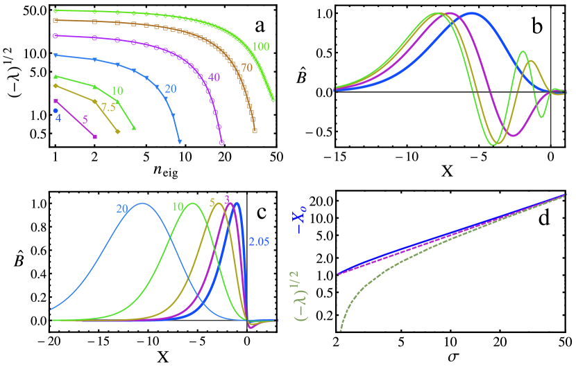
Figure 1: Solutions of the eigenvalue problem (32). (a)
Normalized growth rates of unstable modes
corresponding to .
The number of unstable modes increases with
. (b) Radial eigenmodes of the four unstable mode at
. Lower growth rates correspond to more oscillatory
structure. (c) The most unstable radial eigenmodes for
. The distance of the location of the maximum
of , from increases with . (d) Solid curve:
, where is the location of the maximum of for
the most unstable mode at a given value of . Dash-dotted
curve: normalized growth rate of the most
unstable mode. Dashed curve: .
Figure 1 shows solutions of the eigenvalue problem
(32). We find that as the drive is increased, more and
more unstable eigenfunctions appear, as illustrated in Figure
1a showing the normalized growth rates of
all the unstable eigenmodes for different values of . On the
x-axis of Figure 1a, denotes the ordinal number of
the unstable modes, with corresponding to the most
unstable mode for each value of . In fact, a new unstable mode
appears as exceeds for every positive integer . In
particular, no unstable mode exists for . Note that in
Figure 1 the marginally stable () modes for even
values of are not shown.
For , the marginally stable () solutions of
(32) are of the form for and
for . Here, denotes the Kummer confluent
hypergeometric function, and is a polynomial with only
positive coefficients (, , ,
…). The derivative of the marginally stable solutions is
discontinuous at , however it is resolved by a boundary layer at
for with an arbitrarily small and a
corresponding small eigenvalue . The boundary layer connects
the solution vanishing at , to a solution
for , which is
finite at . Here, (for real values of ) denotes the Exponential integral,
where indicates that the principal value is to be used
for . No marginally stable solution to (32) exists if
, since in this case becomes divergent at ,
and the boundary condition cannot be
met.
When more than a single unstable eigenmode exists (), the
ones with lower growth rates exhibit a more oscillatory radial
structure, as illustrated in 1b showing the four unstable
modes for . In particular, the most unstable mode
(corresponding to the thickest curve in 1b) does not change
sign in the region , while all the other unstable modes do. This
is consistent with the behavior of the marginally stable modes, since
for increasing the number of roots of increases.
The amplitude of the most unstable eigenmode has a maximum
close to the radial location where would maximize the local
dispersion relation (27), that is
with the optimal wave number given in
(28).
In terms of , the location of scales as
according to the local theory. As shown in
1d, the location of the maximum amplitude (solid curve,
representing ) follows this expectation (dashed curve,
) quite well. In the strongly driven () limit
the normalized growth rate of the most stable
eigenmode (dash-dotted curve in 1d) approaches the optimal
value, given by (29). This value corresponds to
. However, gives
(that is, no unstable mode) in the sheared slab
model, while the local theory would predict a finite growth rate
equivalent with .
In conclusion, considering magnetic shear sets a stability limit in
terms of the drive at in contrast to the shearless model
that predicts instability when , the current gradient and the
flow speed are finite. In the shearless case the mode is always
allowed to pick the optimal parallel wave number.
The stability criterion of the mode is equivalent to that
of the high mode number kink modes. Using the relations ,
, , and , with the
poloidal mode number, together with the definitions of and
, one can rewrite the stability criterion
as
(34)
as obtained from the magnetohydrodynamic energy principle in
[1] – see Equation (2.29) therein.
5 Mode characteristics in toroidal geometry
In this section the high mode number kink mode investigated in
Sections 3 and 4 is studied numerically
using the gyrokinetic code gs2. gs2 is free from the
simplifying assumptions made in Section 4, except for the
radial locality and the scale separation . In the
low-flow version of gs2 extra terms related to neoclassical
corrections to the non-fluctuating part of the distribution function
and the electrostatic potential are implemented for momentum transport
studies, as discussed in [17]. These quantities are
specified as inputs, normally calculated by the neoclassical code neo [19]. This infrastructure can in principle be used to include any
modification to the non-fluctuating part of the distribution over a
velocity range of a few thermal speeds. We use it to include , as
defined after (2), or more sophisticated Spitzer functions,
to study the effect of the induced electric field on
instabilities. Normally, we include only a parallel flow in gs2
simulations, instead of a full Spitzer function since the results are
insensitive to the detailed form.
First we consider the parametric dependences of the mode frequency and
the growth rate, and compare gs2 simulations to predictions of the
sheared slab model (SSM) (31). The SSM results are obtained
by choosing the most unstable eigenmode from the numerical solution of
(33). We use a 200 point radial grid, the extent of which is
adapted to the expected width of the eigenfunctions depending on the
value of .
The scans are performed about the following set of base-line
parameters: , , ,
, , , ,
, and , where , ,
, and . We set the
density and temperature gradients to zero to avoid the appearance of
the usual gradient driven modes (otherwise, for this ,
magnetic shear and kinetic ballooning modes appear
and pollute the results, as in [20]). Then the only instability
drive is due to the gradient of the flow speed. The radial gradient of
the flow speed in the Ohmic current is due to density and electron
temperature gradients, thus our settings are not physically
consistent. However, by artificially choosing the parameters we obtain
a cleaner comparison between theory and simulations.
The binormal wave number and the aspect ratio are chosen to be small
so that magnetic drifts are not expected to affect the results
significantly. For a typical gs2 simulation only an extended
poloidal angle range of is kept and
grid points along the field line are used, since the eigenfunctions of
strongly driven modes are highly oscillatory and very localized in
. The simulations use 20 untrapped pitch angle- and 14 energy
grid points. We neglect collisions and compressional magnetic
perturbations.
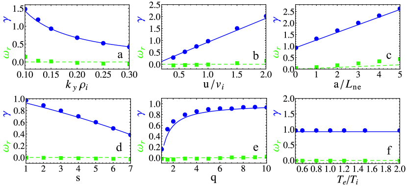
Figure 2: Parametric scalings of the growth rate (solid line
and circle markers) and real frequency (dashed lines and
square markers) of the high mode number kink mode (given in
units). Markers represent gs2 simulations and lines are
results of the sheared slab model. The figures depict the dependence
on the following: (a) binormal wave number , (b) electron
flow velocity , (c) density gradient , (d) magnetic
shear , (e) safety factor , and (f) temperature ratio
.
Figure 2 shows various parameter scalings around the
baseline parameter set. In a strongly driven situation (), the growth rate is expected to be close to (29),
which helps in interpreting the numerical results. Since , and , we expect a dependence
of the growth rate, which is observed in Fig. 2a. Magnetic
drifts should be more important towards higher wave numbers. The good
agreement remains between gs2 and the SSM even at
due to the very large aspect ratio . The
growth rate is expected to increase linearly with the flow speed and
the mode should be stable at and this behavior is seen in
Fig. 2b. Similarly, the growth rate should exhibit the
linear dependence on as shown, where the mode is unstable at
due to the finite gradient in the flow speed, see
Fig. 2c.
To translate magnetic geometry parameters from the toroidal geometry
of gs2 to a sheared slab we use . Although the local
model can be used to explain certain parametric dependences of the
mode, it cannot provide predictions for the dependence. However
we know that as drops below due to a
decreasing , the mode should be completely stabilized. Thus we
expect increasing should reduce the growth rates, as seen in
Fig. 2d. Clearly, should have the opposite effect as
, since . Indeed, Fig. 2e shows
that the mode is stabilized with decreasing . Also, when the mode
is strongly driven, , the growth rate should become
independent of , since the mode approaches the local
result. Hence, there is a saturation in the -dependence of
towards higher values of . When and are
held fixed the growth rate given in (29) normalized to
is independent of . The insensitivity of the result
to the temperature ratio is demonstrated in Fig. 2d.
The real part of the frequency is proportional to the ion
diamagnetic frequency , which should be zero in
almost all the scalings of Fig. 2, since the ion pressure
gradient is zero. The only exception is the density gradient scaling,
Fig. 2c, where should increase linearly with
. Although, we find the right trend ,
gs2 produces higher values than the slab model. The reason for
this discrepancy is likely that the mode is not purely kink anymore,
but instead develops some kinetic ballooning character due to the finite
pressure gradient drive.
There are small deviations from the result of the slab
model in the gs2 simulations in Fig. 2a, b and
d-f. These may be the result of the magnetic drift effects neglected in the
slab model, but also, they may also represent the finite accuracy of the
simulations. In certain cases, when is very
high, making the parallel mode structure very oscillatory,
exceptionally high parallel resolutions were necessary in gs2 to
achieve the accuracy presented in Fig. 2 (for example 140
grid points in ).
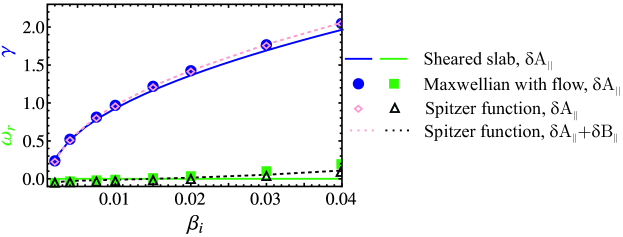
Figure 3: scaling of the growth rate (upper
curves and points) and real frequency of the high mode
number kink mode (given in units). The solid lines are
sheared slab model results, the dotted curves and symbols are gs2 simulation results computed using a shifted Maxwellian
electron distribution (full symbols), using a Spitzer function
keeping only fluctuations (empty symbols), and using a
Spitzer function keeping both and fluctuations
(dotted curves).
The expected dependence of the growth rate of
the high mode number kink modes is reproduced, as seen in
Fig. 3. Apart from the sheared slab results (solid)
lines, Fig. 3 shows gs2 simulations of different
levels of sophistication. In the simplest case the non-fluctuating
electron distribution is modeled as a Maxwellian with a finite
parallel flow velocity (shown with solid symbols). It is interesting
to see that when the shifted Maxwellian is replaced by a Spitzer
function with the same flow speed but considerably more complicated
velocity space structure (given by (B4) and (B8) of [21]), the
results (empty symbols) remain practically unchanged, especially for
the growth rates. Spot checks for different plasma parameters show
the same behavior. This demonstrates that the velocity structure of
the non-fluctuating part of the electron distribution is
unimportant, and that only its parallel flow speed matters for the
kink mode. All the simulations presented herein include
only perturbations except those shown with the dotted lines in
Fig. 3. We find that in the strongly driven cases
corresponding to our baseline set of parameters, compressional
magnetic perturbations have no significant impact on the mode
frequencies.
We note that the normalized ideal magnetohydrodynamic drive,
often referred to as the MHD inertial-layer width
[8] is qualitatively different for the high-m kink
modes studied here and for the mode [22]. This
drive, which determines the ideal MHD growth rate of the mode, is
small in the case (as compared to )
making the near marginally stable mode sensitive to non-ideal
effects such as collisional or collisionless reconnection. Although
the simulations shown in Figs. 2 and 3 are
collisionless and they do not resolve scales of the electron skin
depth, these high-m modes are so strongly unstable due to the ideal
MHD drive that they are not expected to be sensitive to physics
happening in small layers around the surface.
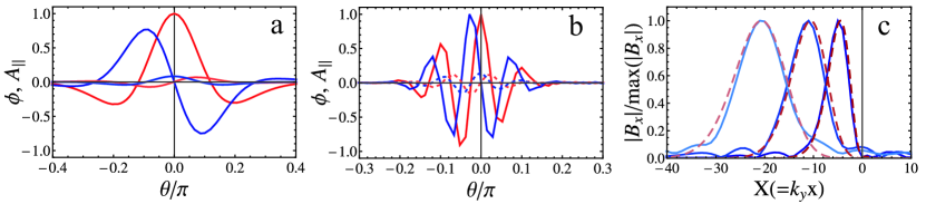
Figure 4: a-b: Parallel mode structures from gs2
simulations. Solid curves are , and dashed curves are ;
red and blue curves correspond to the real and imaginary parts,
respectively; and (a) , (b) . (c) The
radial mode structures in the SSM (dashed curves) and calculated
from gs2 parallel mode structures (solid curves);
, the corresponding curves peak at
increasing values.
Typical parallel mode structures are shown in Figures
4a and b. These simulations are done for the baseline
parameters with varying plasma beta; and in
4a and b, respectively. Note that the kink drive,
, is still finite due to the finite density
gradient. Increasing , corresponds to more oscillatory
parallel structures (larger ), as expected from
(28), and an increasing amplitude of the magnetic
component of the fluctuations. In the sheared slab geometry, the
parallel wave number increases away from the resonant surface (recall
).
The Fourier transform of the sheared slab problem in the
coordinate can lead to an equation that is equivalent to the problem
in ballooning representation with a coordinate along the magnetic
field line [23]. More precisely, the radial eigenfunction in
the sheared slab, , is related to the ballooning
eigenfunction, , by . Figure
4c shows that the kink modes considered here have this
same property. It compares the variation of the radial mode structure
[the magnitude of ] in sheared slab calculations (dashed
lines), with the transform of the ballooning mode variation obtained
from gs2 (solid), for different values of . The solid
line peaking the closest to (and furthest away from) the rational
surface correspond to the ballooning eigenfunction in
Fig. 4a (and b, respectively). The “ballooning
character” of the eigenfunctions, that is, their localization
around , is simply a consequence of how a mode with a
finite radial extent appears in ballooning representation, rather
than a result of a poloidal dependence in the drive of the mode. In
particular it is not a magnetic drift effect. As the radial extent
of increases with increasing , the equivalent
becomes more and more localized around
according to the properties of the Fourier transformation.
We note that from the
sheared slab dispersion relation (30) and the long wavelength ballooning equations solved by gs2 can be recovered using the replacements
and .
6 Discussion and conclusions
We have developed a procedure for modeling current gradient driven
kink instabilities in a tokamak with gs2 gyrokinetic simulations
and compared the results to the analytical expressions we derived.
We find that at sufficiently high current gradient high mode number
kink modes are destabilized. The properties of strongly driven kink
modes can be understood from simple analytical expressions derived in a
shearless magnetic geometry by assuming that the mode chooses an
optimal, finite parallel wave number that maximizes its growth
rate. In terms of kinetic quantities, the mode is destabilized by high
, strong parallel electron flow , high values of
, and small perpendicular wave numbers.
Since the mode is more unstable for smaller values of the
perpendicular wave numbers , magnetic drift effects
() are unimportant for describing the
stability of the mode. A perhaps more important effect of toroidicity
is that there is a lower limit on set by the lowest finite
toroidal mode number . However, both the analytical calculations
and gs2 assume a scale separation and disregard
global profile and magnetic geometry variations, thus are unable to
properly treat low mode number magnetohydrodynamic modes. Therefore
the stability limit, which we derive based on kinetic theory,
coincides with the magnetohydrodynamic stability limit for high mode
number kink modes [1]. In the sheared slab magnetic
geometry we find that the mode is strongly asymmetric, being localized
on one side with respect to a resonant () surface. The
parallel wave number corresponding to the radial location of the
highest amplitude is close to the one that maximizes the growth rate
in the local theory. The number of unstable radial eigenmodes
increases with increasing drive.
We find good agreement between gs2 simulations and analytical
estimates both in terms of the parametric dependences of the growth
rates and mode frequencies, and in terms of eigenmode
structure. The large aspect ratio and small limit of
high mode number kink modes may be used as a simple test case for
linear validation of electromagnetic gyrokinetic codes when current
drive is to be modeled. By comparing kink modes assuming a
Maxwellian electron distribution with a parallel flow and
alternatively a Spitzer function departure from a Maxwellian as a
drive we demonstrate that the exact velocity structure of the
non-fluctuating electron distribution function is unimportant for the
mode. Only the parallel flow speed of electrons matters.
For modes that are electrostatic in nature, an electron flow – even
when comparable to the ion thermal speed – is not expected to
significantly modify their stability. The circulating electrons which
can flow along the field lines are close to be adiabatic, and their
already small non-adiabatic response is only modified by an even
smaller correction from the flow. Without showing specific gs2
results, we remark that we have found practically no effect on ion-
and electron temperature gradient modes for typical plasma parameters
even when the plasma and the electron flow speed exceeds their
experimentally relevant range in the simulations.
In a screw-pinch geometry it is known that, if an ideal
magnetohydrodynamic mode is unstable at a given finite poloidal mode
number , it should be even more unstable at all mode numbers
satisfying [24]. Therefore, the trend of
increasing growth rate with decreasing is not terminated
until the lowest wave number allowed in the system. Consequently, if
the plasma is globally stable to low mode number kink modes, it should
be stable for all mode numbers. However, since a similar theorem has
not been proven in toroidal geometry, the relevance of high mode
number kink modes in tokamaks is unclear, and should be the subject of
future investigations. Toward this end, the research herein
demonstrates that suitably modified gyrokinetic codes can be used to
investigate current driven or kink instabilities in
tokamaks. A local code such as gs2 permits the
modeling of only high wave number modes, but it has the important
advantage that it can effectively model the nonlinear evolution of
these modes, which is a topic for future studies.
The authors are thankful to Jesus Ramos, Jack Connor, Jeff
Freidberg, and Jim Hastie for several fruitful discussions on MHD
related problems, and to Choongki Sung for providing experimental
parameters. This work was funded by the European Communities under
Association Contract between EURATOM and Vetenskapsrådet (VR), and
by the US Department of Energy grant at DE-FG02-91ER-54109 at MIT. The
first author is grateful for the financial support of VR.
Appendix A Quasineutrality
To derive the explicit form of the quasineutrality equation from
(14) we write it as
(35)
where the integrals are taken at fixed particle position. First we
will evaluate the electron contribution to quasineutrality, i.e. the
first two terms of (35). We neglect the magnetic drifts in
(9), replace time derivatives by , toroidal
derivatives by , write , and then
divide the equation by , to obtain
(36)
The integral in (35) can be directly
evaluated in terms of the plasma dispersion function, using that
(37)
where the integration is done along the Landau contour.
After a straightforward calculation we find that the
electron contribution to the dispersion relation is
(38)
where we introduced , the normalized flow
speed , the diamagnetic frequency , and .
Once the ion magnetic drifts are neglected, the gyro-averages
are replaced by , and the
-derivatives are written in terms of , from
(11) can be easily expressed as the familiar form
(39)
When we evaluate the velocity integral for ions in (35) we
expand in the FLR parameter, writing
, where we recall the definition
. The ion contribution to the dispersion
relation, normalized to , is obtained to be
(40)
Note that (38) and (40) contain the
contributions from the adiabatic responses. When the perturbed
quasineutrality equation (35) is formed the contributions from
and [the last terms in
(38) and (40), respectively] cancel for a
pure plasma, due to quasineutrality and .
Due to the high electron thermal speed is typically small. As
long as is not much larger than unity there are
terms multiplying in the electron
contribution to quasineutrality (38). In the ion
contribution (40), the terms in the last line, which
cannot be factorized by are multiplied by
that is assumed to be small in our expressions. In conclusion, the
quasineutrality equation has an order unity part that can be
factorized by , and the rest is small in
. This means that to satisfy quasineutrality, either
and should nearly cancel or the
coefficient factorized by should be close
to zero.
References
References
[1] Kadomtsev B B and Pogutse O P 1970 Rev. Plasma Phys. Vol5 249, ed. Leontovich M A.
[2] Kadomtsev B B 1975 Sov. J. Plasma Phys.1 389.
[3] Basu B and Coppi C 1981 Phys. Fluids24
465.
[4] Drake J F 1978 Phys. Fluids21 1777.
[5] Catto P J 1978 Plasma Phys.20 719.
[6] Frieman E A and Chen L 1982 Phys. Fluids25 502.
[7] Naitou H, Tsuda K, Lee W W and Sydora R D 1995 Phys. Plasmas2, 4257.
[8] Mishchenko A and Zocco A 2012 Phys. Plasmas19, 122104.
[9] Mishchenko A, Könies A and Hatzky R 2009 Phys. Plasmas16 082105.
[10] Deng W, Lin Z and Holod I 2012 Nucl. Fusion52 023005.
[11] Lin Z, Hahm T S, Lee W W, Tang W M and White R B
1998 Science281 №5384, 1835.