also ]BNL also ]Portland Physics Institute
One 4-Twist Helix Snake to Maintain Polarization in 8-120 GeV Proton Rings
Abstract
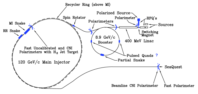
Solenoid Siberian snakes have successfully maintained polarization in particle rings below 1 GeV, but never in multi-GeV rings because the Lorentz contraction of a solenoid’s would require impractically long high-field solenoids. High energy rings, such as Brookhaven’s 255 GeV Relativistic Heavy Ion Collider (RHIC), use only odd multiples of pairs of transverse B-field Siberian snakes directly opposite each other. When it became impractical to use a pair of Siberian Snakes in Fermilab’s 120 GeV Main Injector (see Fig. 2), we searched for a new type of single Siberian snake, which should overcome all depolarizing resonances in the 8.9–120 GeV range. We found that one snake made of one 4-twist helix and 2 short dipoles could maintain the polarization. This snake design might also be used at other rings, such as Japan’s 30 GeV J-PARC, the 12–24 GeV NICA proton-deuteron collider at JINR-Dubna, and perhaps RHIC’s injector, the 25 GeV AGS.
pacs:
29.27.Bd, 29.27.Hj, 41.75.AkTo study the strong interaction’s spin dependence with polarized proton beams dgcrabb ; spin00 ; spin02 ; spin04 ; spin06 ; spin08 , one must preserve and control the polarization during acceleration and storage This can be difficult due to many depolarizing (spin) resonances. In 1977 Derbenev and Kondratenko Derbenev:1977 proposed a clever way to overcome all depolarizing resonances with arrangements of magnets now called Siberian snakes. Each snake rotates each beam particle’s spin by 180∘. This idea was first publicized in the West by Courant courant who coined the name Siberian snake. The concept was first tested at the Indiana University Cyclotron Facility (IUCF) Cooler ring in 1989 adk using a single longitudinal solenoid snake, which is very efficient at 100 MeV energies, but inefficient above a few GeV. In a ring with one snake, the protons’ stable spin direction is in the horizontal plane; and it is longitudinal exactly opposite the snake. In a ring with snake pairs exactly opposite each other, the stable spin direction is vertical. The Derbenev and Kondratenko papers Derbenev:1977 ; Derbenev:1978 noted that for transverse magnetic fields the seen by protons is almost invariant under the Lorentz transformation above a few GeV. This is because the needed for a 180∘ spin rotation only increases like the velocity, .
More recently two other facilities have used solenoid Siberian snakes to achieve polarized electron beams, the Amsterdam Pulse Stretcher Amps and MIT’s Bates South Hall Ring mit . Others commissioned studies of how to accelerate and maintain polarized proton beams including, SSC ssc , Fermilab’s Tevatron fermi , and DESY’s HERA Alekseeva:1996tt . Moreover, Brookhaven has fabricated and used two helical 4 T Siberian snakes in each RHIC ring to successfully accelerate, store and collide 100–255 GeV polarized protons Alekseev:2003sk .
.
In flat horizontal rings, a beam proton’s spin precesses around the ring dipole magnets’ vertical fields. The spin tune is the number of spin precessions during one turn around the ring, where is a proton’s Lorentz energy factor and is its gyromagnetic anomaly. Horizontal magnetic fields can perturb the proton’s stable polarization creating depolarizing spin resonances stora ; khoe ; montague ; khiari ; sylee , which occur whenever
| (1) |
where , and are integers; and are the horizontal and vertical betatron tunes, respectively. Imperfection spin resonances occur when . Intrinsic spin resonances occur when either or , or both; the sum defines each resonance’s order.
A proper snake must rotate the vertical spin component by exactly (180∘). It must also be optically transparent, which means that, to the rest of the ring, it appears to be an empty space. Moreover, the excursions caused by the snake must fit well inside the beam’s vacuum chamber. To make a helical snake optically transparent requires a pair of short dipoles with opposite vertical B-fields upstream and downstream of the helix.
At Fermilab’s 120 GeV Main Injector (see Fig. 2), the beam excursions caused by a single helix were too large at its 8.9 GeV injection energy. Thus, we studied the properties of a multi-twist helix, which was first discussed by Kondratenko kondra82 and then studied in detail by Courant courant88 , who considered only helical snakes with twist angles of , etc. To obtain optical transparency, these need both a horizontal and a vertical dipole at each end. Thus, we focused on multi-twist snakes that need only one vertical dipole at each end, with twist angles of , ; and finally chose .
A 1-twist helical dipole’s magnetic field is given by
| (2) |
where the coordinates are: (radial), (vertical) and (longitudinal); while , and is the helix’s length. The magnetic fields, the protons’ resulting excursions and spin behavior in the 4-twist helix were obtained by treating it as four 1-twist helices in series. The beam excursions were obtained by inserting into the tracking program the Lorentz force,
| (3) |
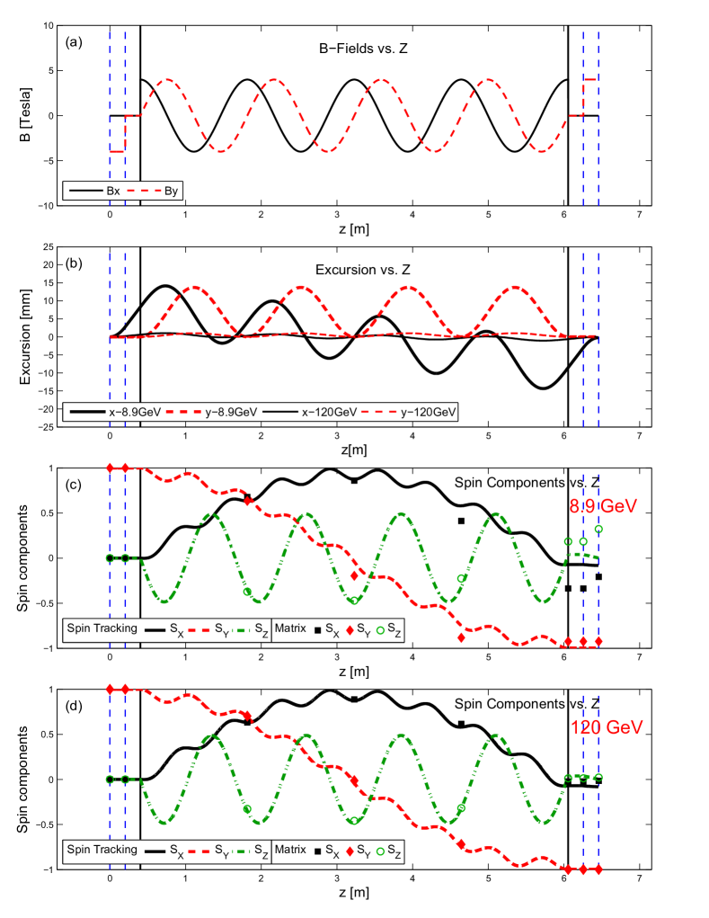
Numeric spin tracking calculations were made using the magnetic fields from Eq. (2) in 780,000 steps along the snake’s 6.459 m length. At each point along the snake axis, the change in spin was calculated using the Thomas-BMT equation lht ; bmt ,
| (4) |
The resulting spin components are shown in Fig. 1, along with the magnetic field components and the horizontal and vertical excursions.
Due to concern that fringe fields might reduce the polarization, spin tracking calculations were also performed assuming a fringe field which drops linearly from 4 T at 1,2,3,4 or 5 cm inside to 2 T at each edge of each magnet and to 0 T at 1,2,3,4 or 5 cm past each edge. As shown in Table I, these unrealistically large changes in the fringe field were found to have no effect on the precisely 180∘ spin flip of the vertical spin component; they did have small effects on the radial and longitudinal components, but a snake’s ability to maintain a stable polarization at the point opposite the snake is affected only by its ability to flip the vertical polarization by 180∘.
Analytic excursion calculations were also done using the equation for a 1-twist helix obtained by Courant courant96
| (5) |
where . The spin calculations were done using the matrix obtained by Syphers syp and a new matrix for linearly changing fields. Each 1-twist helical dipole rotates the spin by angle around the helix’s spin rotation axis according to
| (6) |
where , and where the magnetic rigidity, () is the ratio of a proton’s momentum to its charge. The matrix for the 4-twist helix was obtained by multiplying four 1-twist helices in series.
Note that, in going from a 1-twist to 4-twist helix, the maximum transverse excursions inside the helical snake decrease almost 4-fold (from 4.76 mm to 1.26 mm at 120 GeV and 64.18 mm to 16.55 mm at 8.9 GeV), while the total snake length increases by only 29% (from 4.242 m to 5.459 m).
These analytic matrix calculations were done for fringe fields from the dipoles but no fringe fields from the 4-twist helix, since we found a matrix for the dipole fringe fields by taking the derivative of Eq. 4 and solving the resulting linear differential equation, but we were unable to find a matrix for the 4-twist helix’s fringe fields. For the 180∘ vertical spin flip these matrix calculations are consistent with the corresponding spin tracking calculations which includes both dipole and helix fringe fields at the level at 120 GeV and deviate at the 0.06 level at 8.9 GeV, as shown in Fig. 1 and Table I. It also shows that the spin tracking calculations are independent of the fringe field length at the level at 120 GeV and at the level at 8.9 GeV. Moreover, all 5 analytic matrix calculations are independent of the dipole fringe field length, (confirmed by these calculations at the level at both 120 GeV and 8.9 GeV). Thus, the effect of any fringe fields should be negligible.
We found that by changing the beam energy by a few GeV from the nominal 120 GeV, the polarization direction at the end of the beam-line can be rotated within the horizontal plane or into the vertical direction as required by the Fermilab E-1027, the Polarized Drell-Yan experiment Drell-Yan exp . This is at the end of a 2.4 km beam with 140 bending magnets, some with horizonal magnetic fields, some with vertical fields and others with skew fields.
| 8.9 GeV | X spin | Y spin component | Z spin | |||
|---|---|---|---|---|---|---|
| Fringe | M | T | Matrix | Track | M | T |
| 0 (cm) | -0.208 | -0.080 | -0.9234 | -0.9967 | 0.3223 | 0.00083 |
| cm | -0.208 | -0.081 | -0.9234 | -0.9967 | 0.3223 | 0.00085 |
| cm | -0.208 | -0.081 | -0.9234 | -0.9967 | 0.3223 | 0.00096 |
| cm | -0.208 | -0.081 | -0.9234 | -0.9967 | 0.3223 | 0.00101 |
| cm | -0.208 | -0.080 | -0.9234 | -0.9968 | 0.3223 | 0.00137 |
| cm | -0.208 | -0.080 | -0.9234 | -0.9968 | 0.3223 | 0.00164 |
| 120 GeV | X spin | Y spin component | Z spin | |||
|---|---|---|---|---|---|---|
| Fringe | M | T | Matrix | Track | M | T |
| 0 cm | -0.018 | -0.0004 | -0.9995 | -1.000 | 0.0254 | 0.00000 |
| cm | -0.018 | -0.0004 | -0.9995 | -1.000 | 0.0254 | 0.00000 |
| cm | -0.018 | -0.0004 | -0.9995 | -1.000 | 0.0254 | 0.00000 |
| cm | -0.018 | -0.0002 | -0.9995 | -1.000 | 0.0254 | 0.00000 |
| cm | -0.018 | -0.0000 | -0.9995 | -1.000 | 0.0254 | -0.00001 |
| cm | -0.018 | 0.0004 | -0.9995 | -1.000 | 0.0254 | -0.00003 |
In summary, by using two independent spin calculation techniques, we showed that one can flip the vertical spin component by very near (180∘) by using a new type of single Siberian snake with transverse magnetic fields. This should maintain the polarization for proton beams in the Fermilab Main Injector up to 120 GeV. This single snake containing a 5.653 m, 4-twist, 4 T single helical dipole, with a 0.203 m, 4 T dipole on either end should maintain the proton polarization in the Fermilab Main Injector up to 120 GeV. Such a transverse field 4-twist single-snake configuration opens new possibilities for polarized proton beams in rings where it is difficult to place pairs of snakes at points 180∘ apart.
We thank I. Korbanis and H. B. White Jr. for their advice on Fermilab’s evolving Main Injector. We thank the University of Michigan for supporting this work.
References
- (1) D.G. Crabb et al., Phys. Rev. Lett. 41, 1257 (1978).
- (2) Proc. SPIN 2000, AIP Conf. Proc. 570 (AIP, NY, 2001).
- (3) Proc. SPIN 2002, AIP Conf. Proc. 675 (AIP, NY, 2003).
- (4) Proc. SPIN 2004, eds. K. Aulenbacher et al. (World Scientific, Singapore, 2005).
- (5) Proc. SPIN 2006, AIP Conf. Proc. 915 (AIP, NY, 2007).
- (6) Proc SPIN 2008, AIP Conf. Proc. 1149 (AIP, NY, 2009).
- (7) Y. S. Derbenev and A. M. Kondratenko, Int. Conf. on High Energy Accel. 2, 70 (Protvino, 1977).
- (8) Proc SPIN 1978 AIP Conf. Proc 51, 292 (AIP, NY, 1979).
- (9) E.D. Courant, AIP Conf Proc.42, 94 (1978).
- (10) A.D. Krisch et al., ”First Siberian Snake Test”, PRL. 63, 1137 (1989).
- (11) G. Luijckx et al., ”Polarized electrons in AmPS”, Proc. 1997 Part. Accel Conf, Vancouver (1997).
- (12) T. Zwart et al., ”Polarized electrons in the MIT Bates”, Proc. 2001 Part. Accel. Conf., p 3597-3599, Chicago.
- (13) R.D. Ruth et al., AIP Conf Proc, 62 (AIP, NY, 1986).
- (14) V.A. Anferov et al., Acceleration of Polarized Protons at Fermilab, UM HE 95-09 (July 24, 1995).
- (15) L.V. Alekseeva et al. [SPIN@HERA],UM-HE-96-20.
- (16) I. Alekseev, et al., Nucl. Instrum. Meth. A 499, 392 (2003); M. Bai et al., Polarized proton collision at 205 GeV at RHIC. Phys. Rev. Lett. 96, 174801 (2006).
- (17) M. Froissart and R. Stora, NIM 7, 297 (1960).
- (18) T. Khoe et al., Particle Acceler. 6, 213 (1975).
- (19) B.W. Montague, Phys. Rep. 113, 35 (1984).
- (20) F.Z. Khiari et al., Phys. Rev. D39, 45 (1989).
- (21) S.Y. Lee, Spin Dynamics and Snakes in Synchrotrons, p 26 (World Scientific, Singapore, 1997).
- (22) A.M.Kondratenko, Polarized beams, Doctoral thesis, (Budker) Institute of Nuclear Physics, Siberian Br. USSR Academy of Sciences, Novosibirsk, 1982 (in Russian).
- (23) E.D. Courant Proc. SPIN 1988 AIP Conf Proc 187, 1085.
- (24) L.H. Thomas, Phil. Mag., 3, 1 (1927).
- (25) V. Bargmann, L.Michel, and V.L. Telegdi, Phys. Rev. Lett. 2, 435 (1959).
- (26) E.D. Courant Hybrid Helical Snakes and Rotators for RHIC, BNL Internal Rpt AGS/RHIC/SN-010, Jan 1996.
- (27) M.J. Syphers Spin Motion through Helical Dipole Magnets, BNL Internal Rpt AGS/RHIC/SN-020, Feb 1996.
- (28) L.D.Isenhower et al., http://lss.fnal.gov/archive/test-proposal/1000/fermilab-proposal-1027.pdf, E-1027.