Quasi-bound states and Fano effect in T-shaped graphene nanoribbons
Abstract
We study the quasi-bound state and the transport properties in the T-shaped graphene nanoribbon consisting of a metallic armchair-edge ribbon connecting to a zigzag-edge sidearm. We systematically study the condition under which there are quasi-bound states in the system for a wide range of the system size. It is found that when the width of the sidearm is about half of the width of the armchair leads, there is a quasi-bound state trapped at the intersection of the T-shape structure. The quasi-bound states are truly localized in the sidearm but have small continuum components in the armchair leads. The quasi-bound states have strong effect on the transport between the armchair leads through the Fano effect, but do not affect the transport between the armchair lead and the sidearm.
pacs:
72.80.Vp, 73.63.-b, 73.23.-bI INTRODUCTION
Graphene,Novoselov et al. (2004) a two-dimensional single layer of carbon atoms packed into a honeycomb lattice, has aroused enormous interest in recent years due to its intriguing properties.Geim and Novoselov (2007); Geim (2009); Castro et al. (2009); Sarma et al. (2011) Particular efforts have been devoted into the graphene nanoribbons (GNRs),Rozhkov et al. (2011); Nguyen et al. (2009); Schwierz (2010); Li et al. (2011); Tong and Wu (2012); González et al. (2011); Guo et al. (2008); Zhang et al. (2009); Li and Lu (2008); Bahamon et al. (2010); Ouyang et al. (2009); Jayasekera and Mintmire (2007); Andriotis and Menon (2008) quasi one dimension ribbon like structures resulted from the finite termination of the graphene with two different possible edge geometries, namely armchairs and zigzags. Since GNRs have a tunable band gap sensitive to the size and geometry, they are good candidates for the possible electronic and spintronic devices, such as the field effect transistor,Tong and Wu (2012); Schwierz (2010) the spin filter and spin transistor.Li et al. (2011); Nguyen et al. (2009); Guo et al. (2008) To realize these devices, it is required to manipulate the transport through the GNRs in a controllable manner. Among various schemes, to modulate the transport using different shapes of GNRs, e.g., U-shaped, S-shaped, and T-shaped are of particular interest.Zhang et al. (2009); Tong and Wu (2012); Li et al. (2011); Jayasekera and Mintmire (2007); Andriotis and Menon (2008)
In the T-shaped GNRs, the possible (quasi-)bound states trapped at the intersection due to the T-shaped confinementSchult et al. (1989); Openov (2001); Li et al. (2011) provides another channel to modulate the transport through the Fano effect,Fano (1961); Miroshnichenko et al. (2010); Shen and Wu (2008); Wang et al. (2008) which stems from the interference between the path through a discrete state and the path through a continuum when the discrete state embeds in the continuum. The localized states in T-shaped structures composed of the conventional semiconductor quantum wires have long been studied.Schult et al. (1989); Openov (2001); Lin et al. (2001, 2002); Goldoni et al. (1997); Baranger (1990); Chen et al. (2005); Bohn (1997) It is shown that there is one bound state lying below and one quasi-bound state embedding in the lowest conduction band. The existence of the quasi-bound state results in the asymmetrical dip in the energy dependence of the conductance, which is the character of the Fano effect.Goldoni et al. (1997); Baranger (1990); Bohn (1997); Chen et al. (2005) Since the GNRs have much more complex band structures which strongly depend on the geometry and ribbon size,Nakada et al. (1996); Wakabayashi et al. (1999) the T-shaped structures consists of GNRs are expected to have more complex behaviors. Recently, the quasi-bound states are shown to play an important role in the transport through the zigzag GNR in the T-shaped GNR structure consisting of a zigzag GNR connected to an armchair sidearm.Li et al. (2011) However, in the T-shaped GNR structure consisting of a metallic armchair GNR connected to a zigzag sidearm, which is more interesting for transport since the lowest excitations in the gapless armchair GNRs are massless Dirac fermions whose spectrum is linear with the momentum, the existence of the (quasi)-bound states have not yet been studied. If the (quasi-)bound states exist, they have to embed in the continuum due to the gapless band structures of both the armchair GNR and the zigzag sidearm. Therefore, these states are expected to greatly affect the transport of the Dirac fermions through the armchair GNR through the Fano effect.
In this work, we systematically investigate the quasi-bound states and the resulting Fano effect in the T-shaped GNR consisting of a metallic armchair GNR connected to a zigzag sidearm. We list the condition of the existence of such quasi-bound states for a wide range of ribbon size and study the effect of these states on the transport.
II MODEL AND FORMALISM
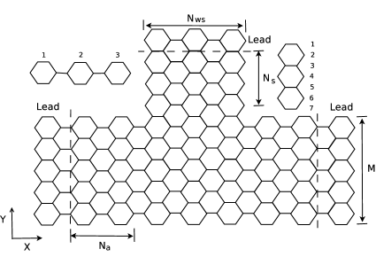
The T-shaped structure we study is composed of an armchair GNR of width connected to a sidearm of width , as schematically illustrated in the Fig. 1. We divide the system into four parts, the left, right and top leads as well as the central junction. The Hamiltonian of the system consists of the Hamiltonians for each part and their couplings . Using the tight-binding model under the nearest-neighbor approximation, the Hamiltonian are written as
| (1) | |||||
| (2) |
Here, is the hopping parameterChico et al. (1996) and , set to 0, is the on-site energy. denotes that the sum is restricted to the nearest neighbors.
Within the Landauer-Büttiker framework,Büttiker (1986) the transmission amplitude of the electrons with energy between leads and is
| (3) |
where and are the retarded/advanced Green’s function and the tunneling rate matrix, respectively. The retarded Green’s function is given by
| (4) |
in which, represents the retarded self-energy matrix. It can be expressed as , with and being the retarded surface Green’s function of lead and the hopping matrix between the lead and the central junction .Datta (1995) Similarly, one can write down the advanced Green’s function. The surface Green’s function can be calculated through an iterative scheme.Sancho et al. (1984) The tunneling rate matrix can be obtained from the self-energy,
| (5) |
The quasi-bound state is studied by diagonalizing the Hamiltonian numerically. The quasi-bound states can also be shown through the local density of state (LDOS), which can be obtained from the Green’s function.
III RESULTS
III.1 Localized states
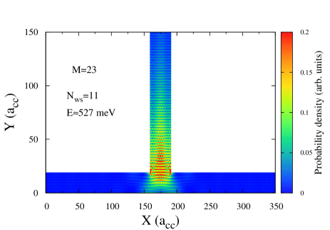
We first study the existence conditions of the quasi-bound states located at the intersection of the T-shaped GNRs. The states we are interested in are the ones whose eigen-energies are lower than the edges of the second sub-band of the leads. They are picked out according to the following rules: (1) the probability density of the state concentrates at the intersection; (2) the state is insensitive to the boundaries, that is, the state undergoes small changes when the lengths of the central junction ( or in Fig. 1) change. We find that the quasi-bound states exist in the structures only when the width ratio between the armchair GNR and sidearm is in certain regime. The conditions under which the quasi-bound states exist are listed in Table 1 for a wide range of the armchair GNR width , together with their eigenenergies. To show that these states are indeed trapped at the central junction, we plot the probability density for the quasi-bound state in Fig. 2 for a typical T-shaped GNR structure with , . One sees from the figure that for this state the electron indeed concentrates at the intersection. Moreover, the wave-function decays exponentially along the sidearm, but its amplitude along the two armchair GNRs is finite although small which implies that the state is a quasi-bound state. The localized components of the quasi-bound states, whose energy is below the second sub-band edges, mainly come from the second sub-band of the GNRs.Lin et al. (2001, 2002) Therefore, the probable condition for the quasi-bound state to exist is when the second sub-band edges of both the armchair GNR and the zigzag sidearm are comparable. In our setup the optimal condition for the quasi-bound states which is when is about , as it can be seen from Table 1.
| 11 | 5 (1079) | 23 | 10 (561), 11 (527) | |
| 14 | 6 (898) | 26 | 11 (500), 12 (480), 13 (457) | |
| 17 | 8 (712) | 29 | 12 (452), 13 (438), 14 (418) | |
| 20 | 9 (626), 10 (578) | 32 | 13 (420), 14 (406), 15 (379), | |
| 16 (366) |
III.2 Transport properties
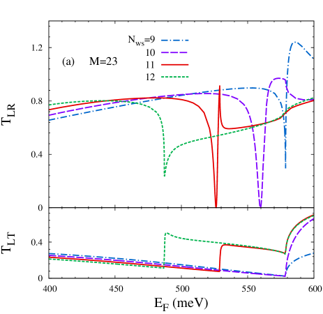
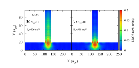
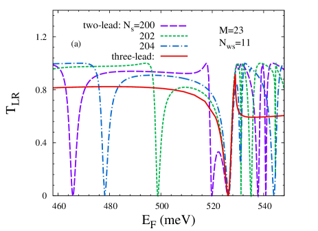
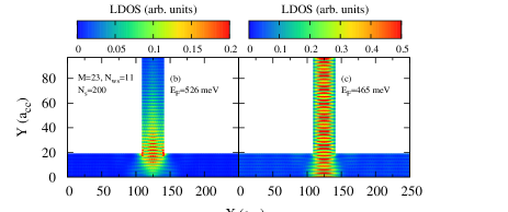
We now investigate the transport properties of T-shaped GNR structure. We concentrate on the energy range near the Dirac point. In Fig. 3(a) we plot the transmission amplitudes between the left and right leads (upper panel) and between the left lead and the sidearm (lower panel) as the functions of the electron energy for T-shaped GNR structure with the same width of the armchair GNR () but different sidearm widths. For , we have shown that the quasi-bound states exist only when and in the above section. The quasi-bound states have strong effect on the transmission between the left and right leads. One finds the a dip close to zero with an asymmetric line shape at meV for and a similar dip at meV for . The position of the dips are close to the corresponding eigen-energies of the quasi-bound states obtained from the diagonalization. The sharp dip near the eigen-energy of the quasi-bound state with an asymmetric line shape is the character of the Fano effect. Therefore one can see that the Fano effect strongly affects in the transmission between left and right leads. The sharp dip disappears when there is no quasi-bound state, as in the case of and . In the energy regime shown in the figure, there are only shallow dips for and at meV and meV, which are the second sub-band edge of the horizontal GNR for and that of the sidearm GNR for , respectively. The shallow dips at the sub-band edges are strongly related to the opening of new conduction channels, which can be clearly seen from the boost in accompanying these dips in as shown in the lower panel of Fig. 3(a). From the lower panel, one can also see that the quasi-bound states do not have any impact on the transmission between the left lead and the sidearm , since the quasi-bound states are localized along the sidearm. Additionally, the localization of the quasi-bound states is also identified by the local density of state in Fig. 3(b) and (c).
It should be further noted that the sharp dips caused by the Fano effect when the quasi-bound states exist should be distinguished from the ones due to the structure anti-resonance in the T-stub GNRs, i.e., without the lead connected to the sidearm.Sols et al. (1989a, b); Feng et al. (2007); Shen and Wu (2008); Weisshaar et al. (1989); Tekman and Bagwell (1993) In Figure 4(a) the transmission amplitudes for different sidearm lengths are plotted as functions of the energy for the T-stub GNR structure with and . One sees that apart from the sharp dip at meV caused by the quasi-bound state trapped at the central junction for all sidearm lengths, there are dips caused by the structure anti-resonance due to the resonance states in the T-stub.Sols et al. (1989a, b); Feng et al. (2007); Shen and Wu (2008); Weisshaar et al. (1989); Tekman and Bagwell (1993) Unlike the dip due to the quasi-bound state, the structure anti-resonance dips are sensitive to the sidearm length. To distinguish the quasi-bound state and the anti-resonance states, we also plot the LDOS corresponding to the Fano dip and a structure anti-resonance dip when in Figs. 4(b) and 4(c), respectively. It can be clearly seen that the quasi-bound state mainly concentrates at the intersection and while the anti-resonant state spreads over all of the entire sidearm.
IV SUMMARY
In summary, we have studied the quasi-bound states and the transport properties in the T-shaped GNR composed of a metallic armchair GNR and a zigzag sidearm. We systematically study the existence of the quasi-bound state in this structure for a wide range of the system size. We find that there are quasi-bound states when the width of the armchair GNR is about twice of sidearm width. The quasi-bound states are trapped at the intersection of the T-shaped junction and are truly localized along the sidearm direction. The quasi-bound states have strong effects on the transport between the two armchair leads but have no effect on the transport between the armchair lead and the sidearm. Due to these quasi-bound states, the Fano effect manifests through a characteristic dip with an asymmetrical line sharp in the energy dependence of transmission between the armchair leads.
Acknowledgements.
We would like to thank M.W.Wu for proposing the topic as well as directions during the investigation. This work was supported by the National Basic Research Program of China under Grant No. 2012CB922002 and the Strategic Priority Research Program of the Chinese Academy of Sciences under Grant No. XDB01000000.References
- Novoselov et al. (2004) K. S. Novoselov, A. K. Geim, S. V. Morozov, D. Jiang, Y. Zhang, S. V. Dubonos, I. V. Grigorieva, and A. A. Firsov, Science 306, 666 (2004).
- Geim and Novoselov (2007) A. K. Geim and K. S. Novoselov, Nature Mater. 6, 183 (2007).
- Geim (2009) A. K. Geim, Science 324, 1530 (2009).
- Castro et al. (2009) A. H. Castro, F. Guinea, N. M. R. Peres, K. S. Novoselov, and A. K. Geim, Rev. Mod. Phys. 81, 109 (2009).
- Sarma et al. (2011) S. D. Sarma, S. Adam, E. H. Hwang, and E. Rossi, Rev. Mod. Phys. 83, 407 (2011).
- Rozhkov et al. (2011) A. V. Rozhkov, G. Giavaras, Y. P. Bliokh, V. Freilikher, and F. Nori, Phys. Rep. 503, 77 (2011).
- Nguyen et al. (2009) V. H. Nguyen, V. N. Do, A. Bournel, V. L. Nguyen, and P. Dollfus, J. Appl. Phys. 106, 053710 (pages 7) (2009).
- Schwierz (2010) F. Schwierz, Nature Nanotech. 5, 487 (2010).
- Li et al. (2011) H. Li, Y. P. Chen, Y. E. Xie, and J. Zhong, J. Appl. Phys. 110, 033701 (pages 5) (2011).
- Tong and Wu (2012) H. Tong and M. W. Wu, Phys. Rev. B 85, 205433 (2012).
- González et al. (2011) J. W. González, M. Pacheco, L. Rosales, and P. A. Orellana, Phys. Rev. B 83, 155450 (2011).
- Guo et al. (2008) J. Guo, D. Gunlycke, and C. T. White, Appl. Phys. Lett. 92, 163109 (pages 3) (2008).
- Zhang et al. (2009) Z. Z. Zhang, Z. H. Wu, K. Chang, and F. M. Peeters, Nanotechnology 20, 415203 (2009).
- Li and Lu (2008) T. C. Li and S.-P. Lu, Phys. Rev. B 77, 085408 (2008).
- Bahamon et al. (2010) D. A. Bahamon, A. L. C. Pereira, and P. A. Schulz, Phys. Rev. B 82, 165438 (2010).
- Ouyang et al. (2009) F. P. Ouyang, J. Xiao, R. Guo, H. Zhang, and H. Xu, Nanotechnology 20, 055202 (2009).
- Jayasekera and Mintmire (2007) T. Jayasekera and J. W. Mintmire, Nanotechnology. 18, 424033 (2007).
- Andriotis and Menon (2008) A. N. Andriotis and M. Menon, Appl. Phys. Lett. 92, 163109 (2008).
- Schult et al. (1989) R. L. Schult, D. G. Ravenhall, and H. W. Wyld, Phys. Rev. B 39, 5476 (1989).
- Openov (2001) L. A. Openov, Europhys. Lett. 55, 539 (2001).
- Fano (1961) U. Fano, Phys. Rev. 124, 1866 (1961).
- Miroshnichenko et al. (2010) A. E. Miroshnichenko, S. Flach, and Y. S. Kivshar, Rev. Mod. Phys. 82, 2257 (2010).
- Shen and Wu (2008) K. Shen and M. W. Wu, Phys. Rev. B 77, 193305 (2008).
- Wang et al. (2008) L. Wang, K. Shen, S. Y. Cho, and M. W. Wu, J. Appl. Phys. 104, 123709 (pages 4) (2008).
- Lin et al. (2001) Y.-K. Lin, Y.-N. Chen, and D.-S. Chuu, Phys. Rev. B 64, 193316 (2001).
- Lin et al. (2002) Y.-K. Lin, Y.-N. Chen, and D.-S. Chuu, J. Appl. Phys. 91, 3054 (2002).
- Goldoni et al. (1997) G. Goldoni, F. Rossi, and E. Molinari, Appl. Phys. Lett. 71, 1519 (1997).
- Baranger (1990) H. U. Baranger, Phys. Rev. B 42, 11479 (1990).
- Chen et al. (2005) Y. P. Chen, X. H. Yan, and Y. E. Xie, Phys. Rev. B 71, 245335 (2005).
- Bohn (1997) J. L. Bohn, Phys. Rev. B 56, 4132 (1997).
- Nakada et al. (1996) K. Nakada, M. Fujita, G. Dresselhaus, and M. S. Dresselhaus, Phys. Rev. B 54, 17954 (1996).
- Wakabayashi et al. (1999) K. Wakabayashi, M. Fujita, H. Ajiki, and M. Sigrist, Phys. Rev. B 59, 8271 (1999).
- Chico et al. (1996) L. Chico, V. H. Crespi, L. X. Benedict, S. G. Louie, and M. L. Cohen, Phys. Rev. Lett. 76, 971 (1996).
- Büttiker (1986) M. Büttiker, Phys. Rev. Lett. 57, 1761 (1986).
- Datta (1995) S. Datta, Electronic Transport in Mesoscopic System (Cambridge University Press, New York, New York, 1995).
- Sancho et al. (1984) M. P. L. Sancho, J. M. L. Sancho, and J. Rubio, J. Phys. F: Met. Phys. 14, 1205 (1984).
- Sols et al. (1989a) F. Sols, M. Macucci, U. Ravaioli, and K. Hess, J. Appl. Phys. 66, 3892 (1989a).
- Sols et al. (1989b) F. Sols, M. Macucci, U. Ravaioli, and K. Hess, Appl. Phys. Lett. 54, 350 (1989b).
- Feng et al. (2007) X. Y. Feng, J. H. Jiang, and M. Q. Weng, Appl. Phys. Lett. 90, 142503 (pages 3) (2007).
- Weisshaar et al. (1989) A. Weisshaar, J. Lary, S. M. Goodnick, and V. K. Tripathi, Appl. Phys. Lett. 55, 2114 (1989).
- Tekman and Bagwell (1993) E. Tekman and P. F. Bagwell, Phys. Rev. B 48, 2553 (1993).