Development of High Intensity Laser-Electron Photon Beams up to 2.9 GeV at the SPring-8 LEPS Beamline
Abstract
A laser-Compton backscattering beam, which we call a ‘Laser-Electron Photon’ beam, was upgraded at the LEPS beamline of SPring-8. We accomplished the gains in backscattered photon beam intensities by factors of 1.5–1.8 with the injection of two adjacent laser beams or a higher power laser beam into the storage ring. The maximum energy of the photon beam was also extended from 2.4 GeV to 2.9 GeV with deep-ultraviolet lasers. The upgraded beams have been utilized for hadron photoproduction experiments at the LEPS beamline. Based on the developed methods, we plan the simultaneous injection of four high power laser beams at the LEPS2 beamline, which has been newly constructed at SPring-8. As a simulation result, we expect an order of magnitude higher intensities close to 107 sec-1 and 106 sec-1 for tagged photons up to 2.4 GeV and 2.9 GeV, respectively.
keywords:
Laser-Compton backscattering , High energy photons , High intensity beam , Electron storage ring , Hadron photoproduction experiment1 Introduction
Backward Compton scattering of laser light from a high energy electron beam [1, 2] is a popular technique to produce -ray beams in a wide energy range. We refer to such a -ray beam as a ‘Laser-Electron Photon’ (LEP) beam. In the last decade, several facilities to produce the LEP beam have been successfully operated at high-current electron storage rings, where the coexistence with synchrotron radiation light sources is reasonably achieved. Energies of backscattered photons can be magnified nearly up to the same order of magnitude as the electron beam energy by injecting ultraviolet (UV) laser light into a multi-GeV storage ring. The LEP beams generated in this way at the energies from 100 MeV to a few GeV have been used in the experiments for hadron and nuclear physics, as summarized in Ref. [3, 4]. The number of facilities with low energy beams up to a few tens MeV using an infrared (IR) laser or a low energy storage ring is also increasing for nuclear physics and astrophysics [5, 6, 7, 8, 9].
The LEP beam possesses several advantages for the physics experiments as follows: Firstly, a photon beam is clean without hadron contaminations. Although pair-created electrons and positrons are unavoidably contaminated, they are removed by a sweeping magnetic field, a charge veto counter, and a erenkov counter. Secondly, a spread of the backscattered photon directions is roughly equivalent to a polar angle of 1/ rad, where represents the Lorentz factor for multi-GeV electrons. A collimated beam can be provided to an experimental site. Thirdly, an energy spectrum of the LEP beam is rather flat below the Compton edge, compared with that of a bremsstrahlung photon beam. Backgrounds due to low energy photon reactions, which are usually untagged, are relatively suppressed in the case of the LEP beam. Finally, a LEP beam possesses nearly 100% polarization at the maximum energy because laser polarization is retained at a hard head-on collision of a laser photon and an electron. A polarization vector of the LEP beam is easily controllable by handling the laser polarization, which can be linear, circular, or elliptical.
So far, the highest LEP energy region has been covered by the LEPS beamline at SPring-8 [10], which stores 7.975 GeV electrons with a current of 100 mA. From a kinematical calculation, the maximum energy of the LEP beam () is given by:
| (1) |
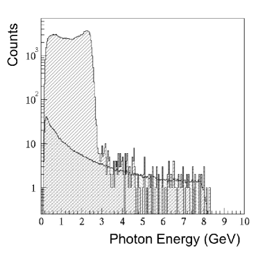
where , , and represent the energy, momentum, and mass of an electron in the storage ring, respectively, and denotes the energy of laser light. At an early stage of the LEPS experiments, a multiline UV argon-gas laser (Ar laser) with output wavelengths around 351 nm was operated [11] as done widely in other facilities. A LEP energy spectrum with the Ar laser has been observed as shown in Fig. 1, indicating the maximum energy of 2.4 GeV in accordance with Eq. 1. In Fig. 1, a spectrum for bremsstrahlung photons, arising from the electron deceleration by a residual gas inside the storage ring, is overlaid by normalizing event entries in the energy range above 2.4 GeV. The comparison of the two spectra suggests that the intensity of a LEP beam is more than two orders of magnitude higher than that of a bremsstrahlung photon beam. The generated LEP beam was transported to a fixed target made of liquid hydrogen or deuterium. The liquid target was sometimes replaced to a solid nuclear target. Structures and interactions of hadrons, particularly including a strange quark, have been studied by measuring differential cross sections and polarization observables in the photoproduction from those targets, as summarized in Ref. [3].
Although the LEP beam production by using the Ar laser has been established with the successful results, further improvements concerning the beam intensity and the maximum energy are desired to advance hadron and nuclear physics. Firstly, an interaction rate of a photon beam is lower than that of a hadron beam, so that a higher intensity LEP beam is needed for precise and systematic measurements. For this purpose, a method to inject multiple laser beams has been developed as discussed later. In addition, a UV output power is increasing thanks to the progress in the technologies of all-solid lasers. Secondly, the extension of the maximum LEP energy opens new fields of the photoproduction experiments. For example, it becomes feasible to study the photoproduction of heavy particles, like the K∗(892) production in the t-channel. A recoilless condition of and mesons, which are produced inside a nucleus, is also achieved at 2.75 GeV, possibly making nuclear medium modification more efficient. High power deep-UV (DUV) lasers with a shorter wavelength are now available, and the production of a high energy LEP beam is hence realistic as recognized from Eq. 1.
The following part of the present article describes the results on the intensity and energy upgrades at the LEPS beamline together with the studies for a near-future project. In Section 2, experimental setups for the LEP beam production and upgrades are explained in addition to the methods of intensity and energy measurements. In Section 3, we discuss the results obtained by introducing the new solid-state laser, the DUV lasers, and the simultaneous two-laser injection method. In Section 4, we argue new attempts to increase a LEP intensity and simulation studies for a new beamline, whose construction has just finished for carrying out next-generation experiments at SPring-8. Finally, a brief summary follows in Section 5.
2 Experimental Setup
2.1 UV and DUV Lasers
Table 1 shows the properties of the UV lasers which have been used at the LEPS experiments. The Ar laser (‘Innova Sabre’) was operated from the beginning of the experiments, which started in 1999. It provides an output power of 7 W with three major contributions from the wavelengths of 333.6–335.8 nm, 351.1 nm, and 363.8 nm. These contributions produce the Compton edges at 2.49 GeV, 2.40 GeV, and 2.34 GeV, respectively, with the strengths similar to each other. For the discharge inside an argon-gas tube, the whole system typically required 10 kW electric power consumption with a three-phase AC input of 480 V. Since 2006, the ‘Innova Sabre’ has been replaced to the solid-state laser ‘Paladin’ with a UV output power of 8 W. Its power consumption is reduced to 350 W with a 100 V / 200 V AC power supply. This low power consumption is achieved by introducing a combination of a seed laser diode and a nonlinear crystal, which triples a seed laser frequency by third harmonic generation (THG). The output wavelength of the ‘Paladin’ is only 355 nm, and the Compton edge of the LEP beam with this laser has become 2.39 GeV. In Sections 3.1 and 3.3, the ‘Paladin’ with the 8 W UV power (8 W ‘Paladin’) was used for further development of LEP beams. An upgraded version of this laser with an output power of 16 W (16 W ‘Paladin’) was also tested as described in Section 4.1.
| Laser name | Innova Sabre | Paladin | Paladin |
|---|---|---|---|
| DBW25/7 | 355-8000 | 355-16000 | |
| (Coherent Inc.) | (Coherent Inc.) | (Coherent Inc.) | |
| Wavelength | multiline UV | 355 nm | 355 nm |
| 333.6–363.8 nm | |||
| Emission frequency | CW | 80 MHz | 80 MHz |
| (quasi-CW) | (quasi-CW) | ||
| UV output power | 7 W | 8 W | 16 W |
| diameter | 1.7 mm | 1.0 mm | 1.35 mm |
| Divergence | 0.31 mrad | 0.55 mrad | 0.55 mrad |
| Power consumption | 10 kW | 350 W | 350 W |
The DUV lasers which are listed in Table 2 have been introduced for the extension of the maximum energy at the LEPS beamline. All the lasers supplies a continuous-wave (CW) beam with a shorter wavelength of 257 nm or 266 nm, which is achieved by doubling the frequency of a seed green laser (second harmonic generation, SHG) at a Barium Borate (BBO) crystal. After confirming a LEP energy spectrum by using ‘DeltaTrain’ as described in Section 3.2, the collection of large physics data have been done with ‘Innova Sabre Moto FreD’ and ‘Frequad-HP’, whose output powers are both 1 W. A seed laser of the ‘Innova Sabre Moto FreD’ is the argon-gas tube system, which has been operated as the resonator of the ‘Innova Sabre’, and it requires huge power consumption. Therefore, the method of two-laser injection has been developed by using the ‘Frequad-HP’, which is an all-solid DUV laser. The LEP beam intensities with these lasers and the two-laser injection are discussed in Sections 3.2 and 3.3, respectively.
| Laser name | DeltaTrain | Innova Sabre | Frequad-HP |
|---|---|---|---|
| (Spectra-Physics | Moto FreD | (Oxide Corp.) | |
| Inc.) | (Coherent Inc.) | ||
| Wavelength | 266 nm | 257.2 nm | 266 nm |
| Emission frequency | CW | CW | CW |
| UV output power | 0.7 W | 1 W | 1 W |
| diameter | 0.5–0.6 mm | 0.6–0.9 mm | 3.0 mm |
| Divergence | 0.6–0.9 mrad | 0.5–0.85 mrad | 0.4 mrad |
| Power consumption | 370 W | 10 kW | 300 W |
2.2 Laser Beam Focus
We developed several methods to improve the LEP beam properties at the LEPS beamline (BL33LEP) of SPring-8. Figure 2 shows a schematic view of the experimental setup to inject laser beams into the electron storage ring. The whole injection system was set up inside the laser hutch, which is an interlocked radiation shield room beside a thick concrete wall of the ring tunnel. Lasers and injection optics were placed on a large surface plate with coverage by a clean booth. Since the injected laser light collides with a narrow electron beam at the straight section of the storage ring after traveling a distance of 37 m, it is necessary to introduce a beam expander, which once enlarges a laser diameter for making a focus (or a beam waist) at the collision point. For an ideal Gaussian beam, a or 2 radius ( [mm]) at an arbitrary distance from the focus point ( [m]) is uniquely determined by a desired waist radius ( [mm]) as described with the following equation:
| (2) |
where represents a wavelength of the laser in nm. In our case with the 8 W ‘Paladin’, the radius around the beam waist is calculated as shown in Fig. 3. Because the average standard deviations () of the electron beam at the straight section are 295 m and 12 m in the horizontal and vertical directions, respectively, the radius desired for the laser beam waist is about 300 m from an average of the two electron beam sizes. Consequently, the magnification factors to determine the output diameters from the beam expanders were set to 28.6 and 13.3 for the laser light from the 8 W ‘Paladin’ and the ‘Frequad-HP’, respectively.
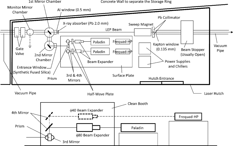

A structure of the beam expander is the same as a Galilean telescope, which increases an input laser diameter at a set of small concave lenses and outputs a convergent beam from a large convex lens. These optical lenses were made of high grade synthetic fused silica, which minimizes chemical impurities in order to reduce the generation of color centers by a high power laser. In contrast, a modest amount of hydroxyl (OH) concentrations at 1000 ppm is accepted for UV radiation resistance [13]. Beam expanders for UV and DUV lasers were separately prepared to ensure high transmission rates with individually optimized anti-reflection (AR) coating on the lens surfaces. The convex lens diameter at the expander output was set to 40 mm (40) for the DUV laser, while this diameter was enlarged to 80 mm (80) for the UV laser in order to enable the transformation of a laser beam shape as described in Section 4.2. In the measurements of beam intensities, a focal length was adjusted to increase the laser-electron collision rate at best by changing the length between concave lenses and a convex lens with a micrometer.
2.3 Laser Injection Methods
A laser beam enlarged at the beam expander was reflected at two high-reflection (HR) coated mirrors, indicated as the third and fourth mirrors in Fig. 2, before the injection into vacuum chambers. These two mirrors, whose diameters were designed to be 80 mm, were mounted on a set of micro-stepping motors for a remote control of horizontal rotation and vertical elevation angles. In this scheme, angle variations and parallel shifts of a laser beam are possible for the precise adjustment of its axis relative to the electron beam. The LEP beam intensities with the injection of a single laser beam were basically measured by this mirror setup or putting an additional mirror with a large effective area. A linear polarization vector of a laser beam was controlled by a quartz half-wave () plate, whose diameter was 48 mm. It was placed just after the beam expander output in order to avoid a damage by a high laser power density. A direction of the linear polarization was switched vertically or horizontally by rotating the plate. In the LEP intensity measurements described below, the plate was sometimes taken out from the laser path.
For the purpose of simultaneous injection with two UV lasers, we put two ‘Paladin’ lasers in parallel as shown in Fig. 2. In the rear space of them, we placed two ‘Frequad-HP’ lasers on a higher stage for another simultaneous injection of DUV laser beams. Two sets of the 80 beam expanders with manual linear and rotation stages were installed in front of the ‘Paladin’ lasers, while they were replaced to the beam expanders with higher stages in the case of using the ‘Frequad-HP’ lasers. Two laser beams, which were reflected at the third and fourth mirrors, were incident on a right-angle prism from opposite sides, so that both beam paths were directed to the storage ring side by side after the reflections at two perpendicular planes with HR coating. Since the LEP intensity became higher when a laser injection angle was close to the condition of a head-on collision with the electron beam, the spacial position of the prism was adjusted by three perpendicular linear stages. Laser beams were incident near the storage ring-side edge on the reflection planes, whose width was 56.6 mm and 42.4 mm for the UV and DUV laser injection, respectively. The prism size for the DUV laser injection was slightly smaller than the laser beam cross section, and this effect was taken into account in Section 3.3.
Alternative method of two-laser injection, which accomplishes complete head-on collisions, may be possible by using a polarizing beamsplitter and overlapping two beams with linear polarizations normal to each other. However, we chose the method using a prism because the polarization vectors of two beams can be aligned in the same direction as each other. The third and fourth mirrors and the prism, all of which were made of synthetic fused silica, were separately prepared for the UV and DUV lasers in order to optimize HR coating to the individual wavelengths. We changed those optics alternatively depending on the injected laser beams.
2.4 The LEPS Beamline
A laser beam was finally injected into vacuum chambers, connected to the storage ring with the ultrahigh vacuum of Pa. An entrance window of the vacuum chamber is made of a 4 mm-thick synthetic fused silica, which is mounted on an ICF-114 flange and possesses the effective area with a 60 mm diameter. The injected laser beam was further reflected twice at aluminum coated silicon mirrors toward the straight section of the storage ring. These mirrors are called the first and second mirrors as shown in Fig. 2. Thickness of the second mirror was designed to be 19 mm for ensuring surface accuracy, while that of the first mirror was reduced to 6 mm because a LEP beam passes through this mirror. Since X-rays due to synchrotron radiation are irradiated onto the first mirror, it was cooled by a water flow from a rear holder, which has a hole for the LEP beam path.
During a long-term use of these two mirrors and the entrance window under a high radiation environment, we observed a drop of reflection and transmission rates for both UV and DUV laser light due to the attachment of hydrocarbons from a residual gas inside the chambers. Figure 4 shows the change of a total transmission rate for the propagation through those optical components as a function of beam time (or total time under radiation exposure) at the LEPS experiments. The transmission rate was measured by taking a ratio of laser powers before injecting the laser light to the entrance window and after extracting it from the monitor mirror chamber, indicated in Fig. 2. From a fit for all the data points in the upper and lower panels of Fig. 4, we have found this transmission rate () changes by following:
| (3) |
where denotes the beam time in the unit of days. It turns out that decreasing rates of the transmissions for UV and DUV wavelengths are similar to each other. Due to the observed deterioration, the entrance window and the first and second mirrors have been periodically replaced in each 1–2 years.

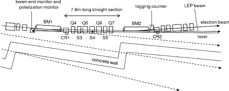
The laser beam reaches the 7.8 m-long straight section, whose center is the backscattering point. Figure 5 shows a plan view of the LEPS beamline around the straight section. An appropriate laser path was searched for by adjusting the third and fourth mirror angles and confirming the laser spot position at three monitor ports, where an insertion mirror or screen was prepared. In Fig. 5, one of such monitor ports is indicated as the ‘beam end monitor’. The best path was then achieved by maximizing a laser-electron collision rate with the optimizations of mirror angles and a prism position. Since the apertures of beamline chambers are limited due to X-ray masks and magnets, the laser light only within a 40 mm 40 mm square region at the entrance window can pass to the collision point. While the laser beam path in single-laser injection is not affected by the aperture size, the propagation of two adjacent laser beams injected simultaneously is prevented by the limit of 20 mm on the horizontal width per beam. The width of 20 mm corresponds to 1.4 and 1 in the horizontal distributions of laser powers when using the ‘Paladin’ and the ‘Frequad-HP’, respectively. This aperture effect was taken into account in Section 3.3.
A backscattered photon beam, whose energy is magnified up to a GeV scale, travels the ultrahigh vacuum beamline in the direction opposite to the laser beams. After passing through the first mirror, the photon beam is extracted from a 0.5 mm-thick aluminum window of the vacuum chamber inside the laser hutch. (See Fig. 2.) X-rays in the beam are absorbed by a 2.0 mm-thick lead plate, mounted on the aluminum window. The contamination from e+e- pair creations at the first mirror, the aluminum window, and the lead absorber is removed by a sweep magnet, which provides a dipole magnetic field of 0.6 Tesla. The cleaned-up photon beam is then transported from the laser hutch to an experimental site, which is located about 70 m downstream from the laser-electron collision point, through a medium vacuum pipe with 1 Pa. A total transmission rate of the LEP beam from the collision point to the experimental site was unavoidably reduced to about 60% by the pair-creations, mentioned above. More details of the LEPS beamline facility are described in Ref. [3].
2.5 Intensity Measurement
In the following sections, LEP beam intensities and energies were measured by a tagging detector (or a ‘tagger’), which counts number of recoil electrons in the backward Compton scattering and analyzes momenta of them event by event. The tagger was installed at the electron beam exit of a bending magnet chamber, as shown in Fig. 5. A recoil electron track is distinguished from an electron beam orbit by a dipole magnetic field of 0.68 Tesla. Typically, a deviation by 1 mm for the tagger hit position corresponds to a 30 MeV/c difference of the recoil electron momentum. At early stages of the LEPS experiments, the tagger was constructed from 10 fingers of trigger scintillators and a 100 m-pitch silicon-strip detector (SSD) with two layers. The LEP energy spectrum discussed in Section 3.2 was measured by this configuration. From the year 2005, the SSD part has been replaced to 1 mm-square scintillation fibers with a 0.5 mm shift at different layers. The photon energy was evaluated by subtracting the momentum of a recoil electron from the storage ring energy of 7.975 GeV. A geometrical acceptance of the tagger restricts the measurable range of the recoil electron momentum, so that the backscattered photons are tagged at 1.5 GeV. Based on the integrations of the backward Compton scattering spectra, the fractions of tagged LEP intensities relative to the true intensities in the overall energy range are calculated to be 38% and 47% for the injection of 355 nm UV and 266 nm DUV laser light, respectively. A resolution of the measured LEP energy has been estimated to be 12 MeV, which is dominated not by a position resolution of the tagger but by an electron beam divergence at the straight section.
In the LEP intensity measurements by the tagger scintillators, dead time is caused mainly by the rejection of accepting trigger hits during the time width of a preceding signal. The dead time was originally 105 nsec for the tagger with a SSD, but it was changed when the tagger was updated with scintillating fibers and the trigger logic was slightly modified. Most of the following intensity measurements were performed with the dead time of 38 nsec. A correction factor to be multiplied to the measured tagger rate was evaluated from the ratio of hits rejected by the dead time in a random number simulation. This ratio depends on the filling pattern of electrons, which are bunched inside the storage ring to 13 psec length by the 508.58 MHz RF frequency corresponding to the minimum interval of 1.966 nsec. There are several variations for the filling pattern of electron bunches, for example, by making a few hundreds of bunches isotropic on the circumference of 1,436 m, or by filling several single bunches and a long bunch train [10]. An isotropic filling pattern generally lowers the correction factor. The correction factor also varies depending on the laser-electron collision rate. Therefore, it was formulated as a function of the measured tagger rate for the individual filling pattern. While the correction for dead time loss is applied in the following intensity measurements, we have not converted the tagged LEP intensities to the values in the whole range.
3 Results of Photon Beam Upgrades
3.1 Photon Beam Production using an All-Solid Mode-Lock UV Laser
The operation of an Ar laser (‘Innova Sabre’) needs a large electric power supply and a huge cooling water flow because of large power consumption as described in Section 2.1. In addition, a periodical replacement of the argon-gas tube was necessary to keep a reasonable output power. Hence, we have introduced an all-solid mode-lock UV laser (8 W ‘Paladin’), whose electric power consumption is significantly reduced and which requires only an internal water circulation from an air-cooled chiller. The reduced power consumption also makes it possible to operate multiple lasers simultaneously, as being discussed in Section 3.3. A laser pointing at the 37 m-downstream focus and a UV output power of 8 W are reasonably stable over several thousand hours, while the nonlinear THG crystal must be occasionally shifted to avoid a damaged laser spot. Laser emission from the ‘Paladin’ is pulsed with a frequency of 80 MHz in a quasi-CW mode. Although the electron beam is also bunched, a laser beam around the collision point possesses a beam waist with a Rayleigh range of 0.8 m as shown in Fig. 3. The 7.975 GeV electron encounters the 80 MHz laser photons at each 1.875 m, which is roughly equivalent to twice the Rayleigh range. In addition, the minimum electron bunch interval of 1.966 nsec, corresponding to a running distance of 0.6 m, is small enough compared with the Rayleigh range. Therefore, this pulsed laser beam sufficiently collides with electrons.
| Injected laser | 8 W Paladin | Innova Sabre (7 W) | ||
|---|---|---|---|---|
| Polarization | Vertical | Horizontal | Vertical | Horizontal |
| w/ /2 plate | w/ /2 plate | w/ /2 plate | w/ /2 plate | |
| Tagger rate | 1.15 MHz | 0.99 MHz | 0.84 MHz | 0.99 MHz |
| e- beam current | 100 mA | 100 mA | 60.8 mA | 83.5 mA |
| Filling pattern | 203 bunch | 203 bunch | 203 bunch | 203 bunch |
| 4 bunch 7 | 4 bunch 7 | |||
| Tagger dead time | 38 nsec | 38 nsec | 105 nsec | 105 nsec |
| (Dead time corr.) | (1.043) | (1.036) | (1.107) | (1.131) |
| Beam time | 184 days | 184 days | 40 days | 40 days |
| (Corr. factor) | (—) | (—) | (0.631) | (0.631) |
| LEP intensity | 1.20 MHz | 1.03 MHz | 0.96 MHz | 0.85 MHz |
| for | ||||
A LEP beam intensity with the 8 W ‘Paladin’ was calculated from a tagger rate and a dead time correction factor, as described in Section 2.5. Table 3 summarizes the intensity calculations for the typical experimental cycles covering 1–2 weeks. The tagger rate was measured in two cases, where a linear polarization vector of the injected laser light was aligned in the vertical or horizontal direction. For comparisons, corresponding numbers in the case of using the ‘Innova Sabre’ are also shown. Thanks to a top-up operation, which keeps electron beam injection into the storage ring every one minute or less, the tagger rates with the 8 W ‘Paladin’ were always measured with an electron beam current of 100 mA. In contrast, the measurements with the ‘Innova Sabre’ were done before the start of the top-up operation, so that the beam current of the storage ring decreased with a life of a few tens to hundred hours depending on an electron filling pattern. Thus, average currents of the electron beam during the intensity measurements were evaluated for further corrections, as written in Table 3. All the tagger rates were measured in the periods when 203 electron bunches were isotropically filled in a circumference of the storage ring or such a filling pattern was modified by removing 4 adjacent bunches from every 29 bunches. The difference of correction factors for the tagger dead time arises not from the filling pattern but from the variation of measured tagger rate and the change of dead time.
In the case we used the 8 W ‘Paladin’, the tagged LEP intensities at the photon energies above 1.5 GeV were 1.20106 sec-1 and 1.03106 sec-1 for the vertical and horizontal polarizations, respectively. The tagged beam intensity of 106 sec-1 is well reproduced by a naive model, where a ‘tube’-like flux of 355 nm laser light (150 m) encounters a 100 mA electron beam (295 m and 12 m) with the backscattering cross section of 0.20 barn at the interaction region defined by twice the Rayleigh range. By comparing the two measurements for different polarization states, we observed that the LEP beam intensity with the injection of vertically polarized laser light was about 17% higher than that with the horizontally polarized laser injection. This is caused by two horizontal reflections of laser light at the first and second mirrors, which are coated by aluminum. Based on the calculation with Fresnel coefficients at a 45∘ angle of incidence [14], a reflection rate of S-polarized UV light, whose electric field direction is perpendicular to a plane of incidence, is 6% higher than that of P-polarized one, whose electric field orientation is parallel to the same plane. Thus, about 11% difference is expected for the two successive reflections. This value is not far from the observed difference, and the actual measurements must be affected by surface oxidation and degradation.
The LEP beam intensities with the ‘Innova Sabre’ were measured to be 0.96106 sec-1 and 0.85106 sec-1 for the vertical and horizontal polarizations, respectively. These intensities have been corrected by taking into account the tagger dead time and the normalization at the electron beam current of 100 mA. In addition, the difference of a laser transmission rate relative to the case with the ‘Paladin’ has been cancelled by scaling the intensities at the beam time of 184 days. Table 3 suggests that the LEP beam intensity has been actually raised up after introducing the 8 W ‘Paladin’. This improvement was achieved by a slight increase of the laser power and better optimizations of laser injection optics. It is also important that the top-up operation of the storage ring and the long-term stability of the laser power have largely contributed to the net increase of LEP intensity.
3.2 Extension of the Maximum Photon Energy using DUV Lasers
The maximum energy of a LEP beam is extended by using a shorter wavelength laser, as discussed in Section 1. CW lasers with a power output of about 1 W are currently available for the DUV wavelength of 266 nm or 257 nm, as described in Section 2.1. The generation of such a higher energy LEP beam was first confirmed by operating a 266 nm laser (‘DeltaTrain’). An energy spectrum of the LEP beam was measured by the old tagger with a SSD, and the tagger energy calibration was done by analyzing special data, where e+e- pair production events from a bremsstrahlung photon beam were collected by putting a 0.5 mm-thick lead converter plate at the LEPS experimental site. For the tagger calibration, momenta of the e+ and e- tracks were measured using the LEPS spectrometer [3, 11] with the particle identification by time-of-flight, and the measured momenta were corrected by taking into account the energy loss due to bremssstrahlung radiation at the lead plate and detector materials. The relation between the measured photon energies, which were defined as a sum of the e+ and e- momenta, and the tagger SSD hit positions was formulated by fitting a second order polynomial function. A LEP energy spectrum was then obtained by applying this energy calibration function to a raw distribution of tagger SSD hit positions, which were recorded in the data accumulated by the tagger scintillator triggers with the 266 nm laser injection. Here, good tagger hits were selected if a recoil electron track was reconstructed by the two SSD layers and the trigger scintillators. Figure 6 shows the obtained spectrum after correcting the efficiencies of tagger scintillators. The spectrum is largely fluctuated because of variations in SSD strip efficiencies. The energy region lower than 1.9 GeV is not plotted because of a SSD module problem in this measurement. By fitting a template spectrum from a backward Compton scattering simulator, it was confirmed that the Compton edge was extended up to 2.89 GeV as expected.

A typical DUV output power of the ‘DeltaTrain’ was 0.7 W, and frequent manual adjustments of inner optics were required. For physics data taking, a DUV laser based on an argon-gas tube with a BBO crystal (‘Innova Sabre Moto Fred’) was instead introduced. An output wavelength of this laser was 257.2 nm, so that the maximum energy of a LEP beam slightly increased up to 2.96 GeV. Its output power was around 1 W, while there was variation depending on a seed laser power. The tagger rates with this laser were measured for the two polarization states during a typical experimental cycle, as shown in the left part of Table 4. Tagger dead time corrections for an isotropic filling of 203 electron bunches were estimated to be small because of low tagger rates. The corrected LEP beam intensities at 1.5 GeV were 0.21106 sec-1 and 0.16106 sec-1 for the vertical and horizontal polarizations, respectively. These LEP intensities are about one-tenth of those with the 8 W ‘Paladin’, as recognized from the comparison of Tables 3 and 4 together with taking into account about 40% reduction of the UV light transmission due to the additional radiation exposure of 161 days. The observed reduction by an order of magnitude can be understood by multiplying the ratios of laser powers (1 W / 8 W), laser photon energies (257 nm / 355 nm), backward Compton scattering cross sections (0.15 barn / 0.20 barn), and tagged energy ranges (47% / 38%). The LEP beam whose energy was extended up to 3 GeV with the ‘Innova Sabre Moto Fred’ was utilized for a few years, resulting in wide physics outcomes as described in Ref. [15, 16].
| Injected laser | Innova Sabre Moto Fred | Frequad-HP | ||
|---|---|---|---|---|
| Polarization | Vertical | Horizontal | Vertical | Horizontal |
| w/ /2 plate | w/ /2 plate | w/ /2 plate | w/ /2 plate | |
| Tagger rate | 0.21 MHz | 0.16 MHz | 0.25 MHz | 0.21 MHz |
| Filling pattern | 203 bunch | 203 bunch | 203 bunch | 203 bunch |
| (Dead time corr.) | (1.007) | (1.005) | (1.009) | (1.007) |
| LEP intensity | 0.21 MHz | 0.16 MHz | 0.25 MHz | 0.22 MHz |
| for | ||||
During the operation of the ‘Innova Sabre Moto Fred’, the BBO crystal for SHG had to be shifted frequently because the lifetime of a laser-irradiated spot was typically 1–2 weeks. In addition, the argon-gas tube system as a seed laser caused huge power consumption and required its periodical replacements. Therefore, we have changed it to a new solid-state DUV laser (‘Frequad-HP’), which provides CW emission with a wavelength of 266 nm. The ‘Frequad-HP’ has accomplished the low power consumption of 300 W only with air cooling by adopting two stages of SHG from an IR diode laser. This feature enables simultaneous two-laser injection as discussed in Section 3.3. A fixed output of 1 W stably lasts over a few thousand hours because of a significant improvement of a BBO crystal purity, which also increases a SHG efficiency up to 20%. The right part of Table 4 shows the results of LEP intensity measurements with the ‘Frequad-HP’. For comparison with the case of the ‘Innova Sabre Moto Fred’, we examined tagger rates under similar conditions about the filling pattern and the beam time. The tagged LEP beam intensities were evaluated to be 0.25106 sec-1 and 0.22106 sec-1 for the vertical and horizontal polarizations, respectively. These values are slightly larger than those with the ‘Innova Sabre Moto Fred’. There was a gain by the stable DUV output. We had found that a narrow and high power beam from a DUV laser seriously damaged the AR coating on the concave lens of a beam expander. However, this damage was minimized enough after a power density was lowered by using the ‘Frequad-HP’, whose beam diameter was increased to 3.0 mm. This also contributed to obtaining a gain of the LEP intensity during a long term data taking.
3.3 Increasing Beam Intensities by Two-Laser Injection
In principle, the flux of photons to be collided with electron beam is proportional to the number of injected lasers. As already discussed, the simultaneous operation of multiple lasers is now possible for both UV and DUV wavelengths at the LEPS experiments. Table 5 shows the results of LEP intensity measurements with the simultaneous injection of two laser beams. The position of a prism, merging two laser beams, was scanned in the three dimensional space in order to maximize tagger rates. At its optimum position, the condition close to head-on collisions was satisfied, giving small injection angles with moderate cutoffs of the expanded laser cross sections by the common edge of two reflection planes. The measured tagger rate was corrected by the trigger dead time. Since the tagger rates in this test were measured as short-time averages, the measurement error of them was about 10%. In order to estimate the intensity gain, the tagger rate with single-laser injection was also measured by rescanning the prism position, where a complete head-on collision was achieved with the minimum cutoff of a laser cross section at a reflection plane. This measurement was repeated twice for the two lasers, which were used for the simultaneous injection. The two results were averaged in Table 5. The LEP beam intensities with the simultaneous two-laser injection increased by factors of 1.5 and 1.6 in the cases of using the ‘Paladin’ and the ‘Frequad-HP’, respectively. High statistics data collected with the two-laser injection is being analyzed for the studies of exotic hadrons and so on [16, 17].
As explained in Section 2.4, the geometrical acceptance due to the beamline aperture limits the LEP intensity gain of the two-laser injection. In order to estimate the acceptance-corrected gain factors expected at a larger aperture beamline, correction factors were computed from the ratio of masked area in the laser cross section, as shown in Table 5. For the case of single-laser injection, the correction for the beamline aperture is not needed, but a finite prism size restricts the horizontal width of laser beam paths as mentioned in Section 2.3. Therefore, a small correction factor due to this beam cutoff was obtained to estimate the true gain expected with a larger prism, as shown in Table 5. The prism size correction was not taken into account in the case of two-laser injection because that size was large enough compared with the limitation from the beamline aperture. If all of these corrections are adopted, the acceptance-corrected gain factors of LEP beam intensities by the two-laser injection must reach 1.6 and 1.8 for the use of the ‘Paladin’ and the ‘Frequad-HP’, respectively. These gain factors are close to two, while there is reduction by finite angles between the electron beam and the laser beams around the collision point.
| Injected laser | 8 W Paladin | Frequad-HP |
|---|---|---|
| Polarization | Horizontal | Horizontal |
| w/o /2 plate | w/ /2 plate | |
| Filling pattern | 203 bunch | 11 bunch train x 29 |
| 2-laser injection | ||
| Tagger rate | 3.0 MHz | 0.20 MHz |
| Dead time correction | 1.126 | 1.015 |
| Aperture correction | /0.956 | /0.831 |
| 1-laser injection | ||
| Tagger rate | 2.1 MHz | 0.12 MHz |
| Dead time correction | 1.082 | 1.009 |
| Prism size correction | /1.000 | /0.908 |
| Intensity gain | ||
| only w/ dead time corr. | 1.5 | 1.6 |
| w/ all the corrections | 1.6 | 1.8 |
In order to understand the observed gains, we performed a simple simulation, which assumed the ideal propagation of a Gaussian beam. In this model, the power density of a laser beam () at a radius of was calculated by:
| (4) |
where the 1/e2 radius ‘’ varies along the beam axis as described in Eq. 2. The indicates the total power of a single laser. The laser power densities in the three dimensional space overlapping with the electron beam were numerically integrated using a Gaussian quadrature for the range of the BL33LEP straight section, whose length is 3.9 m of the laser focus point. The electron beam cross section, which is elliptical as described in Section 2.2, was taken into account by introducing the weight proportional to the electron density. While the laser focal length was fixed at 37 m from the expander output, a horizontal position of the expander was shifted by each 1 mm in order to scan injection angles. A part of the laser cross section, corresponding to the area outside the reflection plane of the prism in the adjacent beam side, was cut off at the numerical integration. The LEP intensity gain by two-laser injection was calculated by doubling a result of the above integration and then comparing it with a result from the single-laser injection with the injection angle of 0∘. This simulation was repeated for both wavelengths of 355 nm and 266 nm by setting the 1/e2 diameters of expander outputs to 28.6 mm and 40 mm, respectively. The maximum gain factors in the injection angle scans were obtained to be 1.48 and 1.52 for the 355 nm and 266 nm lasers, respectively. The simulated results are comparable to the acceptance-corrected gain factors of 1.6 and 1.8 by taking into account the measurement error of tagger rates.
4 Beam Intensity Upgrade for Near-Future Experiments
4.1 Test with a High Power Laser
Increasing the laser power also leads to the proportional rise of a photon flux at the collision point. There is no reduction of a LEP beam intensity due to a finite injection angle in this case. Thanks to the progress in solid-state laser technologies, the output power of a UV laser with the wavelength of 355 nm has recently reached 16 W by upgrading the 8 W version of ‘Paladin’ laser. The injection of a 16 W laser beam was tested at the LEPS beamline, resulting in the LEP beam intensity shown in Table 6. The uncertainty of the tagger rates was about 10% because of short-time measurements. In this test, a measurement with the 8 W laser was additionally performed using the same beam expander, which was designed for common use even with the different diameters of the 8 W and 16 W laser beams. By taking into account the corrections for tagger dead time, it was confirmed that the LEP beam intensity increased by a factor of 1.8 with the 16 W laser. This observed gain factor is close to the expected value of two.
| Injected laser | 16 W Paladin | 8 W Paladin | ||
|---|---|---|---|---|
| Polarization | Vertical | Horizontal | Vertical | Horizontal |
| w/ /2 plate | w/ /2 plate | w/ /2 plate | w/ /2 plate | |
| Tagger rate | 2.2 MHz | 1.7 MHz | 1.3 MHz | 1.0 MHz |
| Filling pattern | 203 bunch | 203 bunch | 203 bunch | 203 bunch |
| (Dead time corr.) | (1.087) | (1.065) | (1.047) | (1.037) |
| LEP intensity | 2.4 MHz | 1.8 MHz | 1.3 MHz | 1.0 MHz |
| for | ||||
During the 16 W laser tests, two problems were recognized for a long-term operation. Firstly, a laser focus position transversely fluctuated more than a few hundred m, and it gradually drifted while requiring mirror angle adjustments every 10 minutes. This problem is caused by the slight temperature variation at laser head optics. Therefore, the cooling power of a chiller was raised up from 300 W to 1 kW. As a result, the laser pointing stability was greatly improved, so that the tagger rate was retained without short-time drops. Secondly, serious damages were found at the first and second mirrors and the entrance window after a long-term use of the 16 W laser. We observed the rapid drop of a total transmission rate for them, as shown in Fig.7. By examining the damaged optical components after taking them out from the vacuum chambers, we noticed more discoloration and lower transmission at the center parts of the second mirror and the entrance window, which were placed under a lower vacuum condition (10-7 Pa). It is deduced that the attachment of hydrocarbons from a residual gas under X-ray radiation is serious with a high power UV laser. This was endorsed by the detection of carbons on the damaged mirror surface as a result of Raman spectroscopy. In order to improve a vacuum level by an order of magnitude, NEG pumps have been additionally installed around the above optical components. The rapid drop of a total transmission rate is now restored even with the 16 W laser.

4.2 Production of an Elliptical Laser Beam
Another procedure we tested for the LEP intensity upgrade is the transformation of a laser beam shape. A laser beam with a good emission mode (TEM00) possesses a round cross section, while the electron beam shape in the storage ring is horizontally spread because of the synchrotron radiation. In order to increase their collision rate, reshaping either of the beams should bring about more sufficient overlap of their cross sections. Unfortunately, it is not realistic to produce a round electron beam because a large space and huge costs are necessary to install many magnets. Instead, we chose a method to generate an elliptical laser beam, which was rather easily handled by adding optical components. In principle, a Gaussian beam propagates by following Eq. 2, where the increase of a laser diameter at a beam expander output by a factor of two inversely reduces the diameter at a focus point by half. Therefore, we developed a small beam expander, which expands a beam cross section twice only in one direction, by combining cylindrical concave and convex lenses. Such a ‘cylindrical expander’ was then mounted at the entrance side of the 80 normal beam expander in order to generate a vertically shrunk shape at the beam waist. The laser power density is expected to be doubled at the focus point.
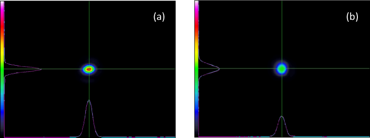
Before measuring the LEP beam intensity, we tested the cylindrical expander by monitoring the beam shape with a beam profiler, made of a CMOS pixel sensor (‘LaserCam-HR-UV’ produced by Coherent Inc.). Just because of space limitation, the UV laser light from the 8 W ‘Paladin’ was focused at 10 m downstream of the beam expander by extracting the beam with extra mirrors and attenuating the power with beamsplitters. Figure 8(a) and (b) show the measured profiles of laser powers with and without mounting the cylindrical expander on the 80 expander, respectively. Gaussian fits to the vertical and horizontal profiles, which are shown in the left and lower sides of the figures, resulted in the 1/e2 diameters as listed in Table 7. The production of an elliptical beam shape was confirmed with the reduction of a vertical diameter. As shown in Table 7, peak power densities were also measured by the beam profiler in the two cases. By using the cylindrical expander, we observed a gain in the power density by a factor of 1.81, which was close to the expected value of two.
From this result, the backscattering rate of laser photons must increase nearly twice at the focus point. Simultaneously, the Rayleigh range or the effective range for the laser-electron collisions becomes shorter by reducing the beam waist size. Therefore, we plan the next tests to extend the Rayleigh range with a slight reduction of the peak power density by using a technique of a long range non-diffractive beam (LRNB) [18].
| Setup | w/ cylindrical | only using 80 |
|---|---|---|
| expander | expander | |
| Peak power density [W/cm2] | 1.072 | 0.591 |
| Horizontal diameter [mm] | 0.181 | 0.182 |
| Vertical diameter [mm] | 0.127 | 0.194 |
4.3 Simulation Results and Prospects for the New Beamline at SPring-8
Higher intensity LEP beams using the methods developed in the present article is being produced at a new beamline of SPring-8 for the purpose to advance the next generation hadron experiments, called LEPS2. The construction of the LEPS2 beamline has started from 2010 at a 30 m-long straight section (BL31LEP), where a horizontal divergence of the electron beam is significantly reduced to 12 rad. Since the produced LEP beam must be narrow enough even after a long propagation, a large spectrometer system, covering 4 solid angles with a 1 Tesla solenoidal magnet, is under construction at a 135 m-downstream open space outside the storage ring building. A large acceptance electromagnetic calorimeter system, called BGOegg, is also prepared beside the charged spectrometer. At this new beamline, it is aimed to increase the LEP intensity by about an order of magnitude for both the cases of injecting UV and DUV laser light. Simultaneous injection of four laser beams are intended by enlarging the apertures of beamline chambers.
The four-laser injection is being achieved by preparing two sets of two-laser injection systems, described in Sections 2.3 and 3.3. Two prisms, which individually merge two laser beams, are set up with a height difference to avoid the interference of beam paths. We have designed to inject the merged beams from a side-wall of the storage ring tunnel in order to reduce the distance to a collision point. This way of laser injection minimizes the apertures of beamline chambers, where an ultrahigh vacuum is necessary. A radiation shield hutch surrounding the laser system is also needless because the lasers are no more placed in the direction of synchrotron radiation. Four ‘Paladin’ lasers and four ‘Frequad-HP’ lasers will be separately installed with the injection optics, which are optimized for the individual wavelengths, inside a clean room. Higher power lasers, including the newest type of ‘Paladin’ with an output power of 24 W, are also being introduced.
Figure 9 shows the estimation of LEP intensity gains by using the 8 W ‘Paladin’ lasers at the LEPS2 beamline in comparison with the case of the single-laser injection using the same ‘Paladin’ at the LEPS beamline. Closed circles, open diamonds, and open squares indicate the relative gains depending on the 2 (1/e2) radius of a laser beam waist in the cases of four-, two-, and single-laser injection, respectively. Here the ideal propagation of a Gaussian beam was simulated in the way similar to that in Section 3.3. A focal length of the laser light is reduced to 31.5 m at the LEPS2 beamline, and the collision range at the straight section is increased to about 10 m, which is determined from a constraint by the position of a laser monitor chamber. A transverse position of the expander output center was scanned on a 1 mm matrix grid to search for the best injection angle with the maximum gain, and the obtained maximum gain factors were plotted in Fig. 9. The area outside the reflection planes of prisms was cut off from the numerical integration of power densities. The 1/e2 radii of an electron beam at the long straight section are 0.64 mm and 0.024 mm in the horizontal and vertical directions, respectively, so that the LEP beam intensity by single-laser injection is maximized at an average of these sizes. In contrast, the intensity by four-laser injection most increases at a larger waist size because of a finite injection angle. The maximum gain factor with four lasers is estimated to be 2.14.

Although the simulation result is obtained by assuming the use of the 8 W ‘Paladin’, we actually operate the 16 W and 24 W types. We also plan to use the DUV lasers with an increased power near future. Thus, an extra factor of two or more must be multiplied to the estimated gain factor of 2.14. In addition, the optical handling of a laser cross section is under considerations as discussed in Section 4.2. Moreover, an aluminum-coated silicon mirror, which guides the injected laser light to the straight section, is modified to have a thin horizontal slit for avoiding X-ray irradiation and a small hole for the LEP beam path. This reduces the total amount of e+e- conversions during the LEP beam transportation to the experimental site, resulting in the further gain of the transported beam intensity by a factor of 1.12. Such a mirror modification is possible only in the case of injecting four lasers.
The construction of the LEPS2 beamline has just finished in the end of 2012. We have observed the first LEP beam with single-laser injection in the beginning of 2013. Optimizations for injection setups and intensity monitors have not been completed yet. Detail descriptions and beam upgrade results for the LEPS2 beamline will be discussed by a separate article. Experiments by the BGOegg detector will start in 2013, and the spectrometer system is being prepared in parallel. Physics results with higher precision and larger kinematical coverage, compared with the LEPS experiments, will appear in the near future to obtain new insights of hadron natures.
5 Summary
At the SPring-8 LEPS beamline, we developed the methods to upgrade the high energy LEP beam, which was produced by the backward Compton scattering of laser light from 7.975 GeV electrons. An all-solid UV laser with a wavelength of 355 nm was introduced because of the advantage of low power consumption. In spite of the 80 MHz pulsed emission, the output power of 8 W has successfully resulted in the LEP beam intensity of 1–2106 sec-1 in the tagged energy range of 1.5–2.4 GeV. There is large variation of the measured intensity because the transmission rate at laser injection optics drops with a life of 312.88 days by the accumulation of radiation exposure. Thanks to the low power consumption, we performed the simultaneous injection of two UV laser beams by merging them with a right-angle prism. We confirmed an acceptance-corrected intensity gain by a factor of 1.6, which is reduced from two due to small finite injection angles. The UV output power of the solid-state laser has been improved up to 16 W or 24 W. We observed that the LEP beam intensity was nearly doubled by using the 16 W laser.
The maximum energy of a LEP beam has been also extended by introducing DUV lasers. We measured its energy spectrum by detecting recoil electrons at the tagger, and confirmed that the Compton edge was raised up to 2.89 GeV with a 266 nm laser as expected. Using the solid-state laser with an output power of 1 W, the LEP beam intensity has reached 0.1–0.2106 sec-1. Two DUV laser beams were simultaneously injected in the way similar to the UV case, resulting in the acceptance-corrected intensity gain by a factor of 1.8.
The developed methods have been adopted at the LEPS beamline for hadron photoproduction experiments. In addition, they are being utilized at the LEPS2 beamline, whose construction has just finished at SPring-8 in the end of 2012. As a result of simulations, four-laser injection with the 24 W UV output powers increases the photon beam intensity at the LEPS2 beamline by a factor of 6.4 relative to the case of the single 8 W laser injection at the LEPS beamline. An additional gain will be obtained from the transformation of laser beam shapes. The tagged LEP intensity at 1.52.4 GeV must be close to 107 sec-1. Similarly, we expect a higher intensity approaching 106 sec-1 for the injection of DUV laser beams. The laser mirror modification with a center hole for the LEP beam path has a further effect to increase both the beam intensities at the experimental site by a factor of 1.12. Our developments would be applicable to other facilities to generate a laser-Compton backscattering beam.
We thank to the support of the staff at SPring-8 for giving excellent experimental conditions. This research was supported in part by the Ministry of Education, Science, Sports and Culture of Japan.
References
- [1] R.H. Milburn, Phys. Rev. Lett. 10 (1963) 75.
- [2] F.R. Arutyunyan and V.A. Tumanian, Phys. Lett. 4 (1963) 176.
- [3] N. Muramatsu, arXiv:1201.4094 (2012).
- [4] A. D’Angelo et al., Nucl. Instr. and Meth. A 455 (2000) 1.
- [5] H. Ohgaki et al., Nucl. Instr. and Meth. A 455 (2000) 54.
- [6] K. Aoki et al., Nucl. Instr. and Meth. A 516 (2004) 228.
- [7] K. Kawase et al., Nucl. Instr. and Meth. A 592 (2008) 154.
- [8] W. Guo et al., Nucl. Instr. and Meth. A 578 (2007) 457.
- [9] J.K. Ahn and E.S. Kim, Nucl. Instr. and Meth. A 528 (2008) 600.
- [10] http://www.spring8.or.jp/.
- [11] T. Nakano et al., Nucl. Phys. A684 (2001) 71c.
- [12] T. Matsumura et al., Nucl. Instr. and Meth. A 582 (2007) 489.
- [13] W.P. Leung et al., Appl. Phys. Lett. 58 (1991) 551.
- [14] A.D. Rakić, Appl. Opt. 34 (1995) 4755.
- [15] S.H. Hwang et al., Phys. Rev. Lett. 108 (2012) 092001.
- [16] N. Muramatsu, Few-Body Syst. (2013), DOI:10.1007/s00601-013-0614-4.
- [17] Y. Kato, Few-Body Syst. (2013), DOI:10.1007/s00601-013-0681-6.
- [18] T. Aruga, Appl. Opt. 36 (1997) 3762.