The Detector System for the Stratospheric Kinetic Inductance Polarimeter (Skip)
Abstract
The Stratospheric Kinetic Inductance Polarimeter (Skip) is a proposed balloon-borne experiment designed to study the cosmic microwave background, the cosmic infrared background and Galactic dust emission by observing 1133 square degrees of sky in the Northern Hemisphere with launches from Kiruna, Sweden. The instrument contains 2317 single-polarization, horn-coupled, aluminum lumped-element kinetic inductance detectors (Lekids). The Lekids will be maintained at 100 mK with an adiabatic demagnetization refrigerator. The polarimeter operates in two configurations, one sensitive to a spectral band centered on 150 GHz and the other sensitive to 260 and 350 GHz bands. The detector readout system is based on the ROACH-1 board, and the detectors will be biased below 300 MHz. The detector array is fed by an F/2.4 crossed-Dragone telescope with a 500 mm aperture yielding a 15 arcmin FWHM beam at 150 GHz. To minimize detector loading and maximize sensitivity, the entire optical system will be cooled to 1 K. Linearly polarized sky signals will be modulated with a metal-mesh half-wave plate that is mounted at the telescope aperture and rotated by a superconducting magnetic bearing. The observation program consists of at least two, five-day flights beginning with the 150 GHz observations.
| Instrument Configuration | Flight 1 | Flight 2 |
|---|---|---|
| Spectral Band Centers [GHz] | 150 | 267, 350 |
| Spectral Bandwidth [/] | 0.27 | 0.22, 0.30 |
| Number of Detectors | 2317 | 1655, 662 |
| Total Number of Detectors | 2317 | 2317 |
| Detector NET [K] | 58.4 | 149, 354 |
| Instrument NET [K] | 1.24 | 3.76, 14.1 |
| Aperture Diameter [mm] | 500 | 280 |
| F/# | 2.4 | 4.3 |
| Beam FWHM [arcmin] | 14.5 | 14.5, 11.3 |
| Total Sky Coverage [deg2] | 1133 | 1133 |
| Range | 10 to 1000 | 10 to 1000 |
| Flight Duration [days] | 5 | 5 |
| Time on CMB Patch [hours] | 102.7 | 102.7 |
| Duty Cycle [%] | 86 | 86 |
| T sensitivity per 1∘ pixel [K] | 0.069 | 0.21, 0.78 |
| Q sensitivity per 1∘ pixel [K] | 0.097 | 0.29, 1.1 |
| Minimum (99% confidence) | 0.02 | |

1 Introduction
The cosmic microwave background radiation (CMB) carries an image of the universe as it was 380,000 years after the Big Bang. Measurements of the angular intensity and polarization anisotropies in the CMB have proven to be a treasure trove of cosmological information. For example, CMB measurements have helped reveal that spacetime is flat, the universe is 13.8 billion years old, and it is dominated by cold dark matter and dark energy. A faint and yet-to-be-detected divergence-free “B-mode” polarization anisotropy signal in the CMB should contain additional information; B-modes generated when CMB photons are gravitationally lensed by large-scale structure will yield the values of physical parameters such as the sum of the neutrino masses, and if discovered, an inflationary gravity-wave (IGW) B-mode signal would reveal the energy scale at which inflation occurred[1]. Skip is a proposed balloon-borne experiment designed with the sky coverage, angular resolution, sensitivity and spectral coverage needed to either measure or constrain the amplitude of the IGW signal to approximately the foreground confusion limit set by the aforementioned gravitational lensing signal. The table in Figure 1 shows the experiment characteristics and the plot shows the forecasted CMB power spectra results that will come from Skip.
To isolate the faint B-mode signals, brighter foreground signals, such as Galactic dust emission, must be precisely measured and removed from the CMB maps. To disentangle the various sky signals, Skip will observe a low-dust region in the Northern Hemisphere with three spectral bands, and then fit a frequency-dependent parametric dust model to the data pixel-by-pixel using standard likelihood techniques[2]. The target sky patch is accessible with launches from Kiruna, Sweden.
Because the Galactic dust emission is so faint in the Skip patch, the 350 GHz spectral band will also be able to image angular fluctuations in the cosmic infrared background (CIB)[3]. The CIB was emitted by dust grains in distant galaxies, and it has a redshifted, dust-like frequency spectrum. The CIB probes the matter distribution on redshifts , rather than at like the CMB, so it can be used to constrain star formation history and dark matter distribution.
Finally, Skip will investigate whether lumped-element kinetic inductance detectors (Lekids) are a candidate detector technology for a future CMB satellite mission. The Skip instrument is described in Section 2, the detector system is described in Section 3, and the observation program is described in Section 4.

2 Instrument Details
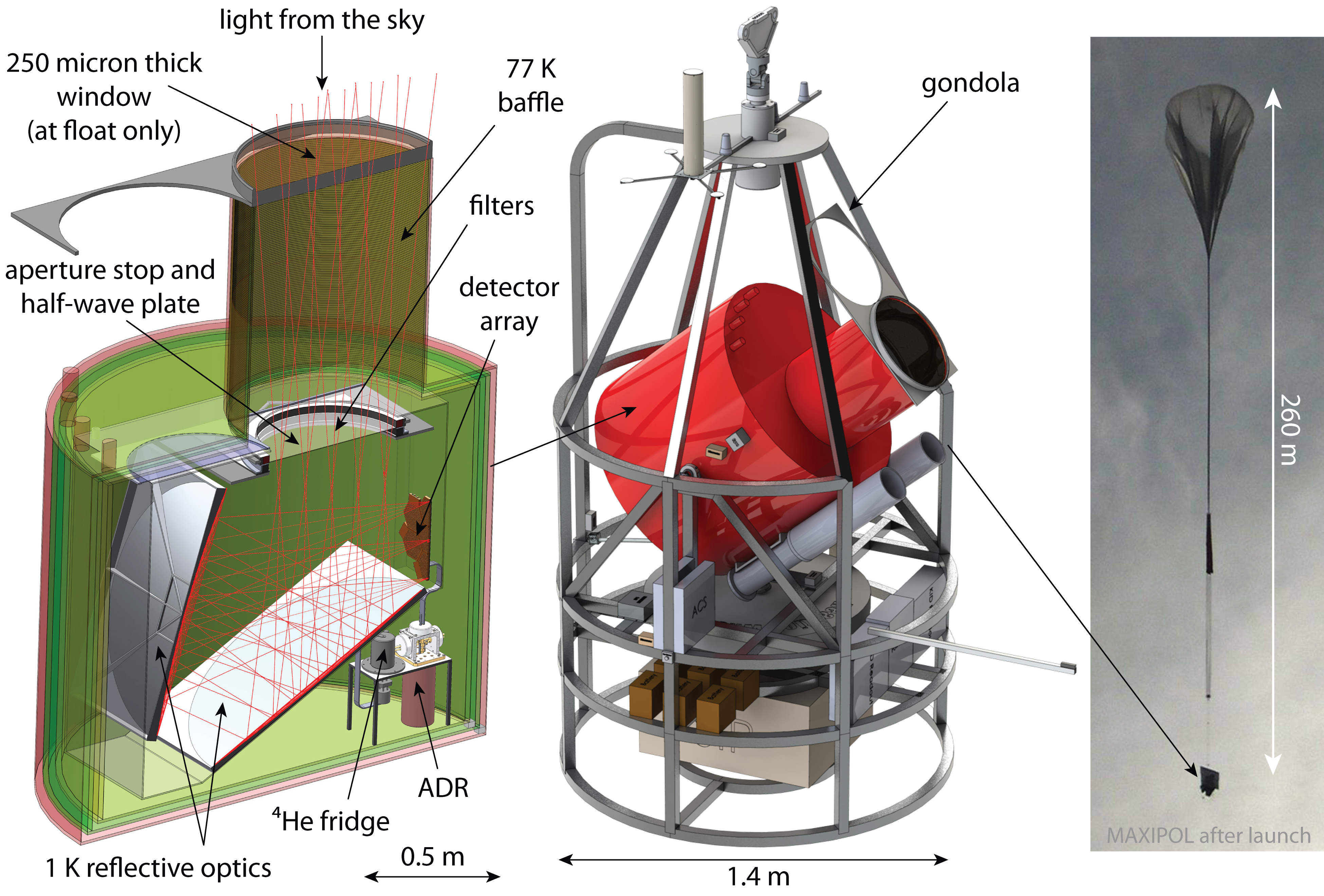
The Skip polarimeter is based on a catoptric crossed-Dragone telescope composed of an off-axis parabolic primary mirror and a hyperbolic secondary mirror yielding an effective focal length of 1200 mm (see Figure 2). A 500 mm diameter aperture stop, that is cooled to 1 K, produces a 15 arcmin FWHM beam at 150 GHz. A metal-mesh half-wave plate (HWP) mounted at this aperture stop will rotate at 7.4 Hz using a drive system based on a superconducting magnetic bearing (SMB), which minimizes vibrations and eliminates heating from stick-slip friction. When paired with the downstream analyzer, which is part of the detector array, the linearly polarized component of the sky signals will be modulated at four times the rotation frequency of the HWP in the data stream (29.7 Hz). The detector array, which contains 2317 single-polarization, horn-coupled, aluminum Lekids, is mounted at the focal plane of the telescope.
To minimize detector loading and maximize sensitivity, the entire polarimeter will be mounted inside a cryostat with liquid nitrogen and liquid helium stages. A box enclosing the optics will be thermally isolated from the liquid helium stage of this cryostat by Vespel legs and maintained at 1 K using a Chase Cryogenics closed-cycle 4He refrigerator, which is capable of providing 500 W of cooling power for five days. The detector array is mounted inside this 1 K optics box using thermally insulating Vespel legs, and it is cooled to 100 mK by a two-stage adiabatic demagnetization refrigerator (ADR). The ADR contains a ferric ammonium alum (FAA) paramagnetic salt pill with a 0.12 J capacity when regulated at 100 mK, backed by a gallium gadolinium garnet (GGG) salt pill with a 1.2 J capacity capable of cooling to 800 mK. Optical loading is controlled by (i) a radiation shield in the “snout” of the receiver held at 77 K, which is designed to control far side-lobes, (ii) a second radiation shield held at the liquid helium bath temperature ( K, see below) designed to terminate power from the horns down to -20 dB, (iii) a series of low-pass metal-mesh filters that reject high-frequency radiative power from the sky, and (iv) the receiver uses a double window mechanism based on designs that have flown successfully in the past[5, 6] in which a retractable thick window supports the differential pressure between the inside and outside of the cryostat on the ground, while a thin (250 m) window is revealed at float. The polarimeter operates in two configurations, one sensitive to a single spectral band centered on 150 GHz and the other sensitive to 260 and 350 GHz bands. The only differences between configurations are (i) the band-defining filters, (ii) the single-moded waveguide section of the horn, (iii) the aperture stop diameter, and (iv) the half-wave plate.
The polarimeter is housed in a robust gondola designed for multiple flights. The balloon and the instrument will reach an altitude of 100-125 kft, where the ambient pressure is 5-13 mbar. We regulate the nitrogen vapor to atmospheric pressure and allow the helium bath to reach ambient pressure at float, resulting in a nitrogen stage temperature of 77 K and a helium stage temperature of approximately 1.5 K.

3 Lekid Detector System
The Skip focal plane architecture is shown in Figure 3. The focal plane diameter is mm, and it consists of seven hexagonal modules. Each module contains 331 horn-coupled Lekids, for a total of 2317 detectors. All of the detectors in a single module are frequency-multiplexed in a 135–270 MHz readout band, allowing the entire focal plane to be read out using only seven SiGe bipolar cryogenic low noise amplifiers (LNAs)[7] and seven pairs of coaxial cables.
We use horns to couple sky signals to the detectors. As shown in Figure 3b, the horn narrows down to a single-mode rectangular waveguide section, which reduces spillover and stray-light loading inside the optics box and provides high-performance polarization selection and an integrated high-pass filter. The mm horn aperture allows a dense focal plane layout and yields high receiver sensitivity and fast mapping speeds. With this relatively small horn aperture, the instrument beam is primarily defined by the cold aperture stop. The horns couple with approximately 38% efficiency to the sky at 150 GHz, and the remaining 62% of the horn beam is terminated on the 1 K optics box which results in negligible loading. The final section of the waveguide is re-expanded to flatten the propagation impedance at the low-frequency edge of the band, which improves optical coupling and allows the radiation to be launched efficiently into the silicon Lekid wafer.
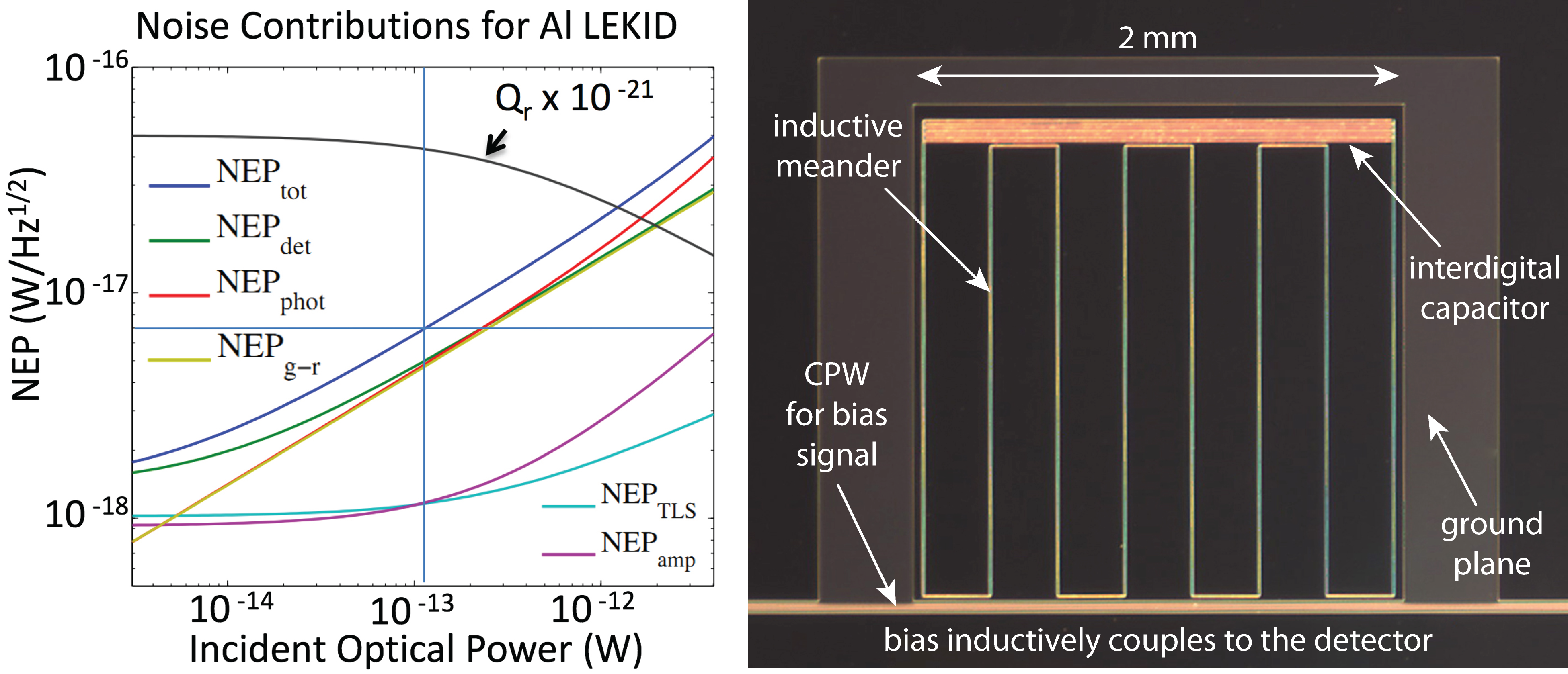
The Lekids will be fabricated from 20 nm thick aluminum films deposited on 300 m thick, high-resistivity silicon substrates. The baseline pixel design consists of a back-illuminated single-polarization Lekid where the inductor/absorber is a meandered aluminum trace on a silicon substrate with a filling factor designed to match the wave impedance (see Figure 4). This design is similar to the absorbers used in the NIKA[8] and MAKO[9] instruments. An anti-reflection coating (ARC) of fused quartz is used to impedance match the silicon wafer and the horn. The ARC and detector wafers are mounted directly to the back of the horn plate and a metal back plate closes each module. The back plate has metal cavities behind each detector that are designed to act as backshorts close to in length. The small fraction of the radiation that propagates laterally in the two dielectric substrates will be absorbed by a titanium nitride (TiN) film deposited and patterned on the ARC. This TiN layer has apertures in it to allow radiation from the sky to propagate from the horns through the quartz and silicon to the detectors.

The detector readout electronics are based on (i) the ROACH signal processing board, developed by the CASPER collaboration[13], which hosts a Xilinx field-programmable gate array (FPGA) and (ii) the successful Open-Source Readout system developed at Caltech for the MUSIC instrument[12]. The stimulus tones for the Lekid resonators are directly synthesized in the 135–-270 MHz band using a continuous playback ring-buffer which drives a 16-bit digital-to-analog converter (DAC). The output of the DAC is amplified and bandpass-filtered to suppress harmonics before being fed to the detector wafer. Digitally controlled attenuators are used to optimally adjust the overall signal levels. After exiting the cryostat, the modulated carrier tones are then further amplified and filtered before being sampled by a 12-bit analog-to-digital converter (ADC). The digitized data is then channelized by the same FPGA. The voltage data from 331 channels which contain resonators will then be sent via Ethernet to data acquisition computers for storage. Figure 5 shows an overview of the Skip data acquisition electronics.


4 Observation Plans
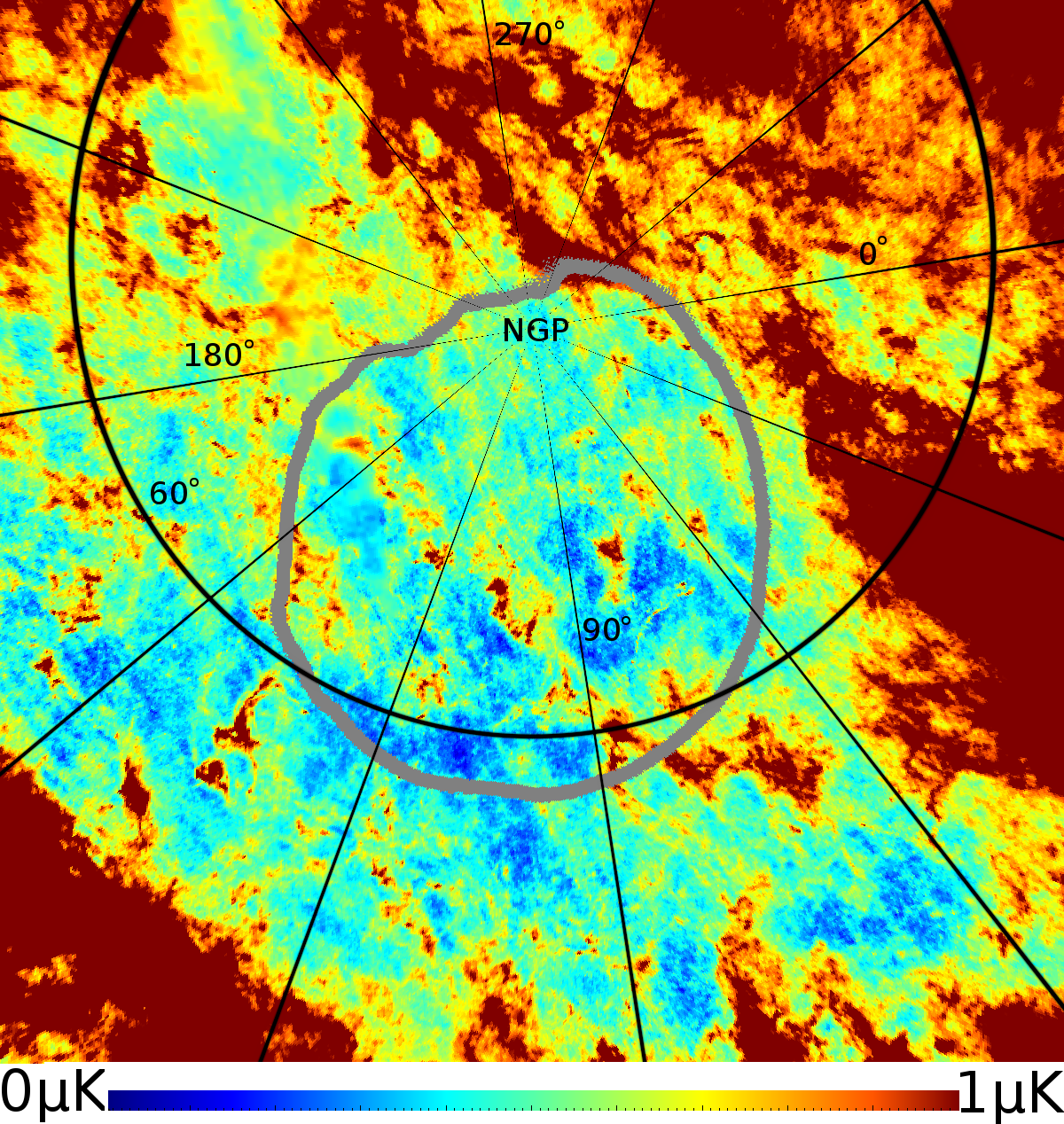
One of the lowest foreground regions at 150 GHz anywhere on the sky is located at Galactic coordinates (l, b) = (99∘, 75∘), which is in the Northern sky[4]. To observe this region, Skip will be launched from the ESRANGE balloon facility in Kiruna, Sweden (67.9∘ N, 20.2∘ E). A balloon flight from Kiruna allows five days of integration time, and this low-foreground target field can be continuously observed for the entire mission. The total time spent on the patch during a five-day flight is 103 hours, equivalent to an 86% observing efficiency, and the total sky coverage is 1133 deg2. The observation program consists of at least two, five-day flights. The first flight will use the 150 GHz configuration, while the second flight will use the 260 and 350 GHz configuration. Instrument recovery and relaunch can be done quickly with Kiruna flights, so two flights in two successive years are possible.


References
- [1] D. Baumann, et al., AIP Conference Series, 1141, 10, (2009).
- [2] H. K. Eriksen, J. B. Jewell, C. Dickinson, A. J. Banday, K. M. Gorski, and C. R. Lawrence, ApJ, 676, 10, (2008).
- [3] The Planck Collaboration. A&A submitted, (2013). arXiv:1309.0382
- [4] D. P. Finkbeiner, M. Davis, and D. J. Schlegel, ApJ, 524, 867, (1999).
- [5] S. T. Staggs, N. C. Jarosik, S. S. Meyer, and D. T. Wilkinson, ApJ, L1, (1996).
- [6] B. Reichborn-Kjennerud, et al., SPIE Conference Series, 7741, (2010).
- [7] J. C. Bardin and S. Weinreb, IEEE MWCL, 19, 6, 407, (2008).
- [8] A. Monfardini, et al., ApJS, 194, 24, (2011).
- [9] L. J. Swenson, et al., SPIE Conference Series, 8452, (2012).
- [10] J. Zmuidzinas, Annu. Rev. Condens. Matter Phys., 3, 169, (2012).
- [11] C. McKenney, JOLT submitted, (2013).
- [12] R. Duan, et al., SPIE Conference Series, 7741, (2010).
- [13] http://casper.berkeley.edu