GPU peer-to-peer techniques applied to a cluster interconnect
Abstract
Modern GPUs support special protocols to exchange data directly across the PCI Express bus. While these protocols could be used to reduce GPU data transmission times, basically by avoiding staging to host memory, they require specific hardware features which are not available on current generation network adapters. In this paper we describe the architectural modifications required to implement peer-to-peer access to NVIDIA Fermi- and Kepler-class GPUs on an FPGA-based cluster interconnect.
Besides, the current software implementation, which integrates this feature by minimally extending the RDMA programming model, is discussed, as well as some issues raised while employing it in a higher level API like MPI.
Finally, the current limits of the technique are studied by analyzing the performance improvements on low-level benchmarks and on two GPU-accelerated applications, showing when and how they seem to benefit from the GPU peer-to-peer method.
I Introduction
Thanks to their high computational power and high memory bandwidth, as well as to the availability of a complete programming environment, Graphics Processing Units (GPUs) have quickly risen in popularity and acceptance in the HPC world. The challenge is now demonstrating that they are suitable for capability computing, i.e. they are still effective when scaling on multi-node multi-GPU systems. Multi-GPU is needed to decrease time-to-solution (strong scaling), to match the requirements of modern demanding applications, e.g. by overcoming the GPU memory size limitations (bigger simulation volumes, finer grained meshes, etc.) or even to enable new types of computation which otherwise would not be possible.
In many cases, applications show poor scaling properties because, on increasing the number of computing elements, the computation locally performed by processing nodes shrinks faster than the amount of communication. To fix it, a well-established optimization technique is overlapping computation and communication. Additionally, due to staging of GPU data in host buffers prior and/or after the communication phase, network exchange of large buffers typically needs a proper coding (pipelining) to obtain good bandwidth. These two techniques are inter-related: staging, when not properly implemented, can hurt overlapping due to unexpected synchronizations of GPU kernels; on the other hand, staging data, while computing is underway, is essential to obtain the overlap.
The use of the peer-to-peer exchange of data among multiple GPUs in a single box, instead of using a simple intra-node message-passing approach, is reported to provide a 50% performance gain on capability problems, as for example recently discussed in the literature [1]. In principle, the same peer-to-peer technology, applied to an interconnection network, can also be employed to enable remote transfers of GPU buffers without staging to host memory. Anyway, a few capabilities are required to do so efficiently, at least on NVIDIA Fermi-class GPUs, which are beyond those available in current commercial cluster interconnects (InfiniBand, 10G). Those capabilities, if cost effective, will probably appear in next generation silicon devices with the typical delay due to VLSI design and production cycles (18-24 months).
In the meantime, it is entirely possible to experiment with GPU peer-to-peer networking by using reconfigurable components, like the Altera Statix IV in the APEnet+ card [2], which offers both high-performance specialized transmission logic blocks and high-capacity on-chip memory banks.
In this paper we report on our experiences in adding GPU peer-to-peer capabilities to the APEnet+ network interconnection, presenting some early performance results.
The paper is organized as follows: in section II we cite some related works; section III briefly introduces the GPU peer-to-peer technology and the APEnet+ network adapter, while section IV describes the implementation issues related to how the technology has been introduced in APEnet+; section V contains the preliminary results obtained on APEnet+, in particular on synthetic benchmarks and on two multi-GPU applications; the last section contains conclusions and some final remarks.
II Related works
Previous attempts at integrating GPUs with network interconnect middlewares, although showing interesting results, all fall in the software-only category.
While early attempts at integrating GPU-awareness with MPI date back to 2009 [3], two of the most widely used MPI implementations, OpenMPI [4] and MVAPICH2 [5], have recently started to offer the possibility of specifying GPU memory pointers in MPI point-to-point functions, suppressing the chore of explicitly coding the data transfers between GPU and CPU memories. This feature represents an essential part of the research efforts aimed towards the definition of a general mechanism for direct communication among GPUs. Despite that, both OpenMPI and MVAPICH2 rely on a software approach which eases programming and that can increase communication performance for mid-to-large-size messages, thanks to pipelining implemented at the MPI library level. On the other hand, this approach can even hurt performance [6] for medium-size messages, due to them not using independent CUDA STREAMs, thereby introducing an implicit synchronization that ruins the computation-communication overlap in applications.
On a related note, MPI-ACC [7] experimented with alternative approaches at integrating GPUs with MPI, even discovering unexpected slow-downs and bugs in previous CUDA releases.
III Background
Fermi is the first NVIDIA GPU architecture which externally exposes a proprietary HW-based protocol to exchange data among GPUs directly across the PCI Express bus (PCIe), a technique which is generically referred to as peer-to-peer, and publicly advertised under the GPUDirect Peer-to-peer moniker.
The NVIDIA peer-to-peer protocol comprises a number of hardware resources (registers, mailboxes) implemented on the GPU and set of rules to use them. This protocol basically allows one GPU to read and write the memory of another GPU, provided that they are on a compliant platform (suitable PCIe bus topology, bug-free chipsets). At the API level, it is used by the cudaMemcpyPeer() and cudaMemcpyPeerAsync() APIs, or simply by cudaMemcpy() on selected platforms (UVA mode), when memory pointers refers to device memory residing on two different GPUs. This protocol can be used by a third-party device to gain direct access to the GPU memory, provided that it is able to consistently mimic the correct hardware behaviour and that the right bindings to the NVIDIA kernel driver are established at the software level. Since CUDA 4.1, the SW support to GPU peer-to-peer has been shipped as an internal preview technology, subject to NDA.
Beyond the peer-to-peer protocol, there is an additional access method for third-party devices, the so called BAR1. This methods is alternative to the peer-to-peer, and CUDA 5.0 has officially introduced a public API to support it on Kepler-based Tesla and Quadro GPUs. With BAR1, it is possible to expose, or map, i.e. to make it available, a region of device memory on the second PCIe memory-mapped address space of the GPU, from which it can be read or written with standard PCIe memory operations. Due to platform constraints (32-bits BIOS), this address space is limited to a few hundreds of megabytes, so it is a scarce resource. Additionally, mapping a GPU memory buffer is an expensive operation, which require a full reconfiguration of the GPU. As it is shown below, the BAR1 reading bandwidth on Fermi is quite limited, suggesting that the Fermi architecture was not optimized for this access method. That is why we have never used the BAR1 method on Fermi.
APEnet+ has been supporting peer-to-peer on Fermi since the end of 2011, and since recently also BAR1 and peer-to-peer on Kepler.
III-A GPU peer-to-peer technology
In CUDA, the peer-to-peer/BAR1 support for third-party device is split into a user- and a kernel-space part. The user-space function cuPointerGetAttribute() with the CU_POINTER_ATTRIBUTE_P2P_TOKENS parameter is used to retrieve special handles from pointers to GPU memory buffers. Those handles are then used in kernel-space to properly map the GPU buffers, i.e. one page descriptor for each 64 KB page, comprising the physical page address plus additional low-level protocol tokens which are used to physically read and write GPU memory.
Technically, peer-to-peer writing of GPU memory is only slightly more difficult than host memory writing, the only difference being the managing of a sliding window to access different pages. GPU memory reading is instead more complex because it is designed around a two-way protocol between the initiator and the target devices. This design is justified by the need to work around bugs in PCIe chip-sets, related to a traffic pattern among devices which is still quite uncommon at least on the x86 platform. The ability to use the peer-to-peer protocol among GPUs, and its performance, is constrained by the PCIe topology; performance is excellent when two GPUs share the same PCIe root-complex, e.g. they are directly connected to a PCIe switch or to the same hub. Otherwise, when GPUs are linked to different bus branches, performance may suffers or malfunctionings can arise. This can be an issue on multi-socket Sandy Bridge Xeon platforms, where PCIe slots might be connected to different processors, therefore requiring GPU peer-to-peer traffic to cross the inter-socket QPI channel(s).
III-B APEnet+
APEnet is a 3D Torus interconnection technology originally proposed, in its first version, back in 2004 [8] and which is now being developed in its second generation version, called APEnet+ [9]. It has a direct network design which combines the two traditional components: the Network Interface (NI) and the Router (RTR). The Router implements a dimension-ordered static routing algorithm and directly controls an 8-ports switch, with 6 ports connecting the external torus link blocks (, , , , , ) and 2 local packet injection/extraction ports. The APEnet+ Network Interface comprises the PCIe X8 Gen2 link to the host system, for a maximum data transfer rate of 4+4 GB/s, the packet injection logic (TX) with a 32 KB transmission buffer, and the RX RDMA logic which converts the virtual memory address of the destination buffer into a scatter list of physical memory addresses. The core architecture is depicted on Fig 1.
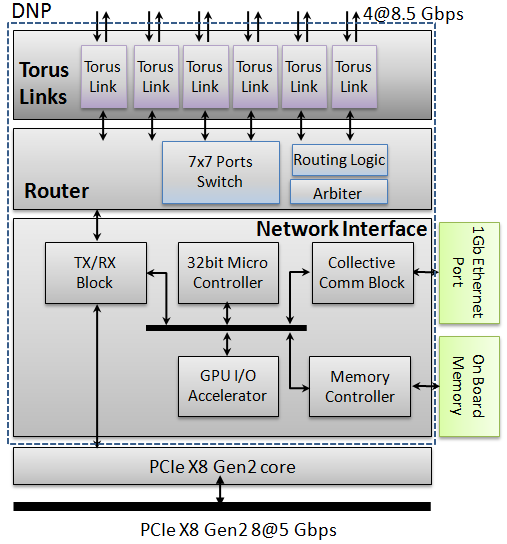
The receiving (RX) data path manages buffer validation (the BUF_LIST) and virtual-to-physical address translation (the HOST_V2P map); these tasks are currently partly implemented in software running on a micro-controller (Nios II), which is synthesized onto the Stratix IV FPGA. On the transmit (TX) data path, equivalent tasks are carried on by the kernel device driver, which implements the message fragmentation and pushes transaction descriptors with validated and translated physical memory addresses.
The APEnet+ architecture is designed around a simple Remote Direct Memory Access (RDMA) programming model. The model has been extended with the ability to read and write the GPU private memory — global device memory in CUDA wording — directly over the PCIe bus, by exploiting the NVIDIA GPUDirect peer-to-peer (P2P) HW protocol.
IV Implementing GPU peer-to-peer technology on APEnet+
APEnet+ is relatively easy to extend thanks to the presence of the reconfigurable hardware component (an Altera FPGA) which, among other resources like transceiver blocks, memory banks, etc., provides a 32 bit micro-controller (Nios II) that can run up to 200 MHz and is easily programmable in C.
Introducing GPU peer-to-peer in APEnet+ has been relatively easy for the receive data path, in that the 64 KB page GPU windowing access has been implemented as a variation of the 4 KB page host memory writing flow. Either the relevant data structures have been extended (the BUF_LIST) to accept both host and GPU buffers, or new ones have been added (the new GPU_V2P map, one per GPU).
For both read and write, physical GPU memory addresses are needed to generate the transactions on the PCIe link, so a proper GPU virtual-to-physical address translation module, GPU_V2P, has been implemented on APEnet+, very similar to but not exactly the same as the host one. For each GPU card on the bus, a 4-level GPU_V2P page table is maintained, which resolves virtual addresses to GPU page descriptors.
Currently, the processing time of an incoming GPU data packet is of the order of 3 s (1.2 GB/s for 4 KB packets) and it is equally dominated by the two main tasks running on the Nios II: the BUF_LIST traversal (which linearly scales with the number of registered buffers) and the address translation (which has constant traversal time thanks to the 4-level page table).
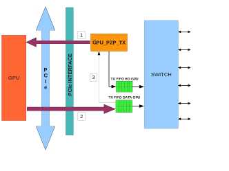
Good performance in GPU memory reading, which is used during transmission of GPU buffers, has instead been by far the most difficult task to achieve, requiring two major redesigns of the related SW/HW blocks. Unlike host buffer transmission, which is completely handled by the kernel driver, GPU data transmission is delegated to the APEnet+. This is so not only to off-load the host, which would be a minor requirement, but mainly for the architectural need of maintaining the correct data flow among the different actors involved: the multiple-outstanding read request queue of the GPU (arrow 1 in fig. 2), the data flow (arrow 2) insisting on the APEnet+ data transmission buffers and the outgoing channel buffers. This flow needs proper management to avoid buffer overflowing but at the same time it has to be carefully tuned to obtain enough performances. With the first generation GPU memory reading and control flow logic (GPU_P2P_TX) (V1), which was able to process a single packet request of up to 4KB, the peak GPU reading bandwidth [2] was throttled to 600 MB/s. The reasons for the poor performances were: the slow rate of read requests emitted by the GPU_P2P_TX block towards the GPU and the long latency of the GPU in responding with data, which is quite understandable as the GPU memory subsystem is optimized for throughput rather than for latency. Besides, the GPU_P2P_TX was impacting the RX processing path due to the high computation load on the Nios II micro-controller.
The second generation GPU_P2P_TX implements two key improvements: an hardware acceleration block which generates the read requests towards the GPU with a steady rate of one every 80 ns; a pre-fetch logic which attempts to hide the response latency of the GPU. Additionally, thanks to the acceleration blocks, the Nios II micro-controller can allot a larger time-slice to the receive data path (RX processing). By using a 32 KB prefetch window, which is related to the size of the transmission buffers (TX FIFO), the GPU_P2P_TX was able to reach the current peak of 1.5 GB/s for the GPU reading bandwidth.
In the last generation GPU_P2P_TX (V3), the new flow-control block is able to pre-fetch an unlimited amount of data so as to keep the GPU read request queue full, while at the same time back-reacting to almost-full conditions (arrow 3 in fig. 2) of the different on-board temporary buffers (TX Data FIFO, TX Header FIFO, peer-to-peer REQUEST FIFO, etc.).
Fig. 5 and 5 show the effect of the different GPU_P2P_TX implementations onto the GPU reading bandwidth and on the whole loop-back bandwidth.
IV-A Changes to RDMA API for GPUs
The APEnet+ APIs have been extended to handle transmission and reception of GPU buffers, in a way that makes extensive use of the Uniform Virtual Address (UVA) capability of CUDA. With UVA — available on most 64-bits platforms and OS’s, — GPU buffers are assigned unique 64-bits addresses, and they can be distinguished from plain host memory pointers by using the cuPointerGetAttribute() call, which also returns other important buffer properties like the GPU index and the CUDA context.
The APEnet+ buffer pinning and registration API now accepts GPU buffers, which are mapped on-the-fly if not already present in an internal cache. Buffer mapping consists in retrieving the peer-to-peer informations, then passing them down to the kernel driver and from there to the Nios II micro-controller, in the BUF_LIST and GPU_V2P data structures. After registration, a buffer — either a host or GPU, uniquely identified by its (UVA) 64-bit virtual address and process ID — can be the target of a PUT operation coming from another node. Network packets carry the 64-bit destination virtual memory address in the header, so when they land onto the destination card, the BUF_LIST is used to distinguish GPU from host buffers.
On the transmitting node, the source memory buffer type is chosen at compilation time by passing a flag to the PUT API. This is useful to avoid a call to cuPointerGetAttribute(), which is possibly expensive [7], at least on early CUDA 4 releases. When a GPU buffer is transmitted, the buffer mapping is automatically done, if necessary, and a simplified descriptor list containing only GPU virtual addresses is generated by the kernel driver and passed to the Nios II micro-controller. As in the RX processing phase, the Nios II is once again in charge of the virtual-to-physical translation of source memory page addresses, in addition to driving the GPU peer-to-peer protocol together with the HW acceleration blocks.
V Benchmarking
In this section we report the results of GPU peer-to-peer enabled benchmarks and applications on APEnet+.
The APEnet+ test platform (Cluster I in the following) is made of eight dual-socket Xeon Westmere nodes, arranged in a torus topology, each one equipped with a single GPU (all Fermi 2050 but one 2070) and a Mellanox ConnectX-2 board, plugged in a PCIe X4 slot (due to motherboard constraints) and connected to a Mellanox MTS3600 switch.
Infiniband results were collected on a second 12-nodes Xeon Westmere cluster (Cluster II), each node equipped with two Fermi 2075 GPUs (Tesla S2075) and a Mellanox ConnectX-2 board, plugged in a PCIe X8 slot and connected to a Mellanox IS5030 switch.
ECC is off on both clusters. MVAPICH2 1.9a2 and OSU Micro Benchmarks v3.6 were used for all MPI IB tests.
V-A PCIe bus analysis
The successive revisions of the APEnet+ peer-to-peer support has been guided by a low-level analysis of the performance on the PCIe bus, through the use of a bus analyzer.
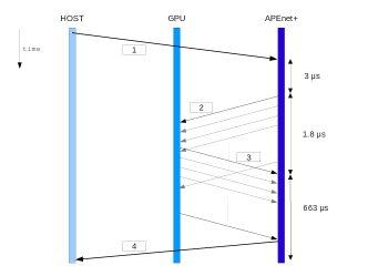
In fig. 3, we report the timings of the most important PCIe bus transactions, as seen by an active interposer sitting between the APEnet+ card and the motherboard slot. The most interesting informations are: the APEnet+ GPU_P2P_TX (v2, in this case) implementation has an overhead which is a substantial part of those 3 s in the initial delay (transaction 1 to 2). That overhead partially overlaps with previous transmissions, so it is paid in full either at the beginning of a long communication phase (with minor effects) or on short-message round-trip tests (with visible effects on the network latency).
The head reading latency of GPU is 1.8 s (transaction 2 to 3), then it sustains a 1536 MB/s data throughput towards APEnet+ transmission buffers (transaction 3 to 4 is 663 s for a single 1 MB message, 53% link utilization). The read requests generated towards the GPU by the GPU_P2P_TX hardware accelerator are regularly emitted once every 76 s, i.e. 96 MB/s of protocol traffic and 13% link utilization.
As of the peer-to-peer write bandwidth, judging from PCIe bus traces, the GPU has no problem sustaining the PCIe X8 Gen2 traffic, even though APEnet+ is currently not able to use all the available bandwidth due to limitations of its RX packet processing (more on this below).
V-B Single-node benchmarks
To give an idea of the performance and limitations of the current implementation, in table I we collected the memory read performance, as measured by the APEnet+ device, for buffers located on either host or GPU memory.
| Test | Bandwidth | GPU/method | Nios II active tasks |
|---|---|---|---|
| Host mem read | 2.4 GB/s | none | |
| GPU mem read | 1.5 GB/s | Fermi/P2P | GPU_P2P_TX |
| GPU mem read | 150 MB/s | Fermi/BAR1 | GPU_P2P_TX |
| GPU mem read | 1.6 GB/s | Kepler/P2P | GPU_P2P_TX |
| GPU mem read | 1.6 GB/s | Kepler/BAR1 | GPU_P2P_TX |
| GPU-to-GPU loop-back | 1.1 GB/s | Fermi/P2P | GPU_P2P_TX + RX |
| Host-to-Host loop-back | 1.2 GB/s | RX |
As discussed in the previous section, the complexity of the GPU peer-to-peer read protocol and the limitations of our implementation set a limit of 1.5 GB/s to the Fermi GPU memory read bandwidth, which is roughly half that obtained for host memory read (2.4 GB/s). For reference, the GPU-to-host reading bandwidth, as obtained by cudaMemcpy, which uses the GPU DMA engines, peaks at about 5.5 GB/s on the same platform. We also report very early results on Kepler GPUs, for both K10 and K20, which show a 10% increase in the available peer-to-peer reading bandwidth with respect to Fermi in P2P mode, and a more impressive factor 10 using the BAR1 approach (150 MB/s on Fermi vs. 1.6 GB/s on K20). Tests on Kepler GPUs have been run on pre-release cards, so the reported performance is subject to change.
We underline that this is the reading bandwidth as measured from APEnet+ through the GPU peer-to-peer protocol, neither the internal device bandwidth, which is instead available to kernels running on the GPU, nor the GPU DMA engine bandwidth, e.g. cudaMemcpy().
The last two lines of table I show that, when the packet RX processing is taken into account by doing a loop-back test, the peak bandwidth decreases from 2.4 GB/s to 1.2 GB/s in the host-to-host case, and from 1.5 GB/s to 1.1 GB/s in the GPU-to-GPU case, i.e. an additional 10% price to pay in the latter case. The last column in the table shows that the Nios II micro-controller is the main performance bottleneck. We are currently working on adding more hardware blocks to accelerate the RX task.
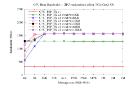
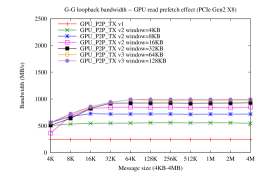
The values reported in table I are obtained as the peak values in a loop-back performance test, coded against the APEnet+ RDMA API. The test allocates a singe receive buffer (host or GPU), then it enters a tight loop, enqueuing as many RDMA PUT as possible as to keep the transmission queue constantly full. Fig. 5 is a plot of GPU reading bandwidth at varying message sizes, estimated by using the test above and by flushing TX injection FIFOs, effectively simulating a zero-latency infinitely fast switch. The original GPU_P2P_TX v1 implementation (no pre-fetching and software-only implementation on Nios II) shows its limits. GPU_P2P_TX v2 (HW acceleration of read requests and limited pre-fetching) shows a 20% improvement while increasing the pre-fetch window size from 4KB to 8KB. Unlimited pre-fetching and more sophisticated flow-control in GPU_P2P_TX v3 partially shows its potential only in the full loop-back plot of Fig. 5 Here the Nios II handles both the GPU_P2P_TX and the RX tasks, so therefore any processing time spared thanks to a more sophisticated GPU TX flow-control logic reflects to an higher bandwidth. This also suggests that the APEnet+ bi-directional bandwidth, which is not reported here, will reflect a similar behaviour.
V-C Two-nodes benchmarks
As shown above, reading bandwidth from GPU memory and RX processing are the two key limiting factors of the current APEnet+ implementation. Therefore, it can be expected that they influence the communication bandwidth between two nodes in different ways, depending of the type of the buffers used. To measure the effect of those factors independently, we run a two node bandwidth test on APEnet+, in principle similar to the MPI OSU [10] uni-directional bandwidth test, although this one is coded in terms of the APEnet RDMA APIs.
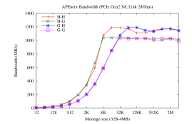
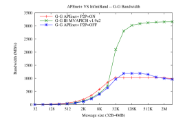
The plot in Fig. 7 shows the bandwidth of APEnet+ for the four different possible combinations of source and destination buffer types: for source buffers located in host memory, the best performance of 1.2 GB/s is reached, with a 10% penalty paid when receive buffers are on the GPU, probably related to the additional actions involved, i.e. switching GPU peer-to-peer window before writing to it. For GPU source buffers, the GPU peer-to-peer reading bandwidth is the limiting factor, so the curves are less steep and only for larger buffer sizes, i.e. beyond 32 KB, the plateau is reached. Clearly, the asymptotic bandwidth is limited by the RX processing, but the overall performance is affected by the transmission of GPU buffers. Interestingly, the Host-to-GPU performance seems to be a very good compromise bandwidth-wise, e.g. for 8 KB message size the bandwidth is twice that of the GPU-to-GPU case. Of course this plot is good for analyzing the quality of the APEnet+ implementation, but it says nothing about which method is the best for exchanging data between GPU buffers, i.e. in which ranges GPU peer-to-peer is better than staging on host memory. To this end, Fig. 7 is a plot of the GPU-to-GPU communication bandwidth, with three different methods: APEnet+ using GPU peer-to-peer; APEnet+ with staging of GPU data to host memory; OSU bandwidth test, using MVAPICH2 over Infiniband, which uses a pipelining protocol above a certain threshold, used for reference. The GPU peer-to-peer technique is definitively effective for small buffer sizes, i.e. up to 32 KB; after that limit, staging seems a better approach.
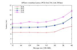
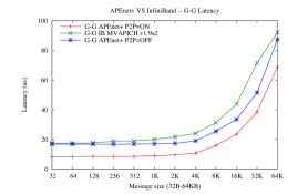
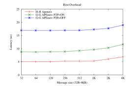
Fig. 10 is more useful to explore the behaviour of GPU peer-to-peer on small buffer size. Here the latency, estimated as half the round-trip time in a ping-pong test, shows a clear advantage of the peer-to-peer implementation with respect to staging (P2P=OFF in the figure), even on a very low-latency network as Infiniband. Indeed, the APEnet+ peer-to-peer latency is 8.2 s, while for APEnet+ with staging and MVAPICH2/IB it is respectively 16.8 s and 17.4 s. In the latter case, most of the additional latency comes from the overhead of the two CUDA memory copy (cudaMemcpy) calls necessary to move GPU data between temporary transmission buffers. By subtracting the APEnet+ H-H latency (6.3 s in Fig. 10) from the APEnet+ latency with staging (16.8 s), the single cudaMemcpy overhead can be estimated around 10 s, which was confirmed by doing simple CUDA tests on the same hosts.
The run times of the bandwidth test, for short message size, are plot in Fig. 10. In the LogP model [16], this is the host overhead, i.e. the fraction of the whole message send-to-receive time which does not overlap with subsequent transmissions. Of those 5 s in the host-to-host case, at least a fraction can be accounted to the RX processing time (3 s estimated by cycle counters on the Nios II firmware). The additional 3 s in the GPU-to-GPU (P2P=ON) case should be quite related to peer-to-peer protocol as implemented by APEnet+, e.g. the 3+1.8 s GPU_P2P_TX overhead in Fig. 3. When staging is used instead (P2P=OFF), out of the additional 12 s (17-5 s of the host-to-host case), at least 10 s are due to the cudaMemcpy device-to-host, which is fully synchronous with respect to the host, therefore it does not overlap.
In conclusion, the GPU peer-to-peer, as implemented in APEnet+, shows a bandwidth advantage for message sizes up to 32 KB. Beyond that threshold, at least on APEnet+ it is convenient to give up on peer-to-peer by switching to the staging approach. Eventually that could have been expected, as architecturally GPU peer-to-peer cannot provide any additional bandwidth, which is really constrained by the underling PCI-express link widths (X8 Gen2 for both APEnet+ and Infiniband) and bus topology.
V-D Over-relaxation in 3D Heisenberg Spin Glass
In this section we show an early evaluation of GPU peer-to-peer networking on a multi-GPU simulation code for the Heisenberg Spin Glass model [11, 1]. Thanks to its regular communication pattern, we consider it a good model application for typical lattice-based multi-GPU simulations. The GPU part of the code is highly optimized; it uses even-odd parallel update trick; the 3D domain is decomposed among the computing nodes along a single dimension, and the communication-computation overlap method is used: first compute the local lattice boundary, then exchange it with the remote nodes, while computing the bulk. The computation consists of multiple over-relaxation steps applied to the whole spin lattice of size :
| NP | |||
|---|---|---|---|
| 1 | 921 | 11 | n.a. |
| 2 | 416 | 108 | 97 |
| 4 | 202 | 119 | 113 |
| 8 | 148 | 148 | 141 |
In table II we collected the strong-scaling results on APEnet+ for the lattice size ; times are for single-spin update in picoseconds, the lower the better. As expected for the domain decomposition on a single dimension, the boundary calculation and network communication part is constant while the bulk computation part shrinks; we expect a good scaling up to eight nodes, when the two contribution become equal.
| Time | Cluster I |
Cluster II
OMPI (PCIe X8) |
Cluster I
OMPI (PCIe X4) |
||
|---|---|---|---|---|---|
| P2P=ON | P2P=RX | P2P=OFF | |||
| 416 | 416 | 416 | 416 | 416 | |
| 108 | 97 | 122 | 108 | 108 | |
| 97 | 91 | 114 | 101 | 101 | |
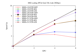
To better understand the contributions from computation and communication to the overall performance, in table III we collected the results on a two-nodes APEnet+ system: single spin update times are reported for 3 different combinations of use of GPU peer-to-peer. is the total compute time; refers to the boundary computation, carried out on an independent CUDA stream respect to the bulk computation; is the communication time alone. Interestingly, for and two nodes, the bulk computation is long enough to completely hide the boundary calculation and the communication. In this case, where for each computation the bulk of the communication consists of 6 outgoing and 6 incoming 128 KB messages, using the peer-to-peer for both TX and RX (P2P=ON) or only for RX (P2P=RX) respectively give a 14% and 20% advantage with respect to the staging approach (P2P=OFF). More generally, for , the spin lattice is small and comfortably fit in a single GPU, so it only scales up to 2 nodes. As seen above, scales well up to 4 nodes. At , it scales well up to eight nodes, and a super-linear speedup is observed, due to strong GPU cache effects. Indeed, in this case, the spin lattice is so big that it only fits in a single 2070 6 GB GPU (2050 has only 3 GB), though in this case with low efficiency (1471 ps for vs 921 ps for ). In this case, the P2P=RX case is 28% better than the staging case.
Acknowledging the fact that the results are subject to change on different platforms, for different choices of middleware and application parameters, we can anyway state that GPU peer-to-peer on APEnet+ is giving a 20-10% advantage over staging. This advantage could increase for a multi-dimensional domain-decomposition, where the size of the exchanged messages shrinks in the strong scaling, thanks to more regularly shaped 3D sub-domains.
V-E GPU-accelerated BFS traversal on distributed systems
Recent works [12][13] have shown that, by using a Level Synchronous BFS, a single-GPU implementation can exceed in performance high-end multi-core CPU systems. To overcome the GPU memory limitation, two of the authors (M.B., E.M) proposed [15] a multi-GPU code that is able to explore very large graphs (up to 8 billion edges) by using a cluster of GPU connected by InfiniBand. We recently modified such code to use GPU peer-to-peer [17] and, although APEnet+ is still in a development and testing stage, the results, albeit preliminary, show an advantage with respect to InfiniBand.
Executing a BFS traversal on a distributed memory platform, like a cluster of GPUs, is interesting for several reasons. It generates irregular computation and communication patterns: the typical traffic among nodes can be hardly predicted and, depending on the graph partitioning, easily shows an all-to-all pattern. The messages size varies as well during the different stages of the traversal, so that the performance of the networking compartment is exercised in different regions of the bandwidth plot 7. When the size of the graph grows, it is necessary to use more GPUs due to the limited amount of memory available on a single GPU. However, the computation carried out on each GPU increases slowly whereas the communication increases with the size of the graph and the number of GPUs, so the improvement to the communication efficiency that a direct GPU to GPU data exchange may provide is of special importance.
| NP | APEnet+ Cluster I | OMPI/IB Cluster II |
|---|---|---|
| 1 | ||
| 2 | ||
| 4 | ||
| 8 |
According to the specs of the graph500 benchmark [14], we use, as a performance metrics, the number of Traversed Edges Per Second (TEPS), so that higher numbers correspond to better performances. Our preliminary results, for P2P=ON case only, are summarized in table IV. Table IV shows the strong scaling (the size of the graph is fixed) obtained for a graph having vertices and compares the results on the two clusters. APEnet+ performs better than InfiniBand up to four nodes/GPUs; after that point we speculate that the current implementation of the APEnet+ 3D Torus network suffers on this kind of all-to-all traffic. This is as of now the topic of further investigations.
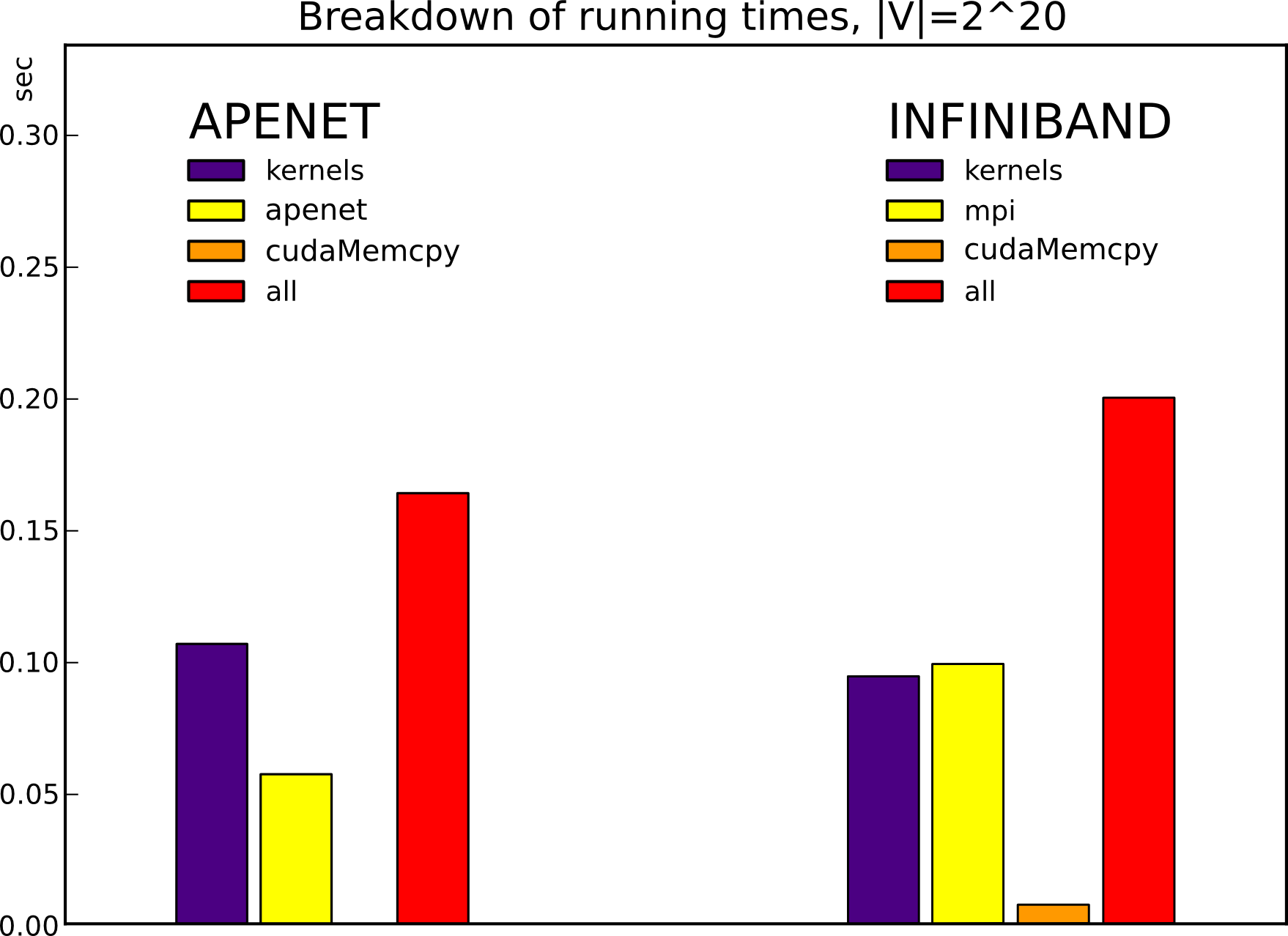
Although all CUDA kernels and the rest of the code are identical in the MPI-InfiniBand and the APEnet+ version of the code, we checked that the difference in performances is actually due to the communication part. In the four-nodes case, for this particular graph traversal, the communication time is 50% lower in the APEnet+ case (figure 12).
VI Conclusions
As it often happens, it is not easy to draw definitive conclusions on the effectiveness of GPU peer-to-peer, as it is strongly influenced by the maturity and efficiency of the particular APEnet+ implementation.
Anyway, we can state that the GPU peer-to-peer write protocol is quite effective; it has a small overhead and need minor modifications with respect to writing host memory.
On the other end, the peer-to-peer reading protocol is complicated for third-party devices, though minor technical modifications could improve it a lot; in some sense, it seems too close to the internal fine-grained memory architecture of the GPU. Moreover, the reading bandwidth limit around 1.5 GB/s (on Fermi) seems architectural, verified both at the PCIe transaction level and by the scaling with the pre-fetch window. On the other hand, the GPU peer-to-peer is by design more resilient to host platform idiosyncrasies, like PCIe bus topology and chip-sets bugs.
On Kepler, the BAR1 technique seems more promising. In many ways it supports the normal PCIe protocol for memory-mapped address spaces, both for reading and writing, so it requires minimal changes at the hardware level. The drawback is in platform support, as the PCIe split-transaction protocol among devices is known to be deadlock-prone, or at least sub-performing, on some PCIe architectures. Judging from our early experience, the BAR1 reading bandwidth could be positively affected by the proximity of the GPU and the third-party device, e.g. both being linked to a PLX PCIe switch.
As of the GPU peer-to-peer implementation on APEnet+, it seems to be effective especially in latency-sensitive situations. As synthetic benchmarks have shown, APEnet+ is able to outperform IB for small-to-medium message sizes when using GPU peer-to-peer. The advantage provided to the applications by this technique depends on several factors related to their communication pattern, i.e. message sizes, destination nodes, source and receive buffer types (host or GPU) etc., which in turn depend on simulation parameters like volume size, number of GPUs per node and number of cluster nodes. It depends also on the possibility of overlapping computation and communication. Anyway peer-to-peer on APEnet+ should provide a boost in strong scaling situations, where the communication pattern is usually dominated by small-size messages. Unfortunately, we are currently limited to an 8-nodes test environment; This is going to change in the next few months, when we will be able to scale up to 16/24 nodes.
Acknowledgments
The APEnet+ development is partially supported by the EU Framework Programme 7 project EURETILE under grant number 247846.
We thanks Timothy Murray, Joel Scherpelz and Piotr Jaroszynski for supporting our work, and Christopher Lamb for reviewing the paper.
References
- [1] M. Bernaschi, M. Bisson, M. Fatica, and E. Phillips. “An introduction to multi-gpu programming for physicists” The European Physical Journal - Eur. Phys. J. Special Topics 210, 17-31 (2012).
- [2] D. Rossetti, R. Ammendola, P. Vicini, A. Biagioni, O. Frezza, F. Lo Cicero, A. Lonardo, P.S. Paolucci, F. Simula, L. Tosoratto “APEnet+ project status” Proceedings of the XXIX International Symposium on Lattice Field Theory (Lattice 2011).
- [3] Orion Sky Lawlor “Message Passing for GPGPU Clusters: cudaMPI” IEEE Cluster PPAC Workshop 2009
- [4] CUDA-Aware OpenMPI distribution http://www.open-mpi.org/faq/?category=building#build-cuda
- [5] CUDA-Aware MVAPICH2 distribution http://mvapich.cse.ohio-state.edu/overview/mvapich2
- [6] M. Bernaschi, M. Bisson, D. Rossetti “Benchmarking of communication techniques for GPUs” Journal of Parallel and Distributed Computing, 73(2):250-255 (2013).
- [7] Ashwin Aji, James Dinan, Darius Buntinas, Pavan Balaji, Wu-chun Feng, Keith Bisset, and Rajeev Thakur. “MPI-ACC: An Integrated and Extensible Approach to Data Movement in Accelerator-Based Systems” Proc. 14th IEEE Intl. Conf. on High Performance Computing and Communications. (HPCC). Liverpool, UK. June 2012.
- [8] R. Ammendola, M. Guagnelli, G. Mazza, F. Palombi, R. Petronzio, D. Rossetti, A. Salamon, and P. Vicini. “APEnet: LQCD clusters à la APE” Nuclear Physics B - Proceedings Supplements, 140(0):826 – 828, 2005. Proceedings of the XXII International Symposium on Lattice Field Theory (Lattice 2004).
- [9] R. Ammendola, A. Biagioni, O. Frezza, F. Lo Cicero, A. Lonardo, P. Paolucci, R. Petronzio, D. Rossetti, A. Salamon, G. Salina, F. Simula, N. Tantalo, L. Tosoratto, and P. Vicini. “APEnet+: a 3D toroidal network enabling petaflops scale lattice QCD simulations on commodity clusters” Proceedings of The XXVIII International Symposium on Lattice Field Theory PoS(Lattice 2010)022 and arXiv:1012.0253v1.
- [10] D. Bureddy, H. Wang, A. Venkatesh, S. Potluri, D.K. Panda. “OMB-GPU: A Micro-Benchmark Suite for Evaluating MPI Libraries on GPU Clusters” Recent Advances in the Message Passing Interface, Lecture Notes in Computer Science, 7490:110-120, 2012.
- [11] M. Bernaschi, G. Parisi, L. Parisi “Benchmarking GPU and CPU codes for Heisenberg spin glass over-relaxation” Computer Physics Communications, 182(6):1265-1271 (2011).
- [12] A. G. Duane Merrill, Michael Garland. “High performance and scalable GPU graph traversal” Technical report, NVIDIA, 2011.
- [13] S. Hong, T. Oguntebi, and K. Olukotun. “Efficient parallel graph exploration on multi-core CPU and GPU” In International Conference on Parallel Architectures and Compilation Techniques (PACT), 2011 , pages 78 –88, oct. 2011.
- [14] Graph 500 benchmark www.graph500.org
- [15] E. Mastrostefano and M. Bernaschi. “Efficient breadth first search on multi-GPU systems” submitted to Journal of Parallel and Distributed Computing (August 2012).
- [16] D. Culler et al. “LogP: towards a realistic model of parallel computation.” Proceedings of the Fourth ACM SIGPLAN Symposium on Principles and Practice of Parallel Programming, Volume 28, Issue 7, p. 1-12, jul. 1993.
- [17] M Bernaschi, M Bisson, E Mastrostefano, D Rossetti. “Breadth first search on APEnet+.” Workshop on Irregular Applications: Architectures & Algorithms, Nov. 2012. To appear on SC 2012 Conference proceedings.