Theory of Absorption Induced Transparency
Abstract
Recent experiments (Angew. Chem. Int. Ed. 50, 2085 (2011)) have demonstrated that the optical transmission through an array of subwavelength holes in a metal film can be enhanced by the intentional presence of dyes in the system. As the transmission maxima occurs spectrally close to the absorption resonances of the dyes, this phenomenon was christened Absorption Induced Transparency. Here, a theoretical study on Absorption Induced Transparency is presented. The results show that the appearance of transmission maxima requires that the absorbent fills the holes and that it occurs also for single holes. Furthermore, it is shown that the transmission process is non-resonant, being composed by a sequential passage of the EM field through the hole. Finally, the physical origin of the phenomenon is demonstrated to be non-plasmonic, which implies that Absorption Induced Transparency should also occur at the infrared or Terahertz frequency regimes.
pacs:
78.67.-n,78.20.Bh,42.25.Bs,42.70.JkThe transmission of light through apertures has been attracting the attention of mankind for centuries. For instance, it was used in the invention of the camera obscura, it was at the root of the discussions on whether light has a corpuscular or wave nature, and nowadays it is central to the technique of optical lithography. A limiting factor for many applications is that the transmission process is severely impaired if the lateral hole dimension is smaller than the wavelength of light Bethe (1944). In the last fifteen years, several instances have been found in which light transmission through small holes is enhanced: (i) in arrays of sub-wavelength holes Ebbesen et al. (1998) and single holes surrounded by surface corrugations Lezec et al. (2002), where light scattered by each hole, instead of being reflected, couples to surfaces modes which allows the build-up of constructive interferences Martín-Moreno et al. (2001); Liu and Lalanne (2008), (ii) through localized resonances in single sub-wavelength holes Koerkamp et al. (2004); Degiron et al. (2004), occurring close to the cutoff frequency of the hole, which can be seen either as a zero-order Fabry-Perot resonance García-Vidal et al. (2005) or transmission in an Epsilon-Near-Zero material Silveirinha and Engheta (2006), and (iii) for Brewster-angle transmission Alù et al. (2011), appearing at oblique illumination when the holey surface is impedance matched to the medium of incidence. All these phenomena are now generically known as Extraordinary Optical Transmission (EOT) Garcia-Vidal et al. (2010). Recently, another case of EOT has been unveiled: Absorption Induced Transparency (AIT) Hutchison et al. (2011). Roughly speaking, AIT refers to an enhancement in the transmittance through hole arrays that appears when an absorbing dye is deposited on them. The most intriguing characteristic of AIT is that the transmission peak, in the combined hole array plus dye system, appears at the spectral position where the bare dye presents resonant absorption. Several mechanisms have been proposed, such as dipole-induced dipole interaction between molecules and localized SPPs, cutoff function modification, changes in Fresnel’s coefficients Hutchison et al. (2011), and coherent interactions between the hybridized fields of the oscillating elements present in the system Weis et al. (2011), but the origin of AIT still remains unclear.
In this work we elucidate the physical origin of AIT, which we ascribe mainly to the change in the propagation constant inside the holes when filled by the dye. This is originated by the highly dispersive optical response of the dye at frequencies close to the absorption band. In particular, AIT transmission maxima very closely coincide with minima in the imaginary part of the propagation constant of the hole, and vice versa. We predict that also single holes should exhibit AIT. We also show that the effect does not have a plasmonic origin and it is thus not restricted to metal films in the optical regime.
Through this paper the electromagnetic fields (and from them the reflectance, transmittance and absorbance spectra) are computed using the Finite Difference Time Domain method Taflove and Hagness (2005), and more particularly, the implementation to study silver films described in Rodrigo et al. (2008).
Let us first analyze the experimental results on AIT, reported for square arrays of circular holes carved on a silver film, placed on a glass substrate, and illuminated at normal incidence Hutchison et al. (2011). The film thickness is nm, and the period nm (see schematics in Fig. 1(b)). These parameters will be kept fixed throughout this work. The optical response of the dye (which hereafter will be denoted as the absorber) used in the experiments is described by a frequency-dependent dielectric constant . This classical electrodynamics approach is fully justified by the high molecular concentration levels and low laser powers used in experiments Fischer et al. (2002); Valmorra et al. (2011).
In order to implement a realistic model with a minimum of material parameters, we consider that is characterized by a single Lorentzian term: . The different parameters are fitted to reproduce the main absorption peak appearing when an unperforated film is coated with a nm thin absorber (see Fig. 1 in Ref. Hutchison et al. (2011)). We obtain (host medium), , eV (line width), and eV (transition frequency).
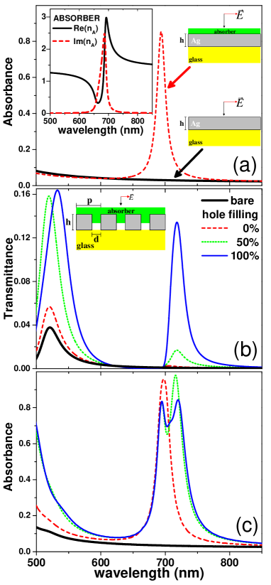
Figure 1(a) shows the absorption spectrum for the considered silver film, with and without the 30 nm thick absorbing layer (dashed curve and solid curve, respectively). As expected, light is mainly reflected by the bare flat silver film, with an absorbance spectrum showing a smoothly decreasing trend as the wavelength increases. The presence of the thin absorber layer induces a large absorption peak, which is correlated with the resonant behavior in the imaginary part of the absorber refractive index, , represented in the inset of Fig 1(a).
Figure 1(b) renders the transmittance spectra for a hole array (with nm diameter circular holes) on a glass substrate, for different configurations of the absorber. The thick solid line renders the transmittance for the case when no absorber is present, showing an EOT peak at nm. At this wavelength the waveguide modes inside the hole are evanescent (the cutoff wavelength for the fundamental mode is nm), and the EOT peak originates from the grating-assisted resonant excitation of surface electromagnetic modes at the glass-metal interface Ebbesen et al. (1998); Martín-Moreno et al. (2001) (surface plasmon polaritons, SPPs, in the optical regime). The other configurations analyzed in Fig. 1(b) have a nm absorber thin overlayer and different degrees of hole filling: no absorber inside the hole (dashed line), absorber filling 50% of the hole length (dotted line) and holes completely filled (thin solid line). The addition of the absorber induces two apparent changes to the transmittance spectra. First, the EOT peak at nm is slightly increased by the presence of the over layer (due to the stronger binding of the SPP to the surface and the corresponding enhancement of the SPP-hole coupling), and more strongly boosted by the filling of the holes. In this case, the mechanism behind is the hybridization between SPPs and localized resonances Koerkamp et al. (2004); Degiron and Ebbesen (2005), which occurs near the cut-off wavelength García-Vidal et al. (2005); Carretero-Palacios et al. (2012). As in the wavelength range from nm to nm, the localized resonance is expected near nm, thus overlapping with the SPP. The second change is, in agreement with the experimental finding Hutchison et al. (2011), the appearance of the AIT peak at nm. Our calculations show that the intensity of the AIT peak strongly depends on the degree of filling of the holes: it is negligible when the absorber does not enter into the hole and maximum when the hole is completely filled. This transmittance peak is spectrally located close to the absorption line of the dye, but it is redshifted by nm (in fact, a closer inspection reveals that the transmittance has a minimum very close to the maximum of ). This shift is even more apparent in the absorbance, which is shown in Fig. 1(c) for the same systems considered in Fig. 1(b). This magnitude, presents a double-peak structure in the AIT region. One absorption maximum occurs at the same spectral position as that of the absorbing overlayer and, as the transmittance in the hole array is small there, it does not depend much on whether the holes are filled. The other absorption maximum coincides with the transmission peak thus, it only occurs when the holes are at least partially filled.
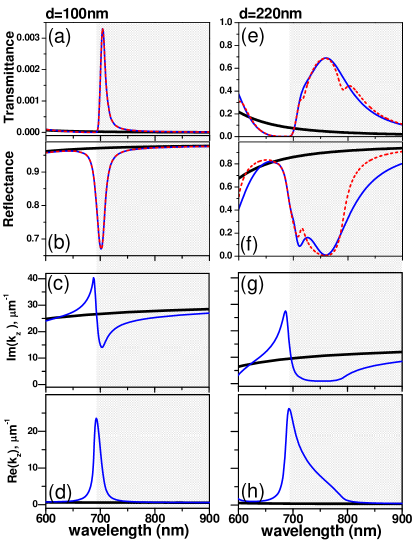
AIT-peaks can be related to the spectral features of the propagation constant of filled holes, , which has a implicit analytical expression for circular waveguides Jackson (1975). This is illustrated in Fig. 2, where we focus on the AIT spectral region. We simultaneously represent the transmittance and reflectance for two hole arrays (characterized by different hole diameters) together with the imaginary and real part of inside the holes. In order to show that the presence of the substrate is not essential, the arrays are considered free standing (dielectric constant of substrate equal to unity). Both period nm and film thickness nm are as in the previous figures. In each panel, the thick continuous curves are for empty holes while thin ones are for holes filled with the absorber (dashed lines will be discussed later on). The correlation between propagation constant and scattering coefficients shows that the enhancement of the transmission is due to a reduction in the imaginary part of , and it indicates that AIT has a localized character. Notice also that transmittance peaks are narrower than reflection dips. This occurs because reflectance decreases when transmittance increases, but also when absorption increases, which occurs when the imaginary part of is enhanced (anomalous dispersion region).
A surprising result of the calculations is that AIT is not a resonant effect, at least in the range of geometrical parameters considered in the original experiments. This can be demonstrated by expressing the zero-order transmission () and reflection () amplitude coefficients through the whole structure in terms of the partial reflection coefficient at a single interface (). For a symmetric environment, the summation of multiple scattering processes gives and . These expressions have been used in the past to analyze EOT phenomena Martín-Moreno et al. (2001); de Abajo (2007); Garcia-Vidal et al. (2010). Resonant transmission is typically observed when the denominator in takes values close to zero. Of course, the previous expressions also apply to AIT but, in this case the multiple scattering terms can be neglected. This is readily done by considering that the reflection process only involves the first interface, so that , while the transmission through the array is a three-step process: transmission into the hole, propagation inside it and transmission out of the hole, leading to . The dashed red lines in the transmittance and reflectance panels in Fig. 2 are obtained using this approximation, with the coefficient computed numerically with the FDTD method. The excellent agreement with the full result confirms that AIT is not a resonant phenomenon in the sense of requiring the resonant built-up provided by multiple scattering. Instead, AIT transmission can be seen as a sequential process, favored by the reduced evanescence inside the holes induced by the absorber. This occurs at the long-wavelength side of the absorption resonance, where Kramers-Kronig relations provide a combination of large and yet relatively small .
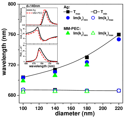
It is possible, following previous work on EOT Martín-Moreno and García-Vidal (2008); Garcia-Vidal et al. (2010) and spoof plasmons Pendry et al. (2004), to develop an analytical minimal model for AIT. For that, the electromagnetic fields in different regions of space are expanded in the corresponding eigenfunctions, with expansion coefficients that are fixed by imposing the appropriate boundary conditions. Two approximations are then enforced: (i) only the least decaying mode inside the hole and the zero-order diffraction order in the radiation regions are considered, and (ii) the properties of the metal only enter in that the hole radius is phenomenologically enlarged by the actual skin depth Martín-Moreno and García-Vidal (2004); otherwise the metal is represented as a perfect electrical conductor (PEC, ). Within this simple model (which will be denoted MM-PEC) it is straightforward to show that the perforated metal film with filled holes behaves as a uniform film characterized by a dielectric constant , and an effective magnetic susceptibility . In this expressions , is the cut-off wavelength of an unfilled circular waveguide in PEC, , nm for silver in the optical regime Rodrigo et al. (2008), and . The inset to Fig. 3 shows, for an array of holes with diameter nm, the comparison between the exact result and that obtained with the minimal model for transmittance, and also the real and imaginary part of the propagation constant inside the film. The good agreement found for all these quantities validate the minimal model. This agreement is not restricted to the particular diameter considered. In Fig. 3 we represent the spectral position for both minimum and maximum AIT transmittance, together with the corresponding values for , computed both exactly and within the MM-PEC model. These results confirm the correlation between transmittance and discussed above. It also stresses that, as AIT does not have a plasmonic origin, it should also appear at shorter frequency regimes (THz, mm…) where the PEC approximation for the metal is even more accurate (of course, in this case, the holes should be filled by an absorber with an absorption line in the required frequency range).
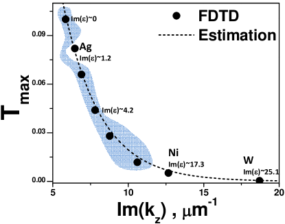
It could be argued that the experimentally demonstrated existence of AIT for hole arrays when the film is made of Ag but not when it is made of either Ni or W Hutchison et al. (2011), points to a plasmonic origen. This is not the case, as AIT is governed by the propagation constant inside the hole. This is illustrated in Fig. 4, that shows the maximum transmittance of the AIT peaks through fully filled hole arrays in different metals: Ni, W, and a series of hypothetical metals, where the real part of the dielectric constant is essentially that of Ag (so that the skin depth is practically the same in all the series), but the imaginary part is modified. The transmittance is represented as a function of for the least evanescent mode inside the waveguide (evaluated at the spectral position of maximum transmittance). The good agreement with the estimation (which depends only on the EM properties inside the hole) shows that AIT in “bad” metals is hampered by the enhanced absorption inside the hole, and not by the existence, or lack of it, of surface electromagnetic modes at the metal surface.
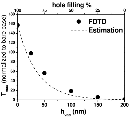
Thus, the main physical mechanism involved in AIT, at least in the range of parameters experimentally considered, is the reduction in the opacity of the metal film due to the filling of the holes with a material with large dielectric constant and moderate absorption (so that multiple scattering inside the hole is not relevant). The asymmetric shapes of the transmission peaks are, therefore, due to the spectral asymmetry of the real part of the refractive index close to a resonance, and not to any “Fano-like” resonant effect. This conclusion is further supported by analyzing the maximum transmission for arrays of partially-filled holes (where the hole is filled a distance from the top surface and unfilled otherwise). Figure 5 shows, together with the FDTD results, the curve . This expression is obtained by assuming that the transmission through the structure is a sequential process, in which the propagation in each region is dominated by the corresponding propagation constant ( in the un-filled hole region and in the filled one). Again, the good agreement between the full calculations and this extremely simplified model indicates that the main factor governing AIT is the modification of the propagation constant.
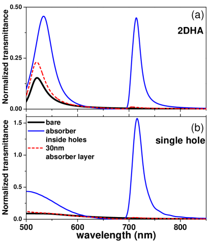
It is also interesting to study whether AIT also occurs for isolated holes. In Fig. 6(a) we compare the transmittance through both a hole array (top panel) and a single hole (bottom panel). The period, metal thickness, hole diameter and substrate are as in the case considered in Fig. 1. We analyzed three different configurations: no absorber, a nm absorber overlayer with empty holes, and fully filled holes without overlayer. These calculations confirm the hybrid nature of the EOT peak appearing at nm, which for hole arrays already occurs when no dye is present, while in a single hole only occurs when the dye fills the hole and induces the presence of localized resonances. Regarding AIT, the fact that, for both single holes and hole arrays, the peak emerges only when holes are filled confirms that AIT is a localized effect, where collective interactions between holes are not essential.
To conclude, we have demonstrated that AIT requires the presence of absorbers,
like molecules embedded in a polymer, inside
the holes of a perforated metal film. Our calculations predict that AIT should also occur in single holes,
having thus a localized character.
We have found that their spectral position and width, and their intensity, are
mainly controlled by the imaginary part of the
propagation constant of holes.
We have demonstrated that hole arrays in the AIT regime behave like a
metamaterial, characterized by a dielectric constant composed by a Drude plasma term
(of geometric origin) plus a Lorentz term arising by the presence of the absorber.
We have shown that AIT peaks are non-plasmonic in character, so they are predicted to occur
in frequencies regimes other than the optical.
This opens the door for detection spectroscopy of chemical compounds
characterized by sharp absorption lines in the THz or microwave regimes.
Acknowledgements.
We acknowledge support from the Spanish Ministry of Science and Innovation under projects MAT2011-28581-C02, and CSD2007-046-Nanolight.es.References
- Bethe (1944) H. A. Bethe, Phys. Rev. 66, 163 (1944).
- Ebbesen et al. (1998) T. W. Ebbesen, H. L. Lezec, H. F. Ghaemi, T. Thio, and P. A. Wolff, Nature 391, 667 (1998).
- Lezec et al. (2002) H. J. Lezec, A. Degiron, E. Devaux, R. A. Linke, L. Martín-Moreno, F. J. García-Vidal, and T. W. Ebbesen, Science 297, 820 (2002).
- Martín-Moreno et al. (2001) L. Martín-Moreno, F. J. García-Vidal, H. J. Lezec, K. M. Pellerin, T. Thio, J. B. Pendry, and T. W. Ebbesen, Phys. Rev. Lett. 86, 1114 (2001).
- Liu and Lalanne (2008) H. Liu and P. Lalanne, Nature 452, 728 (2008).
- Koerkamp et al. (2004) K. J. K. Koerkamp, S. Enoch, F. B. Segerink, N. F. van Hulst, and L. Kuipers, Phys. Rev. Lett. 92, 183901 (2004).
- Degiron et al. (2004) A. Degiron, H. J. Lezec, N. Yamamoto, and T. W. Ebbesen, Optics Communications 239, 61 (2004).
- García-Vidal et al. (2005) F. J. García-Vidal, E. Moreno, J. A. Porto, and L. Martín-Moreno, Phys. Rev. Lett. 95, 103901 (2005).
- Silveirinha and Engheta (2006) M. Silveirinha and N. Engheta, Phys. Rev. Lett. 97, 157403 (2006).
- Alù et al. (2011) A. Alù, G. D’Aguanno, N. Mattiucci, and M. J. Bloemer, Phys. Rev. Lett. 106, 123902 (2011).
- Garcia-Vidal et al. (2010) F. J. Garcia-Vidal, L. Martin-Moreno, T. W. Ebbesen, and L. Kuipers, Rev. Mod. Phys. 82, 729 (2010).
- Hutchison et al. (2011) J. A. Hutchison, D. M. O’Carroll, T. Schwartz, C. Genet, and T. W. Ebbesen, Angewandte Chemie International Edition 50, 2085 (2011).
- Weis et al. (2011) P. Weis, J. L. Garcia-Pomar, R. Beigang, and M. Rahm, Opt. Express 19, 23573 (2011).
- Taflove and Hagness (2005) A. Taflove and S. C. Hagness, Computational Electrodynamics: The Finite-Difference Time-Domain Method (Third edition) (Artech House, Boston, 2005).
- Rodrigo et al. (2008) S. G. Rodrigo, F. J. García-Vidal, and L. Martín-Moreno, Phys. Rev. B 77, 075401 (2008).
- Fischer et al. (2002) U. C. Fischer, E. Bortchagovsky, J. Heimel, and R. T. Hanke, Appl. Phys. Lett. 80, 3715 (2002).
- Valmorra et al. (2011) F. Valmorra, M. Bröll, S. Schwaiger, N. Welzel, D. Heitmann, and S. Mendach, Appl. Phys. Lett. 99, 051110 (2011).
- Degiron and Ebbesen (2005) A. Degiron and T. W. Ebbesen, J. Opt. A: Pure Appl. Opt. 7, S90 (2005).
- Carretero-Palacios et al. (2012) S. Carretero-Palacios, F. J. García-Vidal, L. Martín-Moreno, and S. G. Rodrigo, Phys. Rev. B 85, 035417 (2012).
- Jackson (1975) J. D. Jackson, Classical Electrodynamics 2nd edition (Wiley, New York, 1975).
- de Abajo (2007) F. J. G. de Abajo, Reviews of Modern Physics 79, 1267 (2007).
- Martín-Moreno and García-Vidal (2008) L. Martín-Moreno and F. J. García-Vidal, J. Phys.: Condens. Matter 20, 304214 (2008).
- Pendry et al. (2004) J. B. Pendry, L. Martín-Moreno, and F. J. García-Vidal, Science 305, (5685): 847 (2004).
- Martín-Moreno and García-Vidal (2004) L. Martín-Moreno and F. J. García-Vidal, Opt. Express 12, 3619 (2004).