The ASTRI Mini-Array Software System
Abstract
ASTRI (“Astrofisica con Specchi a Tecnologia Replicante Italiana”) is a Flagship Project financed by the Italian Ministry of Education, University and Research, and led by INAF, the Italian National Institute of Astrophysics. Main goals of the ASTRI project are the realization of an end-to-end prototype of a Small Size Telescope (SST) for the Cherenkov Telescope Array (CTA) in a dual-mirror configuration (SST-2M) and, subsequently, of a mini-array composed of a few SST-2M telescopes to be placed at the final CTA Southern Site. Here we present the main features of the Mini-Array Software System (MASS) that has a central role in the success of the ASTRI Project and will also serve as a prototype for the CTA software system. The MASS will provide a set of tools to prepare an observing proposal, to perform the observations specified therein (monitoring and controlling all the hardware components of each telescope), to analyze the acquired data online and to store/retrieve all the data products to/from the archive.
1 Introduction
ASTRI is a flagship program financed by the Italian Ministry of Education, University and Research (MIUR) to develop special technologies suitable for the ambitious CTA Observatory [1]. The CTA is composed by many tens of telescopes divided in three kinds of classes, in order to cover the energy range from a tens of GeV (Large Size Telescope, LST), to a tens of TeV (Medium Size Telescope, MST), and up to 100 TeV and beyond (Small Size Telescope, SST) [8]. Within this framework, INAF, the Italian National Institute of Astrophysics, is currently [9]: developing an end-to-end prototype of SST in a dual-mirror configuration (SST-2M) to be tested under field conditions, and scheduled to start data acquisition in late 2014; the design and deployment of a mini-array of SST-2M as a first seed for the CTA Observatory.
In the framework of the ASTRI Project, the Mini-Array Software System (MASS) has the task of making it possible to operate both the ASTRI SST-2M and the Mini-Array under the constraints and requirements contained in the ASTRI Operation Modes and User
Requirements document.
The MASS is being designed to allow a member of the ASTRI Collaboration (the user)
to perform all the steps needed to prepare and execute a scientific observing run.
The MASS will provide a set of tools to the user to prepare an observing proposal,
to perform the observations specified therein, to analyze the acquired data online and to retrieve
all the data products from the archive.
Also, the MASS will provide the software
for the management and administration of proposals, scheduling of the observations, instrument operations and use of the archive.
Furthermore the design of the MASS must be compliant with the CTA
Data Management (CTA-DM) and CTA Data Acquisition and Array Control (CTA-ACTL)
requirements and guidelines.
The base unit of the ASTRI Mini-Array is the ASTRI SST-2M and in this paper we will describe the main characteristics of the software dedicated to control it.
2 THE ASTRI SST-2M Hardware Architecture of the Control System
The ASTRI SST-2M is a complex system including several subsystems, such as telescope, camera and safety systems, that have to be monitored in order to get, in real time, the current status and the availability of each component. Also, the different parts of the system have to be controlled in order to perform the operations requested by the users (astronomers, operators, engineers, etc.). A detailed description of the mechanical, kinematical and optical characteristics of the SST-2M can be found here [4].
The ASTRI SST-2Mtelescope Azimuth and Elevation servo systems are based on brushless motors. Absolute encoders monitor the position of the axes. State of the art PC-based technology is used to control the pointing and tracking of the telescope; this eliminates the need for complex and expensive special hardware (such as a Programmable Logic Controller), since the functionality (control, regulation, motion control and visualization) of this hardware can be handled by the software. A fieldbus is used to connect the secondary servo systems, the Active Primary Mirror (M1) and the Secondary Mirror (M2) piston/tilt control system as well as other I/O devices. A large number
of temperature sensors, strain-gauges and accelerometers are distributed along
the telescope structures, mirrors and mirror supports. Given the pointing requirements,
arcsec rms, up to of zenith angle, two monitoring systems are installed:
-
•
One wide field CCD camera (field of view of ) mounted on the M1 support to obtain an astrometric solution for the parallactic angle and also useful to derive and monitor the pointing model of the telescope (sampling rate of the sky images about 1 Hz);
-
•
One Giga Ethernet CCD camera mounted on the ASTRI camera and 18 laser diodes (one for each M1 dish panel) using direct telescope optics to monitor panel and secondary flexures due to wind and gravity (sampling rate for images about 10 Hz).
The ASTRI Camera Back-End is in charge of delivering the Camera bulk data to the Camera Server through a TCP/IP connection on a 1 (possibly 10) Gbit fiber Ethernet LAN. The system includes several other auxiliary devices such as the time distribution system, which will be based on a GPS receiver and NTP server (with possible use of the CERN White Rabbit technology for the mini-array, but not the first telescope prototype). Furthermore, there are other devices dedicated to the site and environmental monitoring.
3 ASTRI SST-2M and Mini-Array System Software design Concept
The collection of sub-systems described in section 2, must act in concert under
the control of the MASS to achieve the goals stated in the ASTRI System Requirement
Document (SRD) both for the single telescope and for the Mini-Array. In particular
the general operations that should be managed by the MASS software are given in
the ASTRI Operation Procedures document and User Requirements document and are compliant with the CTA requirements.
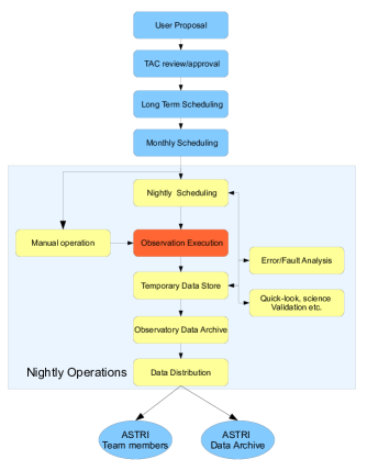
The information flow that will be managed by the MASS is shown in Figure 1.
-
•
The ASTRI Team user initiates the Observing cycle by preparing and submitting a proposal to the ASTRI Time Allocation Commitee (TAC). After the proposal has been reviewed and accepted it is inserted in the ASTRI Data Archive. The user observation is then included in the Observation plan and in the long term Operations Plan.
-
•
The scheduling system will include the observation in the appropriate nightly schedule and it will be performed by the MASS Observation Execution subsystem. The raw data collected during the observation will then be stored in a temporary archive and sent to the quick-look processing pipeline for system and data quality validation.
-
•
After data quality validation, data will be stored in the on-site Observatory Database ready for post-processing and the delayed delivery to the off-site ASTRI Data Archive in Rome. The user will receive notice of the availability of the data and will be able to retrieve these data through a Web-based service and will be able to analyze the data using the ASTRI Science Analysis tools.
-
•
A central role in the design of the MASS is assigned to the Observation Execution (MASS-OE) subsystem, which is responsible for the actual observations requested by the user and approved by the ASTRI TAC. This subsystem controls and monitors all ASTRI hardware present at the site: telescopes, cameras, auxiliary devices, safety devices, etc. It can work automatically but an operator will normally supervise it.
3.1 The MASS Observation Execution Subsystem
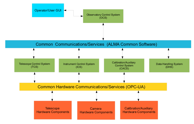
MASS-OE is a distributed system that, as in many of the most recent telescope control system designs, is composed of the following main components (see Figure 2):
-
•
The observatory control system (OCS).
-
•
The telescope control system (TCS).
-
•
The instrument control system (ICS).
-
•
The data handling system (DHS).
-
•
The calibration/auxiliary control system (CACS)
3.1.1 The observatory control system
The OCS is responsible for high-level ASTRI operations; it provides user interfaces, scheduling and execution of observations, system monitoring, and coordination of the TCS and ICS actions to acquire and monitor bulk data, which then will be stored and displayed by the DHS. The OCS also provides high-level graphical user interfaces (GUIs) for system operators and observers, together with system and environment status monitors.
3.1.2 The telescope control system
The scope of the TCS is to provide a high quality stable image of a specified point on the sky to the ASTRI Camera at the focal plane. The main tasks of the TCS are coordinating, monitoring and controlling the activities of its subsystems under instruction from the OCS. The TCS does not include direct control of any ASTRI hardware, this is the responsibility of its subsystems, e.g., the Mount Control System and the Active Mirror Control System which will communicate with the dedicated OPC (Open Productivity & Connectivity) -UA (Unified Architecture)111http://www.opcfoundation.org/ servers installed on the Telescope Control Unit (TCU) and Active Mirror Control Unit (AMCU), the two rack-mounted industrial computers on board the telescope. The software installed on these two computers is dedicated to the following tasks:
-
•
command telescope slewing and tracking.
-
•
monitor and control the thermal loads on the telescope;
-
•
monitor and control the active optics systems;
-
•
monitor and control the pointing monitor camera;
-
•
monitor and control other simple on/off devices
The TCS is not responsible for time-critical operations. All real-time functions are performed at the level of the TCU and the AMCU; this includes all the astronomical coordinate transformations and pointing model corrections needed to produce the commanded position of the telescope at a given time in mount coordinates (i.e., encoder coordinates). In our approach the telescope is a stand-alone system able to manage all the primary functions needed to acquire a celestial source starting from a minimal set of input parameters (e.g., coordinates of the target). In this way high level software should be concerned only with the business logic and not with the details of the hardware operation.
3.1.3 The instrument control system
The ICS provides all software components used to configure, control and acquire monitoring data from the ASTRI Camera [5]. The ICS provides the capabilities for the monitoring and control of the ASTRI Camera and will allow direct access to all devices controlled by the Detector Control system (DCS) and the Camera Auxiliary Devices Control (CADC).
3.1.4 The data handling system
The DHS system is responsible for the on-site storing and processing of all the data produced
by the system (ASTRI Camera bulk data, calibrations, engineering data, housekeeping, etc.). Also, the DHS is responsible for the delivery of the relevant data to the ASTRI off-site archive. A more detailed description of the ASTRI archive design is given here [2]
The ASTRI Camera bulk data are acquired and monitored by the ASTRI Data Acquisition
system (DAQ). According to the CTA design principle, the data acquisition of the ASTRI Camera is assigned to one
dedicated computer, the ASTRI Camera Server, in which the Detector DAQ Software (DDS) is deployed and runs. The DAQ is
in charge of collecting the data from the Camera Back End Electronics. A prototype of the DDS software is under development.
The data acquired by the DAQ will be processed by the on-site Analysis pipeline which will run the ASTRI Science Analysis Tools developed
taking into account all the peculiarities of the analysis of Cherenkov data. Indeed,
the Cherenkov data are more complicated to analyze than data produced by instruments that take
direct images of the sky. An extensive processing chain is needed to derive the
scientific characteristics of the primary gamma ray from the Cherenkov images of the
air showers detected by the cameras. The data analysis chain will also
depend critically on a wide range of parameters related to both the instrument configuration
and the observing conditions. In preparation for this analysis, a complex set of simulations must also
be generated to calibrate data in order to estimate both the “hadroness” of the incoming
primary particle and its energy. The Monte Carlo simulation activities ongoing in ASTRI are reported here [3] [montecarlo1].
3.1.5 The calibration/auxiliary control system
The CACS includes several components dedicated to monitor the site condition and provide essential services. Most of these devices will be installed and tested at the Serra La Nave site (see [6]), where the ASTRI SST-2M prototype telescope will be installed, the following auxiliary instrumentation is part of the CACS and is described in [6] :
-
•
The weather station and the rain sensor
-
•
The Time Synchronization and distribution system (GPS, etc)
-
•
The All-Sky Fish-Eye camera
-
•
The Sky Quality Monitor (SQM)
-
•
The UVscope-UVSiPM complex
4 The MASS Interprocess Communication frameworks
From a communications and integration perspective, the MASS-OE is a distributed system of semi-autonomous objects interacting with each other through a software communications (middleware) backbone.
4.1 The ALMA Common Software framework
The MASS software will use the ALMA Common Software (ACS) framework222http://www.eso.org/ãlmamgr/AlmaAcs/index.html, developed as the foundation for the software system for the Atacama Large Millimeter/submillimeter Array (ALMA, see e.g. [11]). Furthermore, several aspects of CTA (and Mini-Array) system operations are nearly the same as those of ALMA. For instance:
-
•
the control and synchronization of arrays of telescopes/antennas;
-
•
the dynamic scheduling of observations;
-
•
the acquisition of high-rate data and its storage in petabyte-scale archives;
-
•
the monitoring, storage and analysis of data from hundreds to thousands of sensors mounted on telescopes and instruments;
-
•
the use of scripts to implement diverse observing modes.
ACS, developed by the European Southern Observatory (ESO) for the ALMA project, provides the communication and coordination facilities for the main software components. Also it provides mechanisms for monitoring, logging and alarm management. It facilitates distributed development as well as distributed operations through a component-container paradigm. Individual developers concentrate on the creation and testing of components that, following a standard interface definition and protocol, are straightforward to integrate and test with other components in the system.
Applications are built with ACS as many independent components that communicate with each other using a number of common services. Typical technical aspects of system integration, such as distribution, deployment and location of other components, are hidden from the developers. All these technical issues are the responsibility of containers provided by the framework.
4.2 The OPC-UA framework
With respect to the ALMA control software a simplification introduced in the MASS-OE is represented by the use of the standard OPC-UA to access all telescopes devices. This will allow us to decouple high-level control software from the specific hardware device used and from proprietary communication protocols.
OPC-UA is designed to be independent of the operating system. It can be deployed on Linux, Windows XP Embedded, VxWorks, Macintosh OS X, Windows 7, and classical Windows platforms. This also enables OPC to communicate over networks through Web Services. Client software is already available that enables access to OPC-UA servers by ACS components.
We have performed some tests using the Java OPC-UA console server and client from ProSys and a Java OPC-UA graphical client from UaExpert. Also we have tested the integration between ACS and OPC-UA. The results of these tests were encouraging and OPC-UA will be used as the standard communication protocol to access all ASTRI SST-2M and Mini-Array devices.
5 Conclusions
Here we presented the MASS software that will make possible to operate the ASTRI mini-array to perform the first scientific observations of a variety of sources (see [10]) from the southern CTA site. The MASS will be tested on the ASTRI SST-2M prototype that will be installed at the Serra La Nave site in 2014.
Acknowledgment: This work was partially supported by the ASTRI Flagship Project financed by the Italian Ministry of Education, University, and Research (MIUR) and led by the Italian National Institute of Astrophysics (INAF). We also acknowledge partial support by the MIUR Bando PRIN 2009.
References
- [1] M. Actis, et al., Exp. Astr. 32, 193 (2011), 1008.3703.
- [2] L.A. Antonelli et al., id_0925, these proceedings
- [3] C. Bigongiari et al., id_0564, these proceedings
- [4] R. Canestrari et al., id_468, these proceedings
- [5] O. Catalano et al., id_0111, these proceedings
- [6] M. C. Maccarone et al., id_0110, these proceedings
- [7] F. Di Pierro et al., id_0563, these proceedings
- [8] G. Pareschi et al., id_0466, these proceedings
- [9] G. Pareschi et al., [The ASTRI Collaboration], (in preparation)
- [10] S. Vercellone et al., id_0109, these proceedings
- [11] A. Wootten; A. R. Thompson, A. Richard, 2009, Proceedings of the IEEE, Vol. 97, Issue 8, p.1463-1471