A large-area single photon sensor employing wavelength-shifting and light-guiding technology
Abstract
Large-scale underground water-Cherenkov neutrino observatories rely on single photon sensors whose sensitive area for Cherenkov photons one wants to maximise. Low dark noise rates and dense module spacing will thereby allow to substantially decrease the energy threshold in future projects. We describe a feasibility study of a novel type of single photon sensor that employs organic wavelength-shifting material (WLS) to capture Cherenkov photons and guide them to a PMT readout. Different WLS materials have been tested in lab measurements as candidates for use in such a sensor and photon capture efficiencies as high as 50 % have been achieved. Based on these findings we estimate that the effective photosensitive area of a prototype built with existing technology can easily exceed that of modules currently used e. g. in IceCube. Additionally, the dark noise rate of such a module can be exceptionally low in the order of 10 Hz. This is of special importance when targeting low-energy neutrinos that yield only few photons that need to be distinguished from noise hits.
1 Motivation
Current large-scale water Cherenkov detectors in neutrino physics—such as IceCube [1] or SuperKamiokande [2]—instrument large amounts of water or ice with photosensitive devices. Efficient collection of the Cherenkov light is usually achieved by using large numbers of large photomultiplier tubes (PMTs). The fluxes and energies accessible by the experiment are then determined by the total mass of instrumented material, the density of instrumentation and the photo-collection area of each sensor. For IceCube, more than 5000 10” PMTs have been deployed into one km3 of ice, which detect a sufficient number of photons for neutrinos exceeding an energy of 100 GeV.
When one intends to lower the energy threshold significantly while keeping the effective mass at the megaton-level to target e. g. MeV neutrinos from extragalactic supernovae, two problems arise. Firstly, the noise rate of PMTs is proportional to their cathode area, so at some point a low-energy event that only has a low photon multiplicity can easily be mimicked by a random coincidence of module noise hits [3]. Secondly, covering an effective photosensitive area exceeding that of current experiments by factors of tens with conventional PMT technology is a significant (financial) challenge.
In the following we will describe the Wavelength-shifting Optical Module (WOM), a single photon sensor that can be used in extreme environments such as the deep antarctic glacial ice and has a total sensitive area exceeding that of current technology sensors by a factor of a few while its noise rate is reduced by up to two orders of magnitude. While the potential of the technology is manyfold, we concentrate our efforts on the future extensions of IceCube.
2 The wavelength-shifting optical module
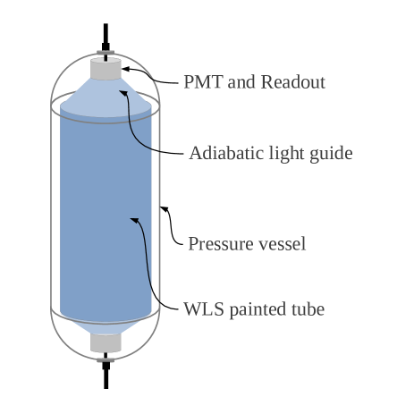
The main idea of the WOM is to increase the sensitive area of a PMT by using passive components that act as light collectors and concentrators (a sketch of the module design is shown in Fig. 1). Due to Liouville’s theorem, mirrors or lenses can not be used for this purpose, however, by introducing a wavelength shift (at the cost of a short time delay), this limitation can be overcome.
We envision cylindrical tubes that have wavelength-shifting properties. These tubes collect Cherenkov photons on their outer surface. These Cherenkov photons, which are mainly in the UV regime, are absorbed and then re-emitted isotropically at a larger wavelength within the tube. The isotropic emission ensures that a large fraction of the photons, which were incident roughly perpendicular to the surface, will now be captured inside the tube and then guided towards the end via multiple total internal reflection.
At both ends of the tube, small high-efficiency PMTs will be placed that read out the incoming photons. Since their spectrum has been shifted away from UV towards the optical blue, it is now better suited for readout by conventional PMTs as those are usually most sensitive in the optical blue and green.
The whole assembly will be enclosed by a transparent pressure vessel that protects the components from physical damage. It will also ensure that the wavelength-shifting tube is surrounded by a small gap of air and not in direct optical contact with the outside (e. g. the glacial ice). Although an optical contact to the surroundings usually is desirable to gather as many photons as possible, in our case a large difference in refractive index is needed to achieve efficient total internal reflection.
The three most important components of the WOM, for which we will discuss details of their properties, are:
-
•
the pressure housing
-
•
the PMT
-
•
and the wavelength-shifting tube.
For the pressure housing, apart from mechanical stability111Static pressure of up to 10000 psi can occur during the freeze-in process when deploying in deep antarctic ice., two requirements have to be met. Firstly, optical transparency has to be guaranteed not only in the optical but also in the UV regime down to 250 nm. Secondly, the material needs to have a high radio purity. In regular glass, 40K is a common contamination and its decay would give rise to a very high module noise rate. It turns out that fused quartz glass is a very good choice, having a transparency of 90 % at 250 nm and an activity of only 0.02 Bq/kg [4].
As a possible PMT we consider a prototype that has an novel photocathode with enhanced green sensitivity [5]. Although for this prototype no noise measurements at low temperature are available, for similar models typical noise rates are reported to be below 1 Hz per cm2 of cathode area at a temperature of –30 ∘C [6].
The wavelength-shifting tube can be made of quartz glass as well although the wall thickness can be much thinner, since there is no pressure inside. This inner cylinder will be covered by a thin film of wavelength-shifting material. First tests have been done with samples produced by dip-coating 20 mm and 5 mm diameter glass tubes with EJ-298 wavelength-shifting paint, which consists of a fluorescent dopant and a PVT base [7]. The film thickness is 50 m, its surface RMS has been measured with an AFM to be 3 nm. The wavelength shifter itself is an organic material with an inherent activity of 0.4 Bq/kg [8], yet its contribution is negligible due to the thinness of the layer. Hence the noise rate of this component is dominated by the quartz glass tube.
In the following section, we discuss the efficiency of the different components.
3 Efficiency calculation
3.1 Photon capture efficiency
The photon capture efficiency (), discussed in the following paragraphs, is defined as
| (1) |
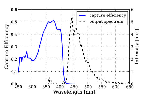
We have measured this quantity in a lab setup using a monochromator with wavelength range 250 – 1200 nm and two identical photo-sensors, read out via lock-in amplifiers. The emission spectrum and capture effiency as a function of wavelength are shown in Fig. 2 for the 20 mm sample described in the previous section. For the 5 mm sample, the results are identical within the precision of our measurement.
The peak efficiency of 50 % has to be compared to the theoretical maximum, which, assuming that all incoming photons are absorbed by the active dye and then re-emitted isotropically with 100 % quantum effiency, and ignoring any transport loss, is given by the fraction of solid angle where total internal reflection occurs:
| (2) |
The decrease in efficiency down to 20 % below 350 nm is assumed to be due to reabsorption and/or UV absorption inside the PVT base of the paint. This should be reducible by thinning the paint layer and future R&D for the dye. An improved production scheme allowing for thinner layers is under development.
3.2 PMT readout efficiency
To account for the fact that the captured photons coming out at either end of the wavelength-shifting glass tube will be read out by PMTs, its (normalized) output spectrum (also shown in Fig. 2) has to be convolved with the quantum efficiency of a realistic PMT. This gives the fraction of photons coming out of the wavelength-shifting tube that are actually detected by the PMT. Using the data provided by Hamamatsu for their R7600-EG prototype [5], we arrive at a readout efficiency of .
3.3 Angular efficiency
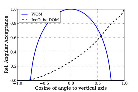
The angular acceptance of the WOM can be calculated with Fresnel’s equations. We assume a homogeneous, parallel bundle of light incident onto the WOM at an angle w.r.t. its longitudinal (i.e. vertical) axis. The acceptance at this angle is calculated by integrating the transmission probability from ice () through glass () into air () over the whole visible surface of the WOM, including the fact that the WOM appears shortened by a factor of at angles different from . Note that this only covers the propagation of photons from the surrounding ice into the air gap, since the penetration from air into the actual wavelength-shifting tube is included in the capture efficiency described in Sec. 3.1.
In Fig. 3 we show the relative acceptance with respect to the maximum for the WOM and an IceCube Digital Optical Module (DOM), the photosensor module used in IceCube [9]. For the WOM, a maximum acceptance is achieved at . Averaging the relative angular acceptance shown in Fig. 3 over all angles of incidence, the mean angular acceptances are and , respectively.
3.4 Full module efficiency

To obtain the detection efficiency of the fully assembled module, the three efficiencies discussed above, , , and , have to be multiplied:
| (3) |
The result, assuming optimal illumination (i.e. ), is shown in Fig. 4, compared to the efficiency of an IceCube DOM at its optimal illumination angle ().
4 Other properties
4.1 Noise
Two components of the WOM dominate its noise rate: the fused quartz glass tubes and the PMTs. Clearly, the pressure housing will contribute much more than the painted tube in the interior simply due to its larger mass.
The required thickness depends strongly on the total diameter. Assuming a diameter of 20 cm of the pressure housing, a wall strength of 2 cm should be sufficient. With the typical activity of 0.02 Bq/kg stated in [4], this translates to a noise rate of 1 Hz per m2 of sensitive area.
To read out the WLS painted tube in the interior, its ring-shaped end faces need to be projected onto single PMTs using adiabatic light guides, Winston cones or similar. Then a total PMT cathode area equal to the size of twice its end face (since each end will be equipped with a PMT) is needed. Since the inner tube can have very thin walls, this area should be at the order of tens of cm2. According to the numbers from [5, 6], this corresponds to a PMT noise rate below 10 Hz.
So assuming a WOM with a diameter of 20 cm and a length of 2 m, hence a sensitive area of , a total module noise rate in the order of only 10 Hz seems possible.
4.2 Time Resolution
Using a toy Monte Carlo, we have simulated the propagation of photons inside the wavelength-shifting tube. Since there is no possibility to reconstruct the point at which a detected photon actually entered the WOM, the variance of the full travel time distribution has to be considered for the time resolution of the module. This number is proportional to the length of the module with a value of 1.4 ns/m.
A similar contribution to the timing uncertainty arises from the fact that, in order to be detected, the photons have to be absorbed and re-emitted by one of the wavelength-shifting dye molecules. The typical emission time is stated by the manufacturer to be 2.0 ns [7].
5 Conclusion
Comparing the module efficiencies of WOM and IceCube DOM in Figs. 3 and 4, at first sight the WOM only provides a moderate improvement in photon collection efficiency. However, one has to keep two things in mind:
First, the WOM can be produced in a very large size since its size-critcal components are just two glass tubes (pressure vessel and WLS painted inner tube), that are easily scalable. The size of the DOM on the other hand is given by the size of the enclosed PMT which can hardly be pushed much further at reasonable cost222This is mostly due to the deployment in the antarctic glacier: Larger spherical DOMs need larger diameter drill holes, dramatically increasing the costs for drilling..
| Module | Eff. Area | Noise | ||
|---|---|---|---|---|
| WOM | 4.40 % | 57.5 % | 101 cm2 | 10 Hz |
| DOM | 5.36 % | 34.1 % | 12.9 cm2 | 800 Hz |
Second, the WOM is more sensitive in the UV below 370 nm. As the photons that are to be detected stem from Cherenkov radiation, their spectrum is proportional to . Accounting for this initial spectrum when calculating the mean module efficiency
| (4) |
the performance of the WOM improves significantly w. r. t. the IceCube DOM.
Assuming a WOM with a diameter of 20 cm and a length of 2 m as in Sec. 4.1 and, for comparison, a DOM with 30 cm diameter [9], convolving both with a Cherenkov spectrum between 250 and 600 nm, we can now calculate the full effective area of WOM and DOM for an isotropic flux. The results are shown in Tab. 1.
So in terms of total effective area,
| (5) |
one WOM with a cross-section of cm2 is the equivalent of about eight IceCube DOMs ( cm2). If one would reduce the considered wavelength range to 300 – 600 nm, the mean module efficiency increases by about 40 % for the DOM (since its “blind” regime below 300 nm does not enter in the calculation), while for the WOM it remains essentially constant.
In summary, our proposed concept offers a technological solution to obtain a large area single photon sensor with exceptionally low noise rate. Future work will concentrate on the optimization of the film coating, the choice of dyes, as well as on the proof of long term stability and large scale expandability.
Acknowledgments: We thank Christian Weinheimer for fruitful discussions. This work has been supported by the Helmholtz Alliance for Astroparticle Physics (HAP).
References
- [1] A. Achterberg et al. (IceCube Collaboration), Astropart. Phys. 26 (3) (2006) 155.
- [2] The Super-Kamiokande Collaboration, Nucl. Instrum. Meth. A501 (2003) 418.
- [3] S. Böser, M. Kowalski, L. Schulte, N. L. Strotjohann and M. Voge, arXiv:1304.2553.
- [4] Technical Glass Products Inc., Fused Quartz Properties, www.technicalglass.com.
- [5] Hamamatsu Corporation, private correspondence.
- [6] H. O. Meyer, Europhys. Lett. 89 (2010) 58001.
- [7] Eljen Technology, EJ-298 data sheet, www.eljentechnology.com/images/stories/Data_Sheets/Paints_Reflectors/EJ298%232%20data%20sheet.pdf.
- [8] Saint Gobain Crystals, Low level/low background counting, www.detectors.saint-gobain.com/document.aspx?docId=201358.
- [9] K. Hanson and O.Tarasova, Nucl. Instrum. Meth. A567 (1) (2006) 214.
- [10] M. G. Aartsen et al., Nucl. Instrum. Meth. A711 (2013) 73.