A Compact Thermal Heat Switch for Cryogenic Space Applications Operating near 100 K
Abstract
A thermal heat switch has been developed intended for cryogenic space applications operating around 100 K. The switch was designed to separate two pulse tube cold heads that cool a common focal plane array. Two cold heads are used for redundancy reasons, while the switch is used to reduce the thermal heat loss of the stand-by cold head, thus limiting the required input power, weight and dimensions of the cooler assembly. After initial evaluation of possible switching technologies, a construction based on the difference in the linear thermal expansion coefficients (CTE) of different materials was chosen. A simple design is proposed based on thermoplastics which have one of the highest CTE known permitting a relative large gap width in the open state. Furthermore, the switch requires no power neither during normal operation nor for switching. This enhances reliability and allows for a simple mechanical design. After a single switch was successfully built, a second double-switch configuration was designed and tested. The long term performance of the chosen thermoplastic (ultra-high molecular weight polyethylene) under cryogenic load is also analysed.
keywords:
Heat switch , Pulse tube cryocooler , CTE , Space Cryogenics , Reliability1 Introduction
In space technology, redundancy concepts are often used to minimize the impact of a single failure. For applications requiring cryocoolers this can be done in several ways [1]. Nowadays cryocoolers for space applications in the 77 K range are of the pulse-tube type combined with a flexure bearing compressor. Possible sources of failure in such a configuration are the control electronics and the compressor (e.g. coils, spring breakage, seals), and the pulse-tube cold head (e.g. gas leakage). Additionally, the cold head can suffer from a long term gas contamination by outgassing components in the compressor or cold head itself.
As part of a research project studying various redundancy concepts for satellite operations, a heat switch was developed including two cold heads (CH1 and CH2) mounted on a single focal plane array detector
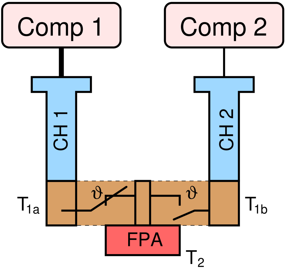
(FPA, see figure 1). The heat switch thermally connects an active cold head to the FPA while increasing the thermal contact resistance to a second cold head in stand-by mode, thus reducing the heat load of the stand-by system to the active cold head. In case of a failure of the active cold head, the stand-by cryocooler is turned on and the heat switch thermally disconnects the malfunctioning system while thermally connecting the now active redundant cryocooler. The switching is done automatically without need for external control or power.
There exist various kinds of heat switches for space applications, each having their own advantages and disadvantages. Most common are heat switches of the Gas-Gap and CTE-based (CTE: linear thermal coefficient of expansion) type [2, 3, 4], but also some designs based on other physical effects are known [5, 6]. In Gas-Gap switches the pressure of a gas in a small gap is controlled. This can be done e.g. by use of adsorbers or valves connected to gas reservoirs. The presence/absence of the gas in the small gap (typically 100 µm) enables/disables a thermal contact. The use of adsorbers is preferred for space applications as it enables passive switching. The design is somehow complicated because it involves the choice of a proper combination of gas sort, filling pressure, and adsorption material for a given temperature range. Especially for relatively high temperatures this can be challenging [7]. On the other side, this switch type does not contain any moving parts which may fail during the lifetime, e.g. because of wear or mechanical breakage.
The CTE-based switches rely on the thermal expansion of one or more components. In the most common mode of operation, a small gap separates two solids one of which has a high CTE compared to the other one. When the temperature decreases the high CTE material “shrinks” and closes the gap between the two solids. Below a certain “switching temperature”, the gap is fully closed, thus providing a heat conduction path. Further decrease in temperature increases the contact pressure and therefore lowers the thermal contact resistance. While the CTE-based switch is less complex compared to the gas-gap variant, it shares with it the disadvantage of requiring a relatively small gap in the order of several micrometers. However, by using thermoplastics with a high CTE, such as ultra-high molecular weight polyethylene (UHMW-PE), in order to circumvent the requirement of tiny gaps, the CTE-based switch becomes superior compared to other designs with respect to the required temperature range and standards for space applications. The aim of this work was to provide a proof of concept; so properties like minimum weight, high stability, and device integration, which are required for space applications, had a minor priority.
2 Thermal heat switch concept
Based on the design considerations outlined in the previous section, a CTE-based switch was chosen. Because the switch also needs to serve as a support for the FPA, the contact areas that are connected to the cold head and FPA must not move upon switching. As another requirement, the switch should exhibit an on-state thermal conductivity of more than 1 W/K at an operating temperature between 80-100 K and an off-state conductivity of less than 1 mW/K.
In many switches, the high-CTE component itself also acts as a thermal conductor. Unfortunately, high thermal conductivity materials, such as metals, exhibit a rather small CTE leading to a small gap sizes which require careful manufacturing and increase the risk of failure. Thermoplastics on the other hand, have a relatively high CTE compared to metals but a low thermal conductivity. This leads to a design where a thermoplastic is used as the switching element only, bringing two metals with high thermal conductivity into contact. Figure 2
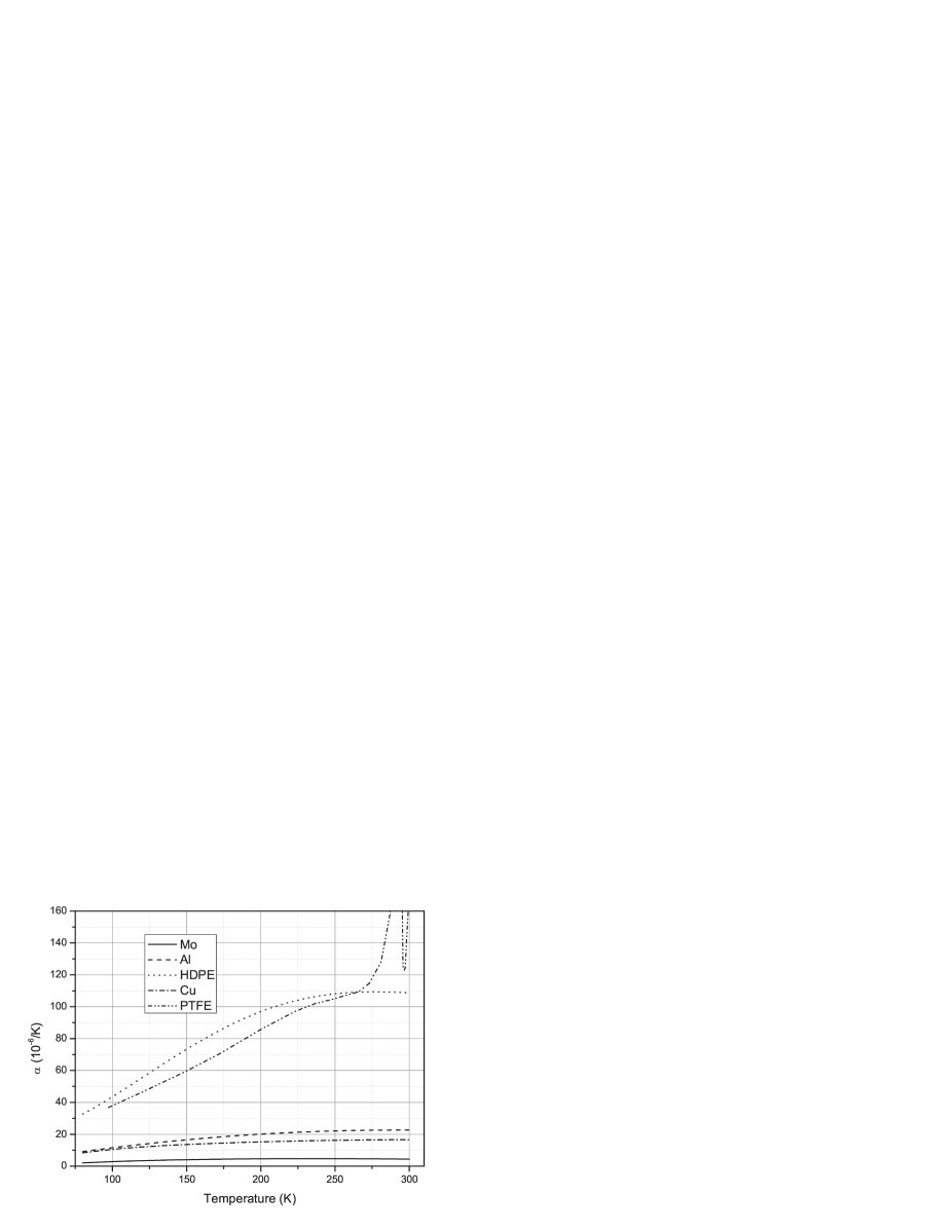
shows the CTE between 80 K and 300 K of some metals and thermoplastics; the data for metals were taken from the NIST database [8]. While most metals exhibit a CTE of 10-20, polytetrafluoroethylene (PTFE) for example has an order of magnitude higher CTE compared to copper at room temperature, but as for all polymers this strongly depends on the composition. PTFE shows two solid-solid phase transitions near room temperature with a maximum CTE of more than 500 [10]. Our measurements using liquid nitrogen revealed that ultra-high-molecular-weight polyethylene (UHMW-PE) has an even higher thermal contraction than PTFE between room temperature and 77 K, though we couldn’t find any CTE data for UHMW-PE at cryogenic temperatures. So we initially based our calculations on the HDPE (high-density polyethylene) CTE data from [9].
When designing a CTE-based switch, one important parameter is the gap width, which depends on the CTE material and the desired switching temperature. One has to take into account, that the standy-by cold head will cool down because of the finite off-state conductance. In our case, an off-state conductance of 1 mW/K would cool the stand-by cold head down to about 220 K. This means, that the switch needs to change state below this temperature. Otherwise the switch would also close on the stand-by side producing a thermal short. On the other hand, a high on-state switching temperature is desired to achieve a high contact pressure and thus a low thermal resistance. For HDPE, a CTE of
as extracted from the graph in Appendix 4A of [9] was used for calculations. The contraction in radial direction of the cylindrical switch (see figure 3b) is calculated by
where is the switching temperature and is the warm temperature at which the gap size is measured. is the inner radius of the UHMW-PE cylinder at room temperature. The copper shaft and jaws also shrink, but their shrinking was ignored in the initial gap calculations, since it is about an order of magnitude less than that of the UHMW-PE. Based on the considerations above, a gap width of 80 micrometers at room temperature was chosen. The remaining 50 microns which the UHMW-PE would additionally shrink from 200 K to the detector operating temperature of 100 K, if there will be no shaft, are turned into increased contact pressure. During the initial testing, the gap was adjusted several times to account for the higher CTE of UHMW-PE and the thermal expansion of the copper shaft and jaws.
Two switches were built: a single switch connected to a single cold head and heat load, which was used for initial testing. Later on, a second switch was built which has a T-form to connect two cold heads to a single load located in the middle of the switch. Figure

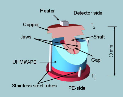
3a shows the sectional drawing and Figure 3b shows a 3D-model of the single, cylindrical switch design. The part connected to the heat load (detector side) consists of an inner shaft made of a solid copper cylinder (10 mm diameter) with a flange on one end. The part connected to the cold head (PE-side) consists of a copper flange with four integrated copper jaws that are separated from the inner cylinder by the gap. A non-enforced hollow UHMW-PE (virgin Tivar1000 from Quadrant PHS GmbH, Vreden, Germany) cylinder is put around the jaws to act as the high-CTE element. The two copper parts are hold together by four thin stainless steel tubes (Ø 2 mm, 150 µm wall thickness) which mainly determine the thermal off-state resistance. The total height of the switch is 30 mm.
The distribution of stress inside the switch components was calculated using Hooke’s law which can be found in textbooks. The contact pressure of the jaws to the shaft at 100 K was estimated to be 1.4 MPa, while the maximum tensile stress in the UHMW-PE was estimated to be 5 MPa. Figure
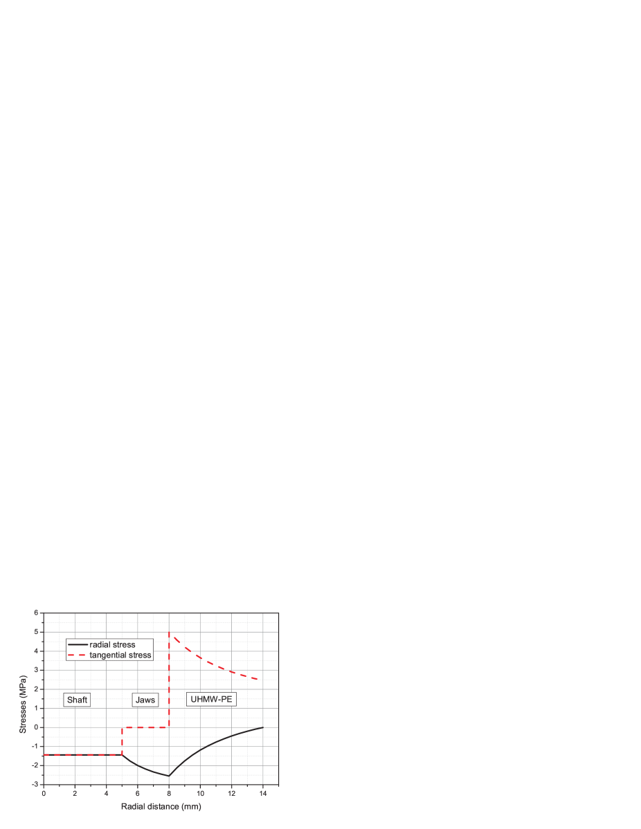
4 shows the compressive and tensile stresses in radial and tangential (= circumferential) directions inside the switch components, calculated at an operating temperature of 100 K. The axial stresses were omitted in the calculation.
3 Performance testing
The test apparatus consists of a coaxial pulse tube cold head driven by an AIM SL400 linear compressor [11] to which the single switch is attached. The detector side of the switch is equipped with an electrical heater. Pt100 temperature sensors are placed at the PE and the detector side of the switch, named and respectively (see figure 3b). For radiation shielding five layers of superinsulating foil are wound around the cold head and the switch.
The single switch was tested in several cool down/heat up cycles. Figure
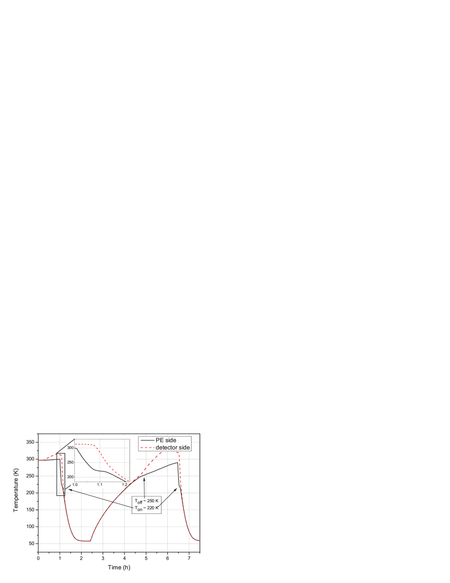
5 shows the switch in a single actuation cycle. During the measurement a constant heat load of 500 mW is being applied to the detector side of the switch. The inset in Figure 5 shows the cool down process to the closing temperature in detail. The detector side of the switch maintains a constant temperature until the switch closes at a temperature of about 220 K. After that, the detector side cools down quickly until it reaches the cold head temperature. From there on, both temperatures further decrease until the base temperature of 57 K is reached. At 2.5 hours the compressor is turned off. Both temperatures start to rise until the switch opening temperature of about 250 K is reached. From there on, the cold head temperature rises slower than the sensor temperature because of the low thermal coupling in the off-state. After 6 hours the heater is switched off and after around 6.5 hours the cooler and heater are started again and the next cycle begins. There exists a small hysteresis of about 25 K due to the lag of the UHMW-PE temperature with respect to the cold head temperature.
The close and open temperatures can be adjusted by the gap width between the copper shaft and the copper jaws. Increasing the gap by reducing the shaft diameter reduces the switching temperatures. Figure

6 illustrates the close and open temperatures of the switch for 11 cool down/heat up cycles and for two diameters of the shaft. The open symbols show the close/open temperatures for the switch with larger shaft diameter, where the gap was 20 µm smaller than that of the switch with smaller shaft diameter (solid symbols). Over the 11 open/close cycles, the switch temperatures are almost equal. If looking closely to the graph, a small tendency to lower temperatures with increasing cycle number can be seen, which can be attributed to creep of the UHMW-PE material (see section 4).
In order to measure the thermal conductance of the single switch, it was mounted in opposite direction with the detector side ( connected to the cold head while the heater was mounted at the PE-side () of the switch. In this way it is possible to also measure the off-state conductance at different stand-by cold head temperatures. During the on-state measurements, a constant heat load of 1 W is applied and the input power to the cold head is controlled so that the desired temperature is reached. The only exception is the point at = 200 K where the heat load was 7 W. The conductance is given by the ratio of the applied heat load and the temperature difference between the two sides of the switch (). For measuring the off-state conductance, the heater power is tuned in such a way that the switch is kept open while the detector side is cooled down to 80 K. Figure 7 shows the off-state conductance as function of temperature. The heating power was varied between 130 and 180 mW to keep the PE-side of the switch at the desired temperature. At a typical off-state operation point of 220 K, the conductance is around 2 mW/K. For higher temperatures, the off-state conductance increases because of the higher heat conductance of the stainless steel support tubes. For on-state measurements, the heater is switched off until the switch closes due to heat conduction losses over the stainless steel tubes. Once the switch is closed, the heater can be used to measure the thermal conductance. Figure

7 also shows the on-state conductance in a temperature range between 80 and 240 K. Due to the higher contact pressure at lower temperatures, the thermal conductance increases with decreasing temperature and consequently the temperature difference becomes smaller. For an operation point of 100 K, the thermal conductance in on-state is 1000 mW/K.
To test the mechanical stability, the switch with the smaller shaft diameter has undergone a shaker test at AIM GmbH (Heilbronn), where the switch was shaked at different frequencies with a 150 g mass mounted on the detector side. The test revealed several resonance points at which the two switch parts (jaws and shaft) clashed together. An optical inspection after the test confirmed this, but no hints of deformation could be seen. Figure

8 shows the open/close temperatures after the shaker test. Compared to the cyclic test in Figure 6 (solid symbols), the opening temperature dropped by about 13 K, while the closing temperature is nearly the same as before. In the measurements after the shaker tests, between cycle 8 and 9 the switch was heated up to 340 K, causing an unusual shift to higher open/close temperatures. The root cause of this is not yet understood. The thermal conductance measurements in Figure

9 show a decrease in on-state conductance to 600 mW/K at 100 K, while the off-state conductance increased to 8 mW/K after the shaker test. All measurements were done with 1 W of heating power. These results hint at a small deformation of the switch by the shaker test, which likely affects the heat conductance. Given that the switch was not yet optimized for mechanical stability, the results after the shaker test show that the present design using a large gap, compared to that of purely metallic CTE-based switches, can simplify heat switch manufacturing while maintaining a reliable switching function.
After successful tests with the single switch, we built a T-formed, double switch, which basically consists of two singles switches with a common detector side. The test apparatus was extended to include two pulse tube cold heads of the same type connected to the two PE-sides of the T-form switch. A heater and a temperature sensor () were installed at the common detector side, and two temperature sensors (, ) and two heaters were mounted on the PE-sides of the double switch.
The cycle test results of the double switch are shown in Figure 10. One of the coolers (cold head A) was started while the other was in stand-by. After reaching a temperature of = 100 K, the heater at the detector side was adjusted to maintain this temperature. The stand-by side also cools down a bit because of the small but non-zero off-state conductance of the switch. In general, the switch temperature in off-state is given by a balance between heat conduction along the switch and along the standby cold head. After the stand-by cold head B reached a stable temperature of 225 K, the active cold head A was turned off and the cold-head side of the switch was heated above the opening temperature again. Now the active and the stand-by cold head changed their function, and the cycle was repeated several times, as seen from Figure

10. Both sides of the switch are working as expected. The opening/close temperatures are nearly identical. The passive PE-side cools down to 225 K, which is only 25 K above the closing temperature of the switch. By further lowering the thermal conductance of the switch in off-state or reducing the heat leak through the stand-by cooler this temperature difference can be enlarged in future, as in the present lay-out it seems a bit low for long term operation.
4 Long term performance of UHMW-PE
For long term satellite missions it is essential to know how the materials used in the switch will degrade in their properties during mission lifetime. It is known that thermoplastics tend to creep over time, which would have a significant effect on the switch performance. Creep behaviour is influenced by many aspects of the actual material composition and treatment, so the results shown below should be handled with care. Material pre-aging can significantly reduce long term creep, whereas other methods like material-enforcement tend to reduce the CTE.
Long term creep measurements for UHMW-PE have been studied for room temperatures and above, mainly because of their application in the medical sector [12]. But creep data at cryogenic temperature ranges is not available in literature. We therefore built a test apparatus for testing the creep of our UHMW-PE samples at low temperatures using strain gauges (type Micro-Measurements EK-13-250BF-10C/W). The UHMW-PE samples were in form of a solid cube with an edge length of 20 mm. Figure
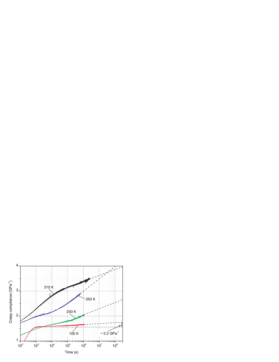
11 shows the compliance data under a compressive load of 1 MPa for several temperatures. Similar results are expected for tensile stresses. The compliance is defined as , where is the measured strain and is the applied pressure load. After some initial relaxation processes on a time scale of less than 10,000 s, it appears that the material starts to creep linearly on a logarithmic time scale. At least for the 100 K data this is in accordance with the work of Struik [13], who used short term measurements near room temperature to predict low temperature creep data for temperatures , where is the glass transition temperature of UHMW-PE. For a mission time of 10 years, a creep compliance of at 100 K can be roughly extrapolated. For a typical maximum internal stress of about 5 MPa (see figure 4), this would result in a strain of only 0.1%. When applied to our switch geometry, this corresponds to a decrease in contact pressure by about 12%.
5 Conclusions
A simple, compact, high reliability thermal heat switch for cryogenic space applications operating near 100 K based on the thermal expansion was built and tested. Two variants have been studied: a single and a double heat switch configuration. The single switch showed a state change around 220 K, and an on/off-state conductivity of more than 1 W/K and an 3 mW/K respectively. After shaker tests the performance decreased a bit, but the switching function was not affected.
The double switch was successfully tested in a two cooler configuration and showed reliable switching characteristics over several cycles. The switching temperatures as well as the on/off state conductivity was similar to the single switch design.
UHMW-PE, which was used as the high CTE material, shows a rather high creep rate under uniaxial pressure at room temperature. To estimate the degeneration of the material during switch operation at cryogenic temperatures, creep tests were performed and extrapolated for long term prediction. At 100 K, the compliance is estimated to be in 10 years resulting in a 12% drop in contact pressure during on-state.
The CTE-based thermal switch presented in this paper is a promising concept. Further development will focus on mechanical properties as stability and weight. The long term creep of the UHMW-PE CTE material also needs a more thorough investigation.
Acknowledgements
This work was financially supported by the German Federal Ministry of Economics and Technology (grant no. 50EE0940). The authors thank AIM Infrared Modules (Heilbronn) for performing the shaker tests and Frank Schmülling (DLR Bonn) for useful discussions.
References
- Ross Jr [2002] R.G. Ross Jr. Cryocooler Reliability and Redundancy Considerations for Long-Life Space Missions. In Proceedings of the 11th International Cryocooler Conference, pages 637–648, 2002. doi: 10.1007/0-306-47112-4\_79.
- Chan and Ross [1990] C. K. Chan and R. G. Ross. Design and Application of Gas Gap Heat Switches, Final Report of Phase II. Technical Report NASA-CR-187339, National Aeronautics and Space Administration, Washington, DC, 1990.
- Marland et al. [2004] B. Marland, D. Bugby, and C. Stouffer. Development and testing of an advances cryogenic thermal switch and cryogenic therma switch test bed. Cryogenics, 44(6-8):413–420, 2004. doi: 10.1016/j.cryogenics.2004.03.014. 2003 Space Cryogenics Workshop.
- Wang et al. [2007] W. Wang, L. Yang an T. Yan, J. Cai, and J. Liang. Development of a Cryogenic Thermal Switch. In S. D. Miller and Jr. R. G. Ross, editors, Cryocoolers 14, pages 589–594, 2007.
- Prenger et al. [1994] F.C. Prenger, W.F. Stewart, and J.E. Runyan. Development of a cryogenic heat pipe. In Peter Kittel, editor, Advances in Cryogenic Engineering, volume 39 of Advances in Cryogenic Engineering, pages 1707–1714. Springer US, 1994. ISBN 978-1-4613-6074-2. doi: 10.1007/978-1-4615-2522-6\_209.
- You et al. [2005] J. G. You, D. P. Dong, W. Y. Wang, and Z. W. Li. Development and testing of a novel thermal switch. In Proceedings of the 20th ICEC, pages 423–426. Elsevier Ltd., 2005.
- Catarino et al. [2008] I. Catarino, G. Bonfait, and L. Duband. Neon gas-gap heat switch. Cryogenics, 48:17–25, 2008. doi: 10.1016/j.cryogenics.2007.09.002.
- NIST Cryogenics Technologies Group [2013] NIST Cryogenics Technologies Group. Material properties data base. Internet address, 2013. URL $http://www.nist.gov/mml/acmd/structural_materials/cryogenicmatprop.cfm$. Accessed June 1.
- Hartwig [1994] Günther Hartwig. Polymer properties at room and cryogenic temperatures. Plenum Publishing Corporation, New York, 1994.
- Kirby [1956] Richard K. Kirby. Thermal Expansion of Polytetrafluoroethylene (Teflon) From -190∘ to +300∘. Journal of Research of the National Bureau of Standards, 57(2):91–94, 1956. doi: 10.6028/jres.057.010.
- Yang and Thummes [2005] L. W. Yang and G. Thummes. Development of Stirling-Type Coaxial Pulse Tube Cryocoolers. In Ronald G. Ross, editor, Cryocoolers 13, pages 141–148. Springer US, 2005. ISBN 978-0-387-27533-8. doi: 10.1007/0-387-27533-9\_20.
- Deng et al. [1998] Meng Deng, Robert A. Latour, Amod A. Ogale, and Shalaby W. Shalaby. Study of creep behavior of ultra-high-molecular-weight polyethylene systems. Journal of Biomedical Materials Research, 40(2):214–223, 1998. doi: 10.1002/(SICI)1097-4636(199805)40:2<214::AID-JBM6>3.0.CO;2-O.
- Struik [1989] L. C. E. Struik. Mechanical behaviour and physical ageing of semi-crystalline polymers: 3. Prediction of long term creep from short time tests. Polymer, 30(5):799–814, 1989. doi: 10.1016/0032-3861(89)90176-6.