Probing the anharmonicity of the potential well for magnetic vortex core in a nanodot
Abstract
The anharmonicity of the potential well confining a magnetic vortex core in a nanodot is measured dynamically with a Magnetic Resonance Force Microscope (MRFM). The stray field of the MRFM tip is used to displace the equilibrium core position away from the nanodot center. The anharmonicity is then inferred from the relative frequency shift induced on the eigen-frequency of the vortex core translational mode. An analytical framework is proposed to extract the anharmonic coefficient from this variational approach. Traces of these shifts are recorded while scanning the tip above an isolated nanodot, patterned out of a single crystal FeV film. We observe % increase of the eigen-frequency when the equilibrium position of the vortex core is displaced to about one third of its radius. This calibrates the tunability of the gyrotropic mode by external magnetic fields.
There has been recently a renewed interest, both theoretical and experimental, in the problem of nonlinear (NL) magnetization dynamics inside confined nanostructures Slavin2009 . NL phenomena are responsible for the creation of novel dynamical objects Mohseni2013 , analogs of dynamical solitons. They also set the figure of merit of spintronics devices, e.g. the spectral purity and tuning sensitivity of spin transfer torque nano-oscillators Slavin2009 . On the theoretical side, predictions on the amplitude of the NL coefficients have been found to be extremely difficult to compute beyond the uniformly magnetized ground state. The difficulty raises both from the magneto-dipolar field, which introduces a non-local interaction, and from the kinetic part of the effective field (or gauge field), which modifies the texture of the magnetic configuration. On the experimental side, the most promising findings have been discovered on non-uniform ground states, such as magnetic vortex existing in ferromagnetic nanodot. Vortices have stimulated the emergence of higher performance microwave oscillators using isolated Pribiag2007 or dipolarly coupled Locatelli2011 nanodot, or for future magnetic memories by allowing the resonant switching of the magnetic configuration Pigeau2010 .
Magnetic vortex corresponds to a curling in-plane magnetization spatial distribution leaving a nanometric in size core region ( the exchange length), where the magnetization is pointing out-of-plane. The lowest energy mode is a translational (or gyrotropic) mode of the vortex core position , expressed here in reduced unit of the dot radius. Its properties are governed by the magnetostatic potential well in which the core evolves. For a circular nanodot, the magnetostatic energy is isotropic in the dot plane and it can be written as a series expansion of even powers of the dimensionless Dussaux2012 :
| (1) |
At the present, only the parabolicity of the confinement, , has been well characterized experimentally and the measured value is in agreement with theoretical predictions Novosad2005 . This is not the case for the higher order terms and there is no consensus yet on the order of magnitude or the sign of the anharmonic coefficient afferent to the depolarisation effect of a displaced vortex inside a large planar circular nanodot. The asymptotic limit of large radius is the relevant aspect ratio to test the dipole dominating limit and the circular symmetry is necessary to avoid the additional complexity of non-isotropic potential found for example in square shaped elements Drews2012 . Up to now, attempts to measure in circular nanodot using large rf excitation have so far lead to inconsistent results between experiments Pigeau2011 (red shift) and theory Gaididei2010 (blue shift). The measurement of through a variational approach, consisting in studying the small change of oscillation period when a large static displacement of the vortex core equilibrium position is produced, has so far failed too: this counterpart of large rf oscillation has mostly revealed the potential well inhomogeneities leading to pinning of the core Chen2012 ; Burgess2013 .
In this work, we report on an experimental measurement of in a large planar circular nanodot using a Magnetic Resonance Force Microscope (MRFM). All the experimental measurements are performed on an individual nanodisk of thickness nm thick and nominal radius nm, patterned out of a single crystal FeV film. Only the perfect crystalline structure ensures an unpinned displacement of the vortex core throughout the sample volume. We rely here on the non-uniform stray field of the magnetic tip of the MRFM to displace the vortex core away from the nanodot center. The anharmonic coefficient is then inferred from the measurement of the relative variation of the eigen-frequency of the gyrotropic mode as a function of the tip displacement.
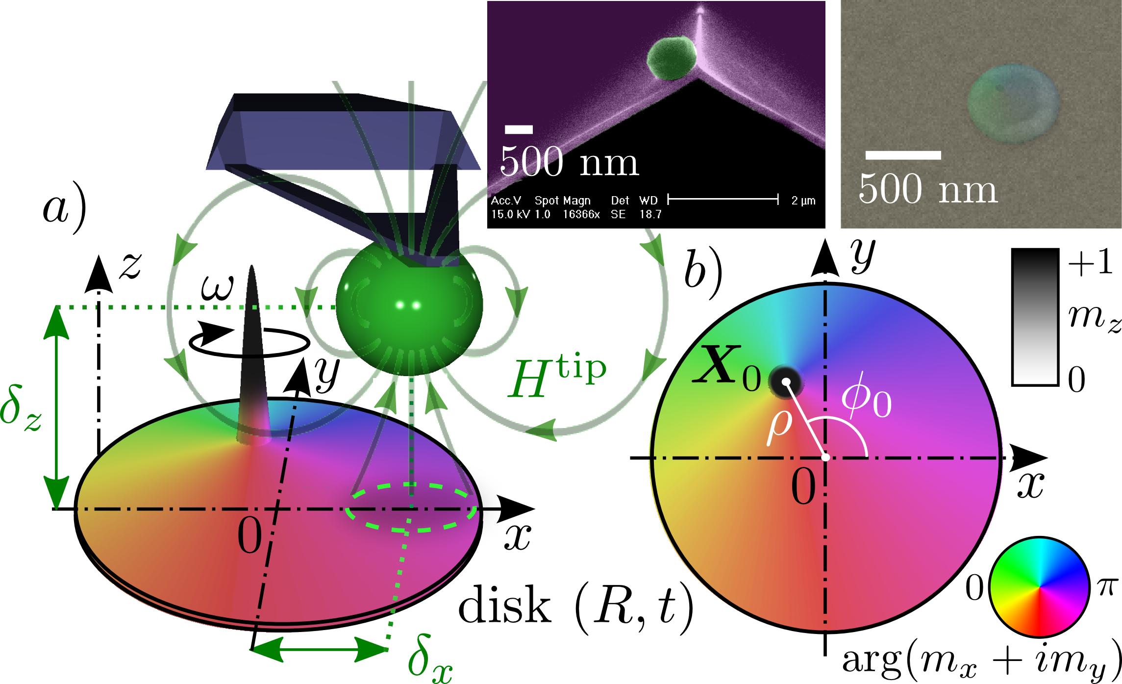
We start first with a description of the experimental setup Klein2008 (FIG.1). The right inset shows an image of the sample: a circular nanodot, which is patterned by standard lithography and ion-milling techniques from an extended film of Fe-V (10% V)Mitsuzuka2012 with magnetization kG. A magnetic tip is brought in the vicinity of the sample (left image). The tip consists of a soft Fe particle glued at the apex of micro-cantilever. The MRFM is placed inside a superconducting coil magnet, which produces an homogenous bias magnetic field of 6 kOe along the -direction (parallel to the normal of the disk). The value of is chosen to be strong enough to magnetize the MRFM tip close to its saturation value, while remaining weak enough compared to the saturation field of the nanodot to preserve the vortex ground state inside the sample. At the tip stray field is , the dipolar field generated by a point magnetic moment emu oriented along Pigeau2012 . Effects of perpendicular magnetic field on magnetic vortex are well established Ivanov2002 ; Loubens2009 : the in-plane spins are tilted towards the applied field producing hereby a decrease 111At kOe, the spins are tilted out-of-plane by about 20∘ generating a 7% decrease of the in-plane component of the magnetization outside the vortex core. of the in-plane component of the magnetization outside the vortex core (cone state Ivanov2002 ).
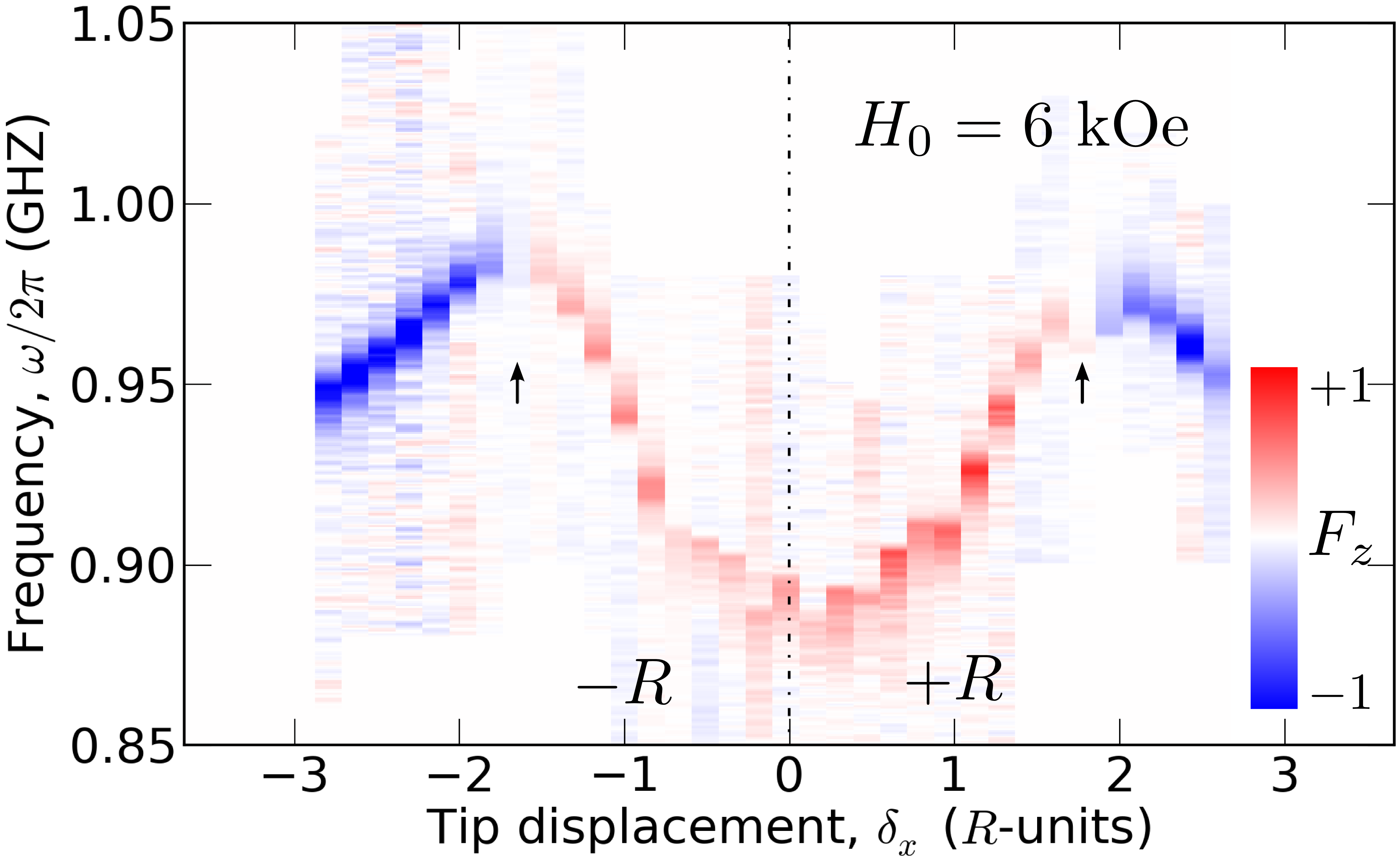
We then proceed to the measurement of the variation of the excitation spectrum of the gyrotropic mode when the tip is scanned by m along the -direction by steps of 50 nm (see FIG.2). The scan height is m 222Although the use of piezo-actuators allows ultra-precise displacement of the micro-cantilever, the value of has inherently some uncertainty as it corresponds to the free axis of the cantilever. above the nanodot or in reduced units of (hereafter all spatial displacements are expressed in units of the dot radius .) Placing the tip at the origin ( or on the axis of the disk), attracts the vortex core at the center of the nanodot. From there, lateral displacement of the magnetic tip produces a vector shift of the vortex core equilibrium position from the dot center. The process is driven by the growth of the in-plane domain parallel to the in-plane component of the tip stray field. We observe in FIG.2 that the eigen-frequency increases (blue shift) upon increasing . Noting that the frequency shift is symmetric and isotropic (the signature that the intrinsic potential is being probed) we find that the vortex core dynamics can be tuned on a relative large range ( 10%), hereby demonstrating that the magnetostatic potential must be anharmonic, since a purely parabolic shape would have lead to a frequency independent behavior on .
Analysis of the amplitude of the MRFM signal gives a hint on the amount of displacement achieved during a scan. The MRFM signal corresponds to the difference of vertical force acting on the cantilever when the vortex motion is excited. Defining the reduced magnetization vector, the gyromotion produces a diminution of the spontaneous magnetization along the local equilibrium direction , that mostly occurs outside the core region Guslienko2008a . The generated force can be then calculated from the reaction force acting on the nanodot due to the gradient tensor of the tip: . Cartesian tensor notation is used here, with repeated indices being assumed summed. The chevron bracket indicates that the enclosed quantity is averaged over the volume of the nanodot. The red-blue colormap in FIG.2 codes the amplitude MRFM signal: red (blue) means attractive (repulsive) force. Small arrows at indicate the compensation point of the force: where the change of sign occurs. This distance is about twice smaller than the one required to change the sign of the force in the saturated state (contribution dominated by ). The difference is interpreted as due to the translation of the core position transversally to the tip position (along the -axis). The growth of this domain generates a repulsive vertical force on the tip trough the cross gradient term . We shall thus use the position of the compensation point to calibrate precisely the amplitude of the displacement of the vortex core.
Our next step is to develop an analytical framework allowing the extraction of from this variational study. The first stage of this analysis is to calculate the equilibrium position (here and are the two in-plane cartesian coordinates) by minimizing the total energy , the sum of , the magnetostatic self-energy of the vortex ground state which confines the vortex core to the center of the nanodot and , the Zeeman energy which represents the interaction with the external magnetic field and is responsible for the displacement . The magnetic configuration inside the nanodot is conveniently described by a conformal mapping of the complex variable ( indicating the complex conjugate), which is a piecewise function of the complex position with outside the vortex core region and inside. The function captures the texture of the spatial configuration. To calculate the new equilibrium position , it is appropriate to describe the dot magnetization, , by the rigid vortex model (RVM) Guslienko2001 , written as . Here denotes the core radius in reduced unit of and the sign depends on the chirality of the vortex. The static displacement is then obtained by minimizing the total energy 333All energies can be approximately calculated by running the integrand solely on the nanodot volume outside the vortex core region. with the analytical expression of obtained by the RVM. In the RVM, the magnetostatic energy is generated by the surface magnetic charges located at the circumference of the disk (the volume charges are absent). The confinement potential follows from the integral where the integration is taken over the disk periphery and is given by:
| (2) |
is the azimuthal direction of the vortex equilibrium position measured from the averaged in-plane bias field direction (here -axis).
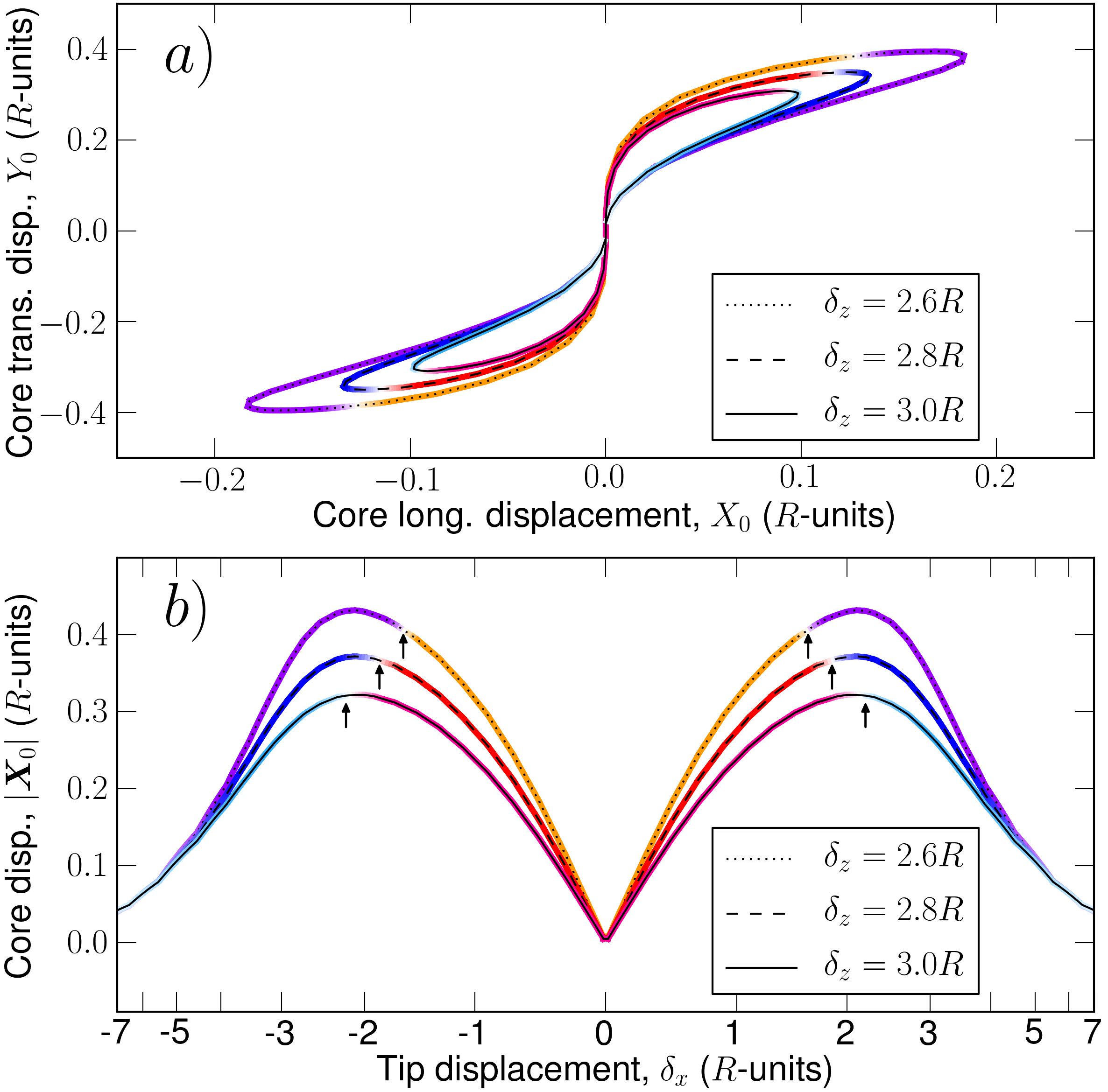
The implicit trajectory of is shown in FIG.3a for three different heights around the nominal value. As expected the in-plane components of the tip magnetic field displace the vortex core mainly along the -axis. The displacement along -axis is approximately twice smaller. The resulting displacement distance as a function of is shown in FIG.3b. We use here a skewed scale on the abcisse to show the behavior when . We have also calculated the corresponding dipolar force produced on the tip. The result is coded in the colormap using the same convention as in FIG.2. We have placed small arrows at the compensation points. Since decreasing the scan height increases the amplitude of , we find that the position of the arrows sensitively depends on . Varying in the experimental error bars displaces the compensation point by (or nm) around the mean value , in agreement with the experimental data. We shall use this marker to evaluate the uncertainty window of in our experiment.
The second stage of this analysis is to perform a linearization of the vortex equation of motion to a cyclic excitation field. The instantaneous response is decomposed into the static component , calculated previously, and a dynamic component representing the small oscillating deviation of the vortex core position from its equilibrium 444We estimate that in our experiment, where the microwave field strength is Oe.. In the dynamical case, the dipolar pinning imposes a precession node at the dot circumference Guslienko2008a . It implies that the dynamical magnetization comes from the variation, , of a magnetic configuration that has no radial component at the dot border. Therefore, to calculate the frequency of the small dynamic vortex displacement , it is appropriate to use the surface charges free model or two vortex ansatz (TVA) written as Guslienko2002 with . In our notation, the dampingless Thiele equation simply writes , where is the total energy and is the gyrovector Guslienko2008 (the dot is the short hand notation for the time derivative and is the gyromagnetic ratio). Linearization around yields the gyrotropic angular frequency
| (3) |
being the stiffness of the vortex core to small displacements in both the and directions. Distinction between different cartesian directions is necessary once the trajectory becomes elliptical. This is precisely, what occurs when : the amplitude of the -component along differs from the amplitude of the -component perpendicular to (short axis of the ellips is along the radial direction). The degree of ellipticity is determimed by the anharmonic contribution . This is in contrast to the opposite limit , where the trajectory corresponds to a large amplitude circular vortex core motion around the nanodot center Dussaux2012 .
To calculate the different tensor elements of the stiffness , one must decompose it in two contributions corresponding respectively to the magnetostatic and Zeeman energies. The first order value of the TVA magnetostatic stiffness, , has been already expressed analytically Guslienko2006 . The analytical expression of the anharmonic correction is obtained by inserting Eq.(1) in Eq.(3) and it leads to a simplified expression . It turns out that the Zeeman stiffness can be neglected. Indeed, it can be shown that the tip stray field produces no Zeeman stiffness along the diagonal elements (). Only the cross-terms are non-vanishing but they represent a negligible correction ( 3%). We thus find that at and , Eq.(3) simplifies to the well known expression Guslienko2002 . At and , the stiffness of the magnetostatic potential is renormalized by the in-plane magnetization projection of the cone state and one obtains Loubens2009 . In the general case and , the relative frequency shift reduces to the following analytical expression:
| (4) |
Notice that the prefactor of 2 multiplying is specific to the limit .
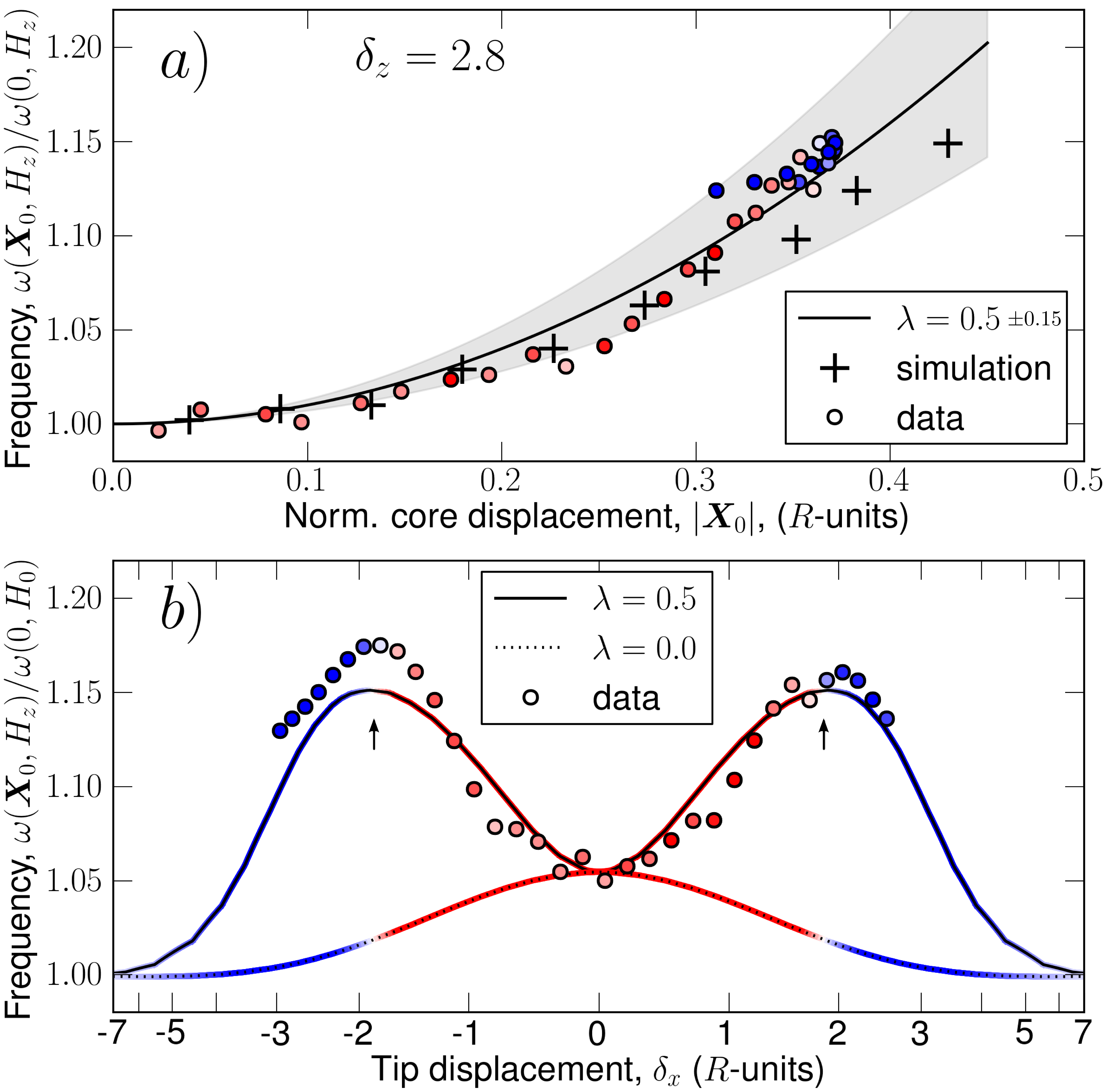
The next step is to plot in FIG.4a the experimental data extracted from FIG.2, renormalized by the predicted dependence of , as a function of the calculated during a lateral scan of the tip at fixed . Fitting the data of FIG.4a with a parabola (solid line) yields an average curvature . We have plotted in FIG.4b the experimentally measured relative frequency normalized by . The latter quantity is inferred experimentally by studying the decay of upon increasing , while keeping the tip on the symmetry axis (): a fit of the decay behavior yields the asymptotic value . In FIG.4b, the data point are colored according to the colormap associated with the amplitude of the force. For comparison, we have also plotted the predicted variation of by Eq.(4) as a function of for two values of . Setting in Eq.(4), would have produced the usual bell-shaped curve Pigeau2012 , which corresponds to a diminution of when the tip moves away from the nanodot axis. The behavior for is in excellent agreement with the experimental data, both in the amplitude of the NL frequency shift and in the position of the compensation point of the force.
We have then repeated the analysis by varying in the experimental error bar range: around the nominal value. Fit of the data by a parabola would lead to larger (smaller) values of depending if the amplitude of the shift decreases (increases). This procedure yields an uncertainty window of 30% for the determination of , shown as a shaded area in FIG.4a. Our fitting analysis did not account for higher order corrections in Eq.(1). In FIG.4a, the curvature increases with the displacement distance. Inclusion in the fit of terms in would have decrease the value of by about one standard deviation. As an additional check, we have performed a simulation of the expected for our nanodot using a mesh-size of 2.3 nm and a GPU-accelerated micromagnetic code Vansteenkiste2011a . The result is shown as crosses in FIG.4a, demonstrating that our determination of is in quantitative agreement with numerical simulations. It is also in agreement with the result obtained by Dussaux et al. from micromagnetic simulations performed in the limit on a thinner dot with approximately the same radius Dussaux2012 .
In summary, using an MRFM, we have measured quantitatively the anharmonicity coefficient produced by the depolarisation field of a vortex in a planar nanodot 555A recent preprint posted during the review process reports a new analytical expression for compatible with our measurement Metlov2013 . From a fundamental perspective, it is interesting to note that the obtained value (dipole-dominated) is about twice smaller than the predicted by the local easy-plane model Ivanov1998 . Further work is required to check if the value is independent of the out-of-plane external magnetic field or the dot aspect ratio, , in particular around the line of the vortex state stability Guslienko2008 . Finally, we mention that foldover experiments performed on the same nanodot at produce a red shift of the gyrotropic frequency (regime ), which is opposite with respect of the sign of . This finding suggests that the NL frequency shift observed in the foldover of the resonant curve is not dominated by the anharmonicity of the magnetostatic potential, but perhaps by the NL damping Pigeau2011 .
Acknowledgements.
This research was partly supported by the EU grant MOSAIC (ICT-FP7-317950), the French ANR Grant MARVEL (ANR-2010-JCJC-0410-01), the Spanish MEC Grants PIB2010US-00153 and FIS2010-20979-C02-01. S.S., K.G. and O.S. acknowledge support from the Marie Curie grant AtomicFMR (IEF-301656), from the IKERBASQUE and from the UPV/EHU, respectively.References
- (1) A. Slavin and V. Tiberkevich, Ieee Transactions On Magnetics 45, 1875 (Apr. 2009)
- (2) S. M. Mohseni, S. R. Sani, J. Persson et al., , Science 339, 1295 (Mar. 2013)
- (3) V. S. Pribiag, I. N. Krivorotov, G. D. Fuchs, P. M. Braganca, O. Ozatay, J. C. Sankey, D. C. Ralph, and R. A. Buhrman, Nature Physics 3, 498 (Jul. 2007),
- (4) N. Locatelli, V. V. Naletov, J. Grollier, G. de Loubens, V. Cros, C. Deranlot, C. Ulysse, G. Faini, O. Klein, and A. Fert, Applied Physics Letters 98, 062501 (Feb. 2011)
- (5) B. Pigeau, G. de Loubens, O. Klein, A. Riegler, F. Lochner, G. Schmidt, L. W. Molenkamp, V. S. Tiberkevich, and A. N. Slavin, Applied Physics Letters 96, 132506 (Mar. 2010)
- (6) A. Dussaux, A. V. Khvalkovskiy, P. Bortolotti, J. Grollier, V. Cros, and A. Fert, Physical Review B 86, 014402 (Jul. 2012)
- (7) V. Novosad, F. Y. Fradin, P. E. Roy, K. S. Buchanan, K. Y. Guslienko, and S. D. Bader, Phys. Rev. B 72, 024455 (Jul 2005),
- (8) A. Drews, B. Krüger, G. Selke, T. Kamionka, A. Vogel, M. Martens, U. Merkt, D. Möller, and G. Meier, Phys. Rev. B 85, 144417 (Apr 2012),
- (9) B. Pigeau, G. de Loubens, O. Klein, A. Riegler, F. Lochner, G. Schmidt, and L. W. Molenkamp, Nature Physics 7, 26 (Jan. 2011)
- (10) Y. Gaididei, V. P. Kravchuk, and D. D. Sheka, International Journal of Quantum Chemistry 110, 83 (Jan. 2010)
- (11) T. Y. Chen, M. J. Erickson, P. A. Crowell, and C. Leighton, Phys. Rev. Lett. 109, 097202 (Aug 2012),
- (12) J. A. J. Burgess, A. E. Fraser, F. F. Sani, D. Vick, B. D. Hauer, J. P. Davis, and M. R. Freeman, Science 339, 1051 (2013),
- (13) O. Klein, G. de Loubens, V. V. Naletov, F. Boust, T. Guillet, H. Hurdequint, A. Leksikov, A. N. Slavin, V. S. Tiberkevich, and N. Vukadinovic, Physical Review B 78, 144410 (Oct. 2008)
- (14) K. Mitsuzuka, D. Lacour, M. Hehn, S. Andrieu, and F. Montaigne, Applied Physics Letters 100, 192406 (May 2012)
- (15) B. Pigeau, C. Hahn, G. de Loubens, V. V. Naletov, O. Klein, K. Mitsuzuka, D. Lacour, M. Hehn, S. Andrieu, and F. Montaigne, Phys. Rev. Lett. 109, 247602 (Dec 2012),
- (16) B. A. Ivanov and G. M. Wysin, Phys. Rev. B 65, 134434 (Mar 2002),
- (17) G. de Loubens, A. Riegler, B. Pigeau, F. Lochner, F. Boust, K. Y. Guslienko, H. Hurdequint, L. W. Molenkamp, G. Schmidt, A. N. Slavin, V. S. Tiberkevich, N. Vukadinovic, and O. Klein, Physical Review Letters 102, 177602 (May 2009)
- (18) At kOe, the spins are tilted out-of-plane by about 20∘ generating a 7% decrease of the in-plane component of the magnetization outside the vortex core.
- (19) Although the use of piezo-actuators allows ultra-precise displacement of the micro-cantilever, the value of has inherently some uncertainty as it corresponds to the free axis of the cantilever.
- (20) K. Y. Guslienko, A. N. Slavin, V. Tiberkevich, and S.-K. Kim, Phys. Rev. Lett. 101, 247203 (Dec 2008),
- (21) K. Y. Guslienko, V. Novosad, Y. Otani, H. Shima, and K. Fukamichi, Phys. Rev. B 65, 024414 (Dec 2001),
- (22) All energies can be approximately calculated by running the integrand solely on the nanodot volume outside the vortex core region.
- (23) We estimate that in our experiment, where the microwave field strength is Oe.
- (24) K. Y. Guslienko, B. A. Ivanov, V. Novosad, Y. Otani, H. Shima, and K. Fukamichi, Journal of Applied Physics 91, 8037 (May 2002)
- (25) K. Y. Guslienko, Journal of Nanoscience and Nanotechnology 8, 2745 (Jun. 2008)
- (26) K. Y. Guslienko, X. F. Han, D. J. Keavney, R. Divan, and S. D. Bader, Physical Review Letters 96, 067205 (Feb. 2006)
- (27) A. Vansteenkiste and B. Van de Wiele, Journal of Magnetism and Magnetic Materials 323, 2585 (Nov. 2011)
- (28) A preprint posted on arXiv during the review process reports a new analytical expression for compatible with our measurement Metlov2013
- (29) B. A. Ivanov, H. J. Schnitzer, F. G. Mertens, and G. M. Wysin, Phys. Rev. B 58, 8464 (Oct 1998),
- (30) K. L. Metlov, ArXiv e-prints(Aug. 2013), arXiv:1308.0240 [cond-mat.mes-hall]