Superdirective dielectric nanoantennas with effect of light steering
Abstract
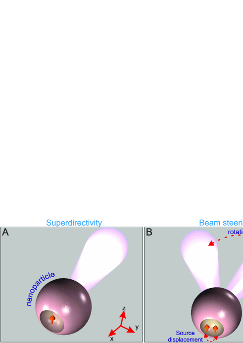
We introduce a novel concept of superdirective antennas based on the generation of higher-order optically-induced magnetic multipole modes. All-dielectric nanoantenna can be realized as an optically small spherical dielectric nanoparticle with a notch excited by a point source (e.g. a quantum dot) located in the notch. The superdirectivity effect is not associated with high dissipative losses. For these dielectric nanoantennas we predict the effect of the beam steering at the nanoscale characterized by a subwavelength sensitivity of the beam radiation direction to the source position. We confirm the predicted effects experimentally through the scaling to the microwave frequency range.
Introduction. Similar to conventional antennas, a nanoantenna converts a localized electromagnetic field into freely propagating light, and vice versa Lippitz10 ; Hulst2010 ; Novotny_10_NatPhot ; Hecht_obz_12 . For optical wireless circuits on a chip, nanoantennas are required to be both highly directive and compact AluWireless ; Hecht_obz_12 ; Landesa . In nanophotonics, directivity has been achieved for arrayed plasmonic antennas utilizing the Yagi-Uda design Novotny_10_NatPhot ; Giessen11 ; Hecht_obz_12 ; KrasnokOE ; Chew12 , large dielectric spheres Bonod10 , and metascreen antennas Eleftheriades . Though individual elements of these arrays are optically small, the overall size of the radiating systems is larger than the radiation wavelength . In addition, small plasmonic nanoantennas possess weak directivity close to the directivity of a point dipole Jain ; He ; Rodriguez .
Recently, it was suggested theoretically and experimentally to employ magnetic resonances of high-index dielectric nanoparticles for enhancing the nanoantenna directivity Krasnok_APL_12 ; KrasnokOE ; BonodOE . High-permittivity nanoparticles can have nearly resonant balanced electric and magnetic dipole responses Krasnok_11 ; KrasnokOE ; Evlyukhin ; Kuznetsov ; Lukyanchuk13 ; BonodOE . This balance of the electric and magnetic dipoles oscillating with the same phase allows the practical realization of the Huygens source, an elementary emitting system with a cardioid pattern Balanis ; Krasnok_11 ; Krasnok_APL_12 ; KrasnokOE and with the directivity larger than 3.5. Importantly, a possibility to excite magnetic resonances leads to the improved nanoantenna directional properties without a significant increase of its size.
Superdirectivity has been already discussed for radio-frequency antennas, and it is defined as directivity of an electrically small radiating system that significantly exceeds (at least in 3 times) directivity of an electric dipole Balanis ; Hansen ; Collin . In that sense, the Huygens source is not superdirective. In the antenna literature, superdirectivity is claimed to be achievable only in antenna arrays by the price of ultimately narrow frequency range and by employing very precise phase shifters (see, e.g., Ref. Balanis ; Hansen ; Collin ). Therefore, superdirective antennas, though very desirable for many applications such as space communications and radioastronomy, were never demonstrated and implemented for practical applications.
Superdirectivity was predicted theoretically for an antenna system Eleftheriades where some phase shifts were required between radiating elements to achieve complex shapes of the elements of a radiating system which operates as an antenna array. In this paper, we employ the properties of subwavelength particles excited by an inhomogeneous field with higher-order magnetic multipoles. We consider a subwavelength dielectric nanoantenna (with the size of 0.4 ) with a notch resonator excited by a point-like emitter located in the notch. The notch transforms the energy of the generated magneto-dipole Mie resonance into high-order multipole moments, where the magnetic multipoles dominate. This system is resonantly scattering i.e. it is very different from dielectric lenses and usual dielectric cavities which are large compared to the wavelength. Another important feature of the notched resonator is huge sensitivity of the radiation direction to a spatial position of the emitter. This property leads to a strong beam steering effect and subwavelength sensitivity of the radiation direction to the source location. The proposed design of superdirective nanoantennas may also be useful for collecting single-source radiation, monitoring quantum objects states, and nanoscale microscopy.
In order to achieve superdirectivity, we should generate subwavelength spatial oscillations of the radiating currents Balanis ; Hansen ; Collin . Then, near fields of the antenna become strongly inhomogeneous, and the near-field zone expands farther than that of a point dipole. This results in a growth of the effective antenna aperture which is associated with the maximum of directivity , being defined as , where is the wavelength of radiation in free space, and are the maximum power in the direction of the radiation pattern and the total radiation power, respectively. Normalizing the effective aperture S by the geometric aperture for a spherical antenna , we obtain the definition of superdirectivity in the form Hansen ; Balanis :
Practically, the value is sufficient for superdirectivity of a sphere. In this work, maximum of 6.5 for is predicted theoretically for the optical frequency range, and the value of 5.9 is demonstrated experimentally for the microwave frequency range.
All–dielectric superdirective optical nanoantennas.– Here we demonstrate a possibility to create a superdirective nanoantenna without hypothetic metamaterials and plasmonic arrays. We consider a silicon nanoparticle, taking into account the frequency dispersion of the dielectric permittivity Palik . The radius of the silicon sphere is equal in our example to nm. For a simple sphere under rather homogeneous (e.g. plane-wave) excitation, only electric and magnetic dipoles can be resonantly excited while the contribution of higher-order multipoles is negligible KrasnokOE . Making a notch in the sphere breaks the symmetry and increases the contribution of higher-order multipoles into scattering even if the sphere is still excited homogeneously. Further, placing a nanoemitter (e.g. a quantum dot) inside the notch, as shown in (Fig. 1) we create the conditions for the resonant excitation of multipoles: the field exciting the resonator is now spatially very non-uniform as well as the field of a set of multipoles. In principle, the notched particle operating as a nanoantenna can be performed of different semiconductor materials and have various shapes – spherical, ellipsoidal, cubic, conical, as well as the notch. However, in this work, the particle is a silicon sphere and the notch has the shape of a hemisphere with a radius . The emitter is modeled as a point-like dipole and it is shown in (Fig. 1) by a red arrow.
It is important to mention that our approach is seemingly close to the idea of Refs. Sveta1 ; Wang where a small notch on a surface of a semiconductor microlaser was used to achieve higher emission directivity by modifying the field distribution inside the resonator Scully . An important difference between those earlier studies and our work is that the design discussed earlier is not optically small and the directive emission is not related to superdirectivity. In our case, the nanoparticle is much smaller than the wavelength, and our design allows superdirectivity. For the same reason our nanoantenna is not dielectric Kim09 ; Lukyanchuk11 or Luneburg Lipson11 ; Leonhardt11 lenses. For example, immersion lenses Rigneault08 ; Quake10 ; Hanson11 ; Wrachtrup10 are the smallest from known dielectric lenses, characterized by the large size 1-2 in optical frequency range. The functioning of such lenses is to collecting a radiation by large geometric aperture S, while . Our approach demonstrates that the subwavelength system, with small geometric aperture, can have high directing power because of an increase of the effective aperture. Moreover, there are articles (see. Refs. Chew ; Klimov ) where the transition rates of atoms inside and outside big dielectric spheres with low dielectric constant (approximately 2), were studied.
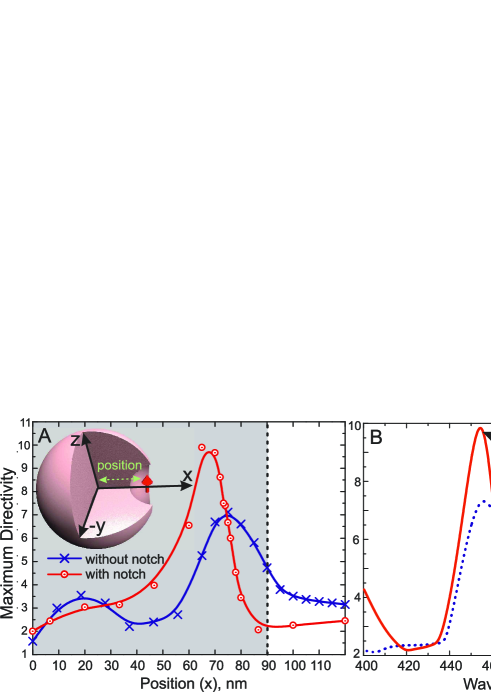
First, we consider a particle without a notch but excited inhomogeneously by a point emitter. To study the problem numerically, we employed the simulation software CST Microwave Studio. Image (Fig. 2A) shows the dependence of the maximum directivity on the position of the source in the case of a sphere nm without a notch, at the wavelength nm (blue curve with crosses). This dependence has the maximum () when the emitter is placed inside the particle at the distance 20 nm from its surface. The analysis shows that in this case the electric field distribution inside a particle corresponds to the noticeable excitation of higher-order multipole modes not achievable with the homogeneous excitation.
Furthermore, the amplitudes of high-order multipoles are significantly enhanced via making a small notch around the emitter (see supplementary ). As it is shown in (Fig. 1), this geometry transforms it into a resonator for high-order multipole moments. In this example the center of the notch is on the nanosphere’s surface. The optimal radius of the notch (for maximal directivity) is equal nm. In (Fig. 2A) the extrapolation red curve with circles, corresponding to simulation results, shows the maximal directivity versus the location of the emitter at the wavelength 455 nm. The maximal directivity is achieved at this wavelength as one can see from (Fig. 2B) that shows the directivity versus with and without a notch. The inset shows the three-dimensional radiation pattern of the structure at 455 nm. This pattern has an angular width (at the level of 3 dB) of the main lobe equal to . This value of directivity corresponds to the normalized effective aperture .
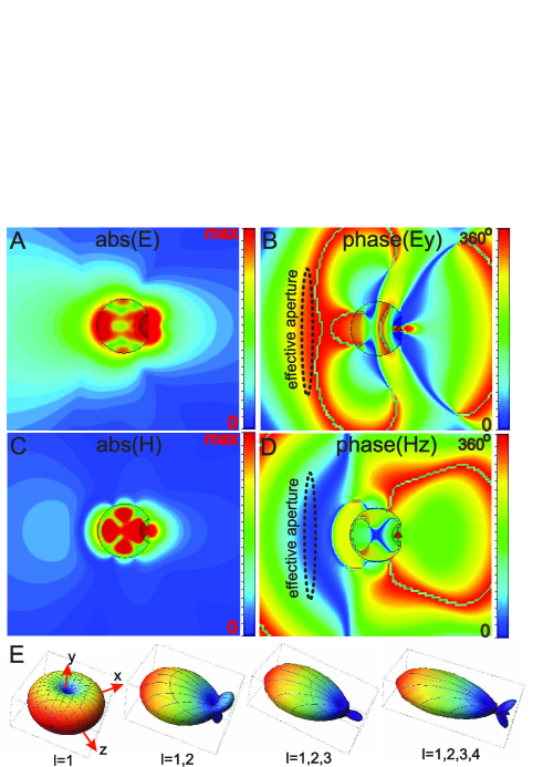
Figures (Fig. 3A,B) show the distribution of the absolute values and phases of the internal electric field and this field in the vicinity of the nanoantenna. Electric field inside the particle is strongly inhomogeneous at 455 nm i.e. in the regime of the maximal directivity (the same holds for the magnetic field, as shown in Fig. 3C,D). In this regime, the internal area where the electric field oscillates with approximately the same phase turns out to be maximal. This area is located near the back side of the spherical particle, as can be seen in figure (Fig. 3B,D). In other words, the effective near zone of the nanoantenna in the superdirective regime of is maximal.
Usually, high directivity of plasmonic nanoantennas is achieved by excitation of higher electrical multipole moments in nanoparticles RollyOL ; Kall09 ; Pakizeh12 or for core-shell resonators consisting of a plasmonic material and a hypothetic metamaterial which would demonstrate the extreme material properties in the nanoscale Alu . Although, the values of directivity achieved for such nanoantennas do not allow superdirectivity, these studies stress the importance of higher multipoles for the antenna directivity.
We have performed the transformation of multipole coefficients into an angular distribution of radiation in accordance to (I2) (see supplementary ) by using distribution of the electric and magnetic fields (Fig.3A-D) and determined the relative contribution of each order . (Fig. 3E) shows how the directivity grows versus the spectrum of multipoles with equivalent amplitudes. The right panel of (Fig. 3E) nearly corresponds to the inset in (Fig. 2) that fits to the results shown in (Fig. 3E).
Generally, the superdirectivity effect has been accompanied by a significant increase of the effective near field zone of the antenna compared to that of a point dipole for which the near zone radius is equal . In the optical frequency range this effect is especially important, considering the crucial role of the near fields at the nanoscale.
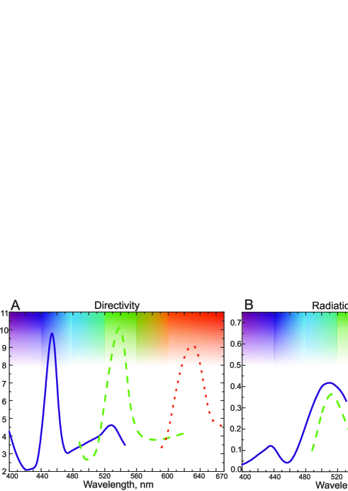
Usually, the superdirectivity regime corresponds to a strong increase of dissipative losses Balanis . Radiation efficiency of the nanoantenna is determined by , where is the power of losses in an nanoantenna. However, the multipole moments excited in our nanoantenna are mainly of magnetic type that leads to a strong increase of the near magnetic field that dominates over the electric one. Since the dielectric material does not dissipate the magnetic energy, the effect of superdirectivity does not lead to a so large increase of losses in our nanoantenna as it would be in the case of dominating electric multipoles. However, since the electric near field is nonzero the losses are not negligible. At wavelengths 440-460 nm (blue light) the directivity achieves 10 but the radiation efficiency is less than 0.1 (see [Fig. 4)]. This is because silicon has very high losses in this range Palik . Peak of directivity is shifted to longer wavelengths with increasing the size of the nanoantenna. For the design parameters corresponding to the operation wavelength 630 nm (red light) the calculated value of radiation efficiency is as high as 0.5, with nearly same directivity close to 10. In the infrared range, there are high dielectric permittivity materials with even lower losses. In principle, the proposed superdirectivity effect is not achieved by price of increased losses, and this is an important advantage compared to known superdirective radio-frequency antenna arrays Balanis and compared to their possible optical analogues – arrays of plasmonic nanoantennas.
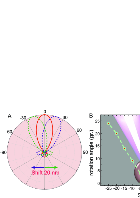
Steering of light at the nanoscale.– Here we examine the response of the nanoantenna to subwavelength displacements of the emitter. Displacement in the plane perpendicular to the axial symmetry of antenna (i.e. along the axis) leads to rotation of the beam without damaging the superdirectivity. Image (Fig.5A) shows the radiation patterns of the antenna with the source in center (solid line) and the rotation of the beam for the 20 nm left/right offset (dashed lines). Shifting of the source right side leads to rotation of pattern to the left, and vice versa. The angle of the beam rotation is equal to 20 degrees, that is essential and available to experimental observations. The result depends on the geometry of the notch. For a hemispherical notch, the dependence of the rotation angle on the displacement is presented in Fig.5B.
Instead of the movement of a single quantum dot one can have in mind the emission of two or more quantum dots located near the edges of the notch. In this case, the dynamics of their spontaneous decay will be well displayed in the angular distribution of the radiation. This can be useful for quantum information processing and for biomedical applications.
Beam steering effect described above is similar to the effect of beam rotation in hyperlens Zhang07 ; Narimanov06 ; LiuReview12 , where the displacement of a point-like source leads to a change of the angular distribution of the radiation power. However, in our case, the nanoantenna has subwavelength dimensions and therefore it can be neither classified as a hyperlens nor as a micro-spherical dielectric nanoscope Kim09 ; Lukyanchuk11 , moreover it is not an analogue of solid immersion micro-lenses Rigneault08 ; Quake10 ; Hanson11 ; Wrachtrup10 , which are characterized by the size 1-5 in the same frequency range. These lens has a subwavelength resolving power due to the large geometric aperture but the value of normalized effective aperture is . Our study demonstrates that the sub-wavelength system, with small compared to the wavelength geometric aperture can have both high directing and resolving power because of a strong increase of the effective aperture compared to the geometrical one.
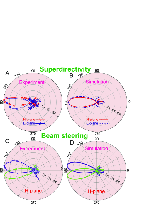
Experimental verification.–We have confirmed both predicted effects studying the similar problem for the microwave range. To do this, we have scaled up the nanoantenna as above to low frequencies. Instead of Si we employ MgO-TiO2 ceramic Krasnok_APL_12 characterized at microwaves by a dispersion-less dielectric constant 16 and dielectric loss factor of 1.1210-4. The results of the experimental investigations (details of which are described in the supplementary materials supplementary ) and numerical simulations of the pattern in both - and -planes are summarized in (Figs. 6A,B). Radiation patterns in both planes are narrow beams with a lobe angle about 35∘. Experimentally obtained coefficients of the directivity in both - and -planes are equal to 5.9 and 8.4, respectively (theoretical predictions for them were equal, respectively, 6.8 and 8.1). Our experimental data are in a good agreement with the numerical results except a small difference for the E plane, that can be explained by the imperfect symmetry of the emitter. Note, that the observed directivity is close to that of an all-dielectric Yagi-Uda antenna with overall size Krasnok_APL_12 . The total size of our experimental antenna is closed to . Thus, our experiment clearly demonstrates the superdirective effect.
Experimental and numerical demonstration of the beam steering effect are presented in (Figs. 6C,D). For the chosen geometry of antenna, displacement of source by 0.5 mm leads to a rotation of the beam about 10∘. Note that the ratio of mm to value of the source displacement 0.5 mm is equal to 37. This proves that the beam steering effect observed at subwavelength displacement of source.
Conclusions. We have suggested a novel approach to achieve superdirectivity of antennas through the excitation of higher-order magnetic multipoles in an optically small dielectric nanoparticle with a noth and a point emitter located inside the notch. For the visible frequency range, we have studied this effect theoretically and demonstrated that a nanoemitter placed in the notch generates efficiently higher-order magnetic miltipole modes responsible for a very high directivity of the nanoantenna not achievable by any other method. We have also suggested an efficient steering effect for an offset of the subwavelength source. We have demonstrated experimentally both superdirectivity and giant beam steering for the microwave frequency range. Combination of superdirectivity with the beam steering and the fact that both the effects can be observed for optical and microwave ranges makes our results very promising for numerous applications in radio physics and nanophotonics.
Acknowledgements. The authors thank B. Lukyanchuk, S. A. Tretyakov and V. V. Klimov for useful discussions and suggestions. The authors thank also E. A. Nenasheva and P. V. Kapitanova for a technical help. This work was supported by the Ministry of Education and Science of the Russian Federation (projects 11.G34.31.0020, 11.519.11.2037, 14.B37.21.0303, 14.132.21.1678, 01201259765), Dynasty Foundation (Russia), and the Australian Research Council.
References
- (1) H. Giessen, M. Lippitz, Science 329, 910, (2010).
- (2) A. G. Curto et al., Science 329, 930, (2010).
- (3) L. Novotny, N. van Hulst, Nat. Photon. 5, 83, (2011).
- (4) P. Biagioni, J.S. Huang, B. Hecht, Rep. Prog. Phys. 75, 024402, (2012).
- (5) A. Alu, N. Engheta, Phys. Rev. Lett. 104, 213902, (2010).
- (6) D. M. Solis, J. M. Taboada, F. Obelleiro, L. Landesa, Optics Express 21, 2369, (2013).
- (7) D. Dregely et al., Nat. Comm. 2, 267, (2011).
- (8) A. E. Krasnok, A. E. Miroshnichenko, P. A. Belov, Yu. S. Kivshar, Optics Exp. 20, 20599, (2012).
- (9) Y. G. Liu et al., Optics Lett. 37, 2112, (2012).
- (10) A. Devilez, B. Stout, N. Bonod, ACS Nano 4, 3390, (2010).
- (11) A. Ludwig, C. D. Sarris, G. V. Eleftheriades, Phys. Rev. Lett. 109, 223901, (2012).
- (12) P. K. Jain, M. A. El-Sayed, Chem. Phys. Lett. 487, 153, (2010).
- (13) S. He, Y. Cui, Y. Ye, P. Zhang, Y. Jin, Materials Today 12, 16, (2009).
- (14) S. R. K. Rodriguez, S. Murai, M. A. Verschuuren, J. Gomez Rivas, Phys. Rev. Lett. 109, 166803, (2012).
- (15) D. S. Filonov et al., Appl. Phys. Lett. 100, 201113, (2012).
- (16) B. Rolly, B. Stout and N. Bonod, OPtics Exp. 20, 20376, (2012).
- (17) A. E. Krasnok, A. E. Miroshnichenko, P. A. Belov, Yu. S. Kivshar, JETP Lett. 94, 635, (2011).
- (18) A. B. Evlyukhin et al., Nano Lett. 12, 3749, (2012).
- (19) A. I. Kuznetsov, A. E. Miroshnichenko, Y. H. Fu, J. Zhang, B. Lukyanchuk, Sci. Rep. 2, 492, (2012).
- (20) Y. H. Fu, A. I. Kuznetsov,A. E. Miroshnichenko, Y. F. Yu, B. Lukyanchuk, Nat. Comm. 4, 1527, (2013).
- (21) C. Balanis, Antenna theory: analysis, design, (New York; Brisbane: J. Wiley, 1982).
- (22) R. C. Hansen, Electrically Small, Superdirective, and Superconducting Antennas, (Wiley-Interscience, 2006).
- (23) R. C. Hansen, R. E. Collin, Small Antenna Handbook, (John Wiley and Sons Ltd, 2011).
- (24) E. Palik, Handbook of Optical Constant of Solids, (San Diego, Academic, 1985).
- (25) S.V. Boriskina, T.M. Benson, P. Sewell, A.I. Nosich, IEEE J. Select. Topics Quantum Electron. 12, 1175, (2006).
- (26) Q. J. Wang et al., PNAS 107, 22407, (2010).
- (27) M. O. Scully, PNAS 107, 22367, (2010).
- (28) Ju Y. Leeet al., Nature 460, 498, (2009).
- (29) Zengbo Wanget al., Nat. Comm. 2, 218, (2011).
- (30) L. H. Gabrielli, M. Lipson, Opt. Expr. 19, 20122, (2011).
- (31) H. Chew, J. Chern. Phys. 87, 1355, (1987).
- (32) V. V. Klimov, M. Ducloy, V. S. Letokhov, J. Mod. Optics 43, 549, (1996).
- (33) A. D. Falco, S. C. Kehr, U. Leonhardt, Opt. Expr. 19, 5156, (2011).
- (34) D. Gerard et al., Opt. Expr. 16, 15297, (2008).
- (35) J. J. Schwartz, S. Stavrakis, S. R. Quake, Science 5, 127, (2010).
- (36) L. Robledo et al., Nature 477, 574, (2011).
- (37) P. Siyushev et al., Appl. Phys. Lett 97, 241902, (2010).
- (38) B. Rolly et al., Opt. Lett. 36, 3368, (2011).
- (39) T. Pakizeh, M. Kall, Nano Lett. 9, 2343, (2009).
- (40) S. H. Alavi Lavasani, T. Pakizeh, Opt. Lett. 29, 1361, (2012).
- (41) A. Alu, N. Engheta, IEEE Trans.Ant.Prop. 55, 3027, (2007).
- (42) See supplementary materials on Nature Physics Online.
- (43) Z. Liu, H. Lee, Y. Xiong, X. Zhang, Science 315, 1686, (2007).
- (44) Z. Jacob, L. V. Alekseyev, E. Narimanov, Opt. Expr. 14, 8247, (2006).
- (45) Dylan Lu, Zhaowei Liu, Nat. Comm. 3, 1205, (2012).
I Supplementary Material
Multipole expansion for superdirectivity. In this section, we demonstrate how to find multipole modes excited in the all-dielectric superdirective nanoantenna which are responsible for its enhanced directivity. We expand the exactly simulated internal field, producing the polarization currents in the nanoparticle, into multipole moments following to Jackson1 . The expansion is a series of spherical harmonics with the coefficients and , which characterize the electrical and magnetic multipole moments Jackson1 :
| (I1) |
where and are densities of the induced electrical charges and polarization currents that can be easily expressed through the internal electric E and magnetic H fields of the sphere, - spherical harmonics of the orders , , - spherical Bessel function order and is the speed of light. Coefficients and determine the electric and magnetic mutipole moments, namely dipole at , quadrupole at , octupole at etc..
The multipole coefficients determine not only the mode structure of the internal field but also the angular distribution of the radiation. In particular, in the far field zone electric and magnetic fields of multipole order depend on the distance as and expression for the angular distribution of the radiation power can be written as follows:
| (I2) |
Here is the solid angle element in spherical coordinates and - unit vector of the observation point. All coefficients and give the same contribution to the radiation, if they have the same values. Since higher-order multipoles for optically small systems have usually negligibly small amplitudes compared to and , they are, as a rule, not considered.
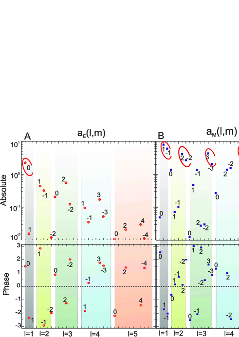
The amplitudes of multipole moments for electric and magnetic fields distribution (Fig.3A-D) are shown in figure (S. I1), where we observe strong excitation of , , , , , , , , , and . These multipole moments determine the angular pattern of the antenna. All other ones give a negligible contribution. Absolute values of all magnetic moments are larger than those of the electric moments in the corresponding multipole orders, and the effective spectrum of magnetic multipoles is also broader than that of the electric moments. Thus, the operation of the antenna is mainly determined by the magnetic multipole response. Absolute values of multipole coefficients of the same order are practically equivalent, however, the phase of some coefficients are different. Therefore, the modes with and form a strong anisotropy of the forward–backward directions that results in the unidirectional radiation.
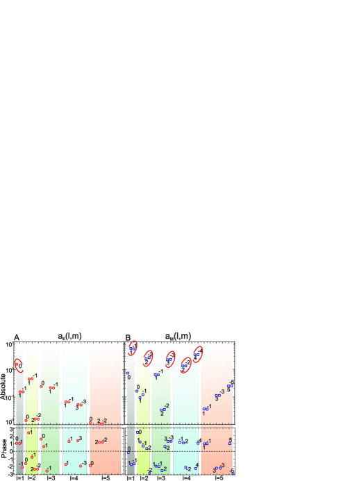
Multipole expansion for beam steering. To interpret beam steering effect, consider the result of field expansion to magnetic multipoles, as shown in (S.I2). In the case of asymmetrical location (the 20 nm left offset) of the source in the notch absolute values of are different. This means that the mode is excited more strongly than , or vice versa, that depends on direction of displacement. The effect of superdirectivity remains at offset of source until to the edge of notch. Small displacements of the source along and do not lead to the rotation of the pattern.
Details and technique of experiment
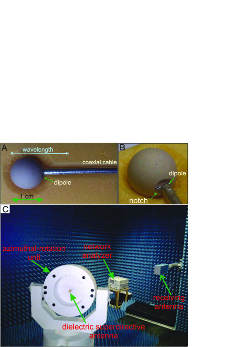
This topic provides some details and technique of the experiments. For confirmed superdirectivity and beam steering effects, we have scaled up the nanoantenna as above to low frequencies. Instead of Si we employ MgO-TiO2 ceramic KrasnokAPL characterized at microwaves by a dispersion-less dielectric constant 16 and dielectric loss factor of 1.1210-4. We have used the sphere of radius mm and applied a small wire dipole Bal excited by a coaxial cable [see (S. I3A,B)]. The common-mode radiation (i.e. that of the cable) was prevented with a mini-balun located inside the sphere. The size of the hemispherical notch is approximately equal to mm. Styrofoam material with the dielectric permittivity close to 1 is used to fix the antenna in the azimuthal-rotation unit, as shown in (S. I3C). First, we have performed a full-wave simulations of the whole structure antenna (with the CST Microwave Studio), and observed the superdirectivity at the frequency 16.8 GHz. Next, we have studied experimentally the radiation pattern of this antenna in the anechoic chamber. Radiating power was measured by ultra-wideband antenna TMA (1.0-18.0 HF) which was located in the far field radiation zone. The results of the experimental investigations and numerical simulations of the pattern in both - and -planes are summarized in (Figs. 6A,B) [see main part]. Radiation patterns in both planes are narrow beams with a lobe angle about 35∘. Experimentally obtained coefficients of the directivity in both - and -planes are equal to 5.9 and 8.4, respectively (theoretical predictions for them were equal, respectively, 6.8 and 8.1). Our experimental data are in a good agreement with the numerical results except a small difference for the E plane, that can be explained by the imperfect symmetry of the wire dipole.
Experimental and numerical demonstration of the beam steering effect at microwave are presented in (Figs. 6C,D) [see main part]. For the chosen geometry of antenna, displacement of source by 0.5 mm leads to a rotation of the beam about 10∘. Note that the ratio of mm to value of the source displacement 0.5 mm is equal to 37. This proves that the beam steering effect observed at subwavelength displacement of source.
References
- (1) J. Jackson, Classical Electrodynamics (New York : Wiley, 1998).
- (2) D. S. Filonov et al., Appl. Phys. Lett. 100, 201113, (2012).
- (3) C. Balanis, Antenna theory: analysis, design, (New York; Brisbane: J. Wiley, 1982).