Dielectric Coatings for IACT Mirrors
Abstract
Imaging Atmospheric Cherenkov Telescopes for very-high energy gamma-ray astronomy need mirror with high reflectance roughly in the wavelength between 300 and 550 nm. The current standard reflective layer of such mirrors is aluminum. Being permanently exposed to the environment they show a constant degradation over the years. New and improved dielectric coatings have been developed to enhance their resistance to environmental impact and to extend their possible lifetime. In addition, these customized coatings have an increased reflectance of over 95% and are designed to significantly lower the night-sky background contribution. The development of such coatings for mirrors with areas up to 2 m2 and low application temperatures to suite the composite materials used for the new mirror susbtrates of the Cherenkov Telescope Array (CTA) and the results of extensive durability tests are presented.
1 Introduction
Imaging Atmospheric Cherenkov Telescopes (IACTs) for very-high energy (VHE) gamma-ray astronomy image the Cherenkov light of particle showers in the atmosphere onto a photosensitive detector. The wavelength range of interest is roughly between 300 and 550 nm. Typically, IACTs have tesselated mirror areas of the order of 1 m2 and larger. The current standard (e.g. in H.E.S.S., VERITAS and partially MAGIC) is mirrors with glass surfaces, coated on the front surface with aluminium (Al) which is protected by a single protective layer (e.g. SiO2, Al2O3). Not being protected by a dome, the mirrors are constantly exposed to the environment and show a loss of reflectance of a few per cent per year. This requires re-coating of all mirrors after a few years of operation. For the future CTA observatory (see [1]) with a total planned mirror area of about 10,000 m2 this would mean a significant maintenance effort. Coatings which increase the lifetime of the mirrors can therefore play a major role in keeping the maintenance costs of the observatory low. In addition, coatings with higher reflectance in the relevant wavelength range compared to the classical Al + SiO2 coatings will increase the sensitivity of the instrument while a reduced reflectance above roughly 550 nm can help to suppress sensitivity to background light from the night sky.
2 Coatings under Investigation
Aluminium coatings with a single SiO2 layer typically show a reflectance of 80 to 90% between 300 and 550 nm. To improve the reflectance and the durability of the mirrors two commercially available coating options are currently under investigation in this study (further coating designs are being investigated at the University of Tübingen and are presented in [2].).
(a) A three-layer protective coating (SiO2 + HfO2 + SiO2) on top of an Al coating. This already enhances the reflectance by about 5%. Fig. 1 shows the reflectance of this coating in comparison to the reflectance of an Al + SiO2 coating.
(b) A dielectric coating, consisting of a stack of many alternating layers of two materials with different refractive indices, without any metallic layer. Properly optimized, this results into an pure interference mirror that allows a box-shaped reflectance curve to be custom-made with reflectance in a defined wavelength range and elsewhere. The first attempts were designed such that a range of 300 to 600 nm was covered. This is called “version 1” in the following. For “version 2” the design was adjusted such that a cut-off around 550 nm allows the reduction of the the night-sky background contribution (first emission line around 556 nm). The latter might become important in combination with a possible future replacement of the current photomultiplier tubes in the photodetectors of the telescopes (which are not particularly susceptible to night-sky background) by silicon detectors that have a good quantum efficiency for wavelengths above 550 nm. The reflectance curves of these coatings are as well shown in Fig. 1.
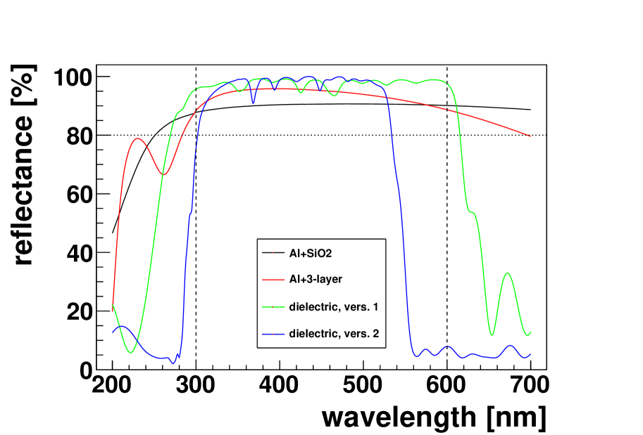
Most durability testing reported on in the following has been performed on version 1 and is currently ongoing for version 2. Nevertheless, the materials and the technology used are exactly the same for both versions, the only difference is the number of layers.
3 Application to Large Substrates and at Low Temperatures
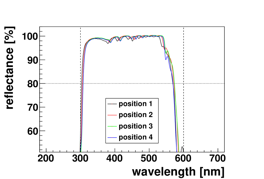
The largest mirrors needed for CTA will be of hexagonal shape with 1.5 m distance from flat to flat, resulting in a mirror area of roughly 2 m2. While the Al based coatings are in principle commercially available for substrates of this size, applying the dielectric coatings to such large surfaces was more challenging and needed additional development effort. Given that these are interference coatings consisting of many layers of materials with different refractive indices a homogeneuos thickness of each layer over the full mirror size is important. Fig. 2 shows the uniformity achieved in the reflectance over the diameter of such a big mirror.
The second challenge was created by the mirror substrates themselves. Many substrate technologies under development for CTA are sandwich structures of different materials that are glued together [3, 4, 5]. Most of these glues cannot be heated to temperatures above 80∘ C without damage. While Al-based coatings can be applied without heating the substrate and with only limited heat impact from the evaporation sources during the coating process, a special process was developed for the dielectric coating to keep the substrate temperature below the required limit. This comes at the expense of longer coating times and therefore higher costs. In parallel, the option is being investigated to coat only the front glass sheet and then to construct the sandwich with this coated sheet rather than coating the final mirror. This way the the more costly low-temperature process would not be needed.
4 Durability Testing
A series of durability tests have been performed in the laboratory
with small glass samples coated with the different coatings
to evaluate their resistance to environmental impact.
Temperature and humidity cycling: Samples of the three-layer coating as well as of version 1 of the dielectric coating have been exposed to overlapping cycles in temperature (-10∘ C T 60∘ C; 5 h cycle duration) and in humidity (5% to 95%; 8h cycle duration) for a total of approximately 8000 h. The different cycle duration was chosen to expose the samples to all possible combinations of temperature and humidity. The reflectance as a function of wavelength of the samples has been measured with a spectrophotometer (angle of incidence 7∘) before and after the cycling. The results of these measurements are shown in Fig. 3.
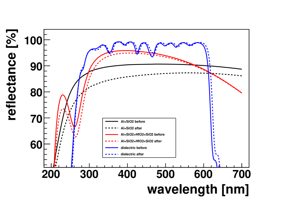
The classical Al + SiO2 coating shows a significant loss of reflectance.
The Al coating with the three layer protective coating exhibts a much
smaller change in reflectance after the cycling and the dielectric
coating has not changed its reflective properties at all within
the accuracy of the measurement. Samples of version 2 of the
dielectric coating optimized for the cutoff at 550 nm are currently
undergoing the same test.
Adhesion tests: Coating adhesion was tested by applying a clear tape
with an adhesion power of 16 N per 25 mm to
the coated surface of the samples and removing it at a rate of s per
25 mm (so-called “snap test”). All tested samples survived this procedure
without any removal of coating, including the new coatings under
investigation and the classical Al+SiO2 coating.
Abrasion tests: Three different abrasion tests have been performed on samples with all three coatings:
a) A standard cheesecloth test using a force of
10 N and 50 strokes on the coated surface was performed.
The Al+SiO2 reference samples showed mild to moderate abrasion
under this test (defined as few to many visible scratches
left behind after the test), the three-layer coating showed
very mild to mild abrasion (one or two to few scratches) and the
dielectric coating none to very mild abrasion (zero to one or two scratches).
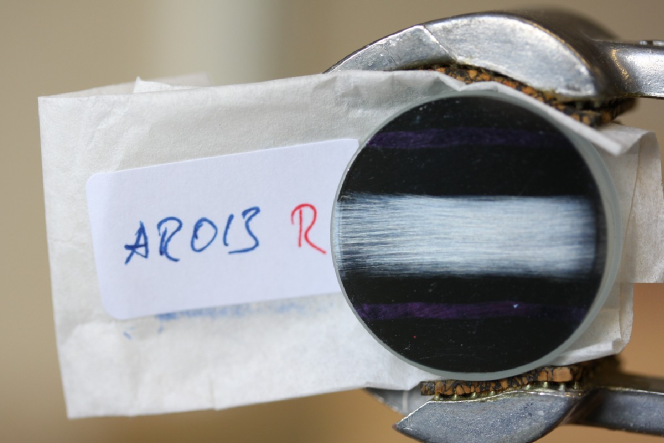
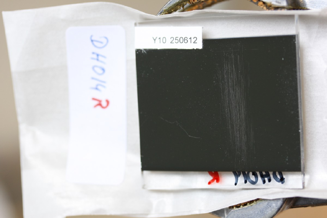
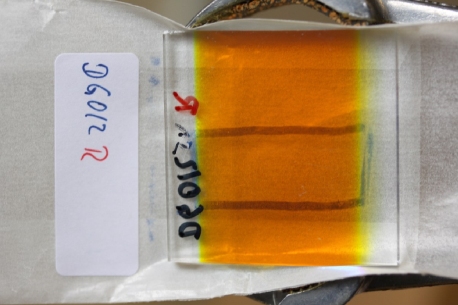
b) In a more severe test an eraser was used to perform 20 strokes with a force of 10 N. After this test all three coatings showed signs of abrasion, but again to very different levels: the reference samples coated with SiO2 showed serious to severe abrasion (removal of some to most of the coating), the three-layer coating moderate to severe abrasion (many scratches to removal of some coating), and the dielectric coating only showed very mild to mild abrasion (one or two to few scratches). Figure 4 shows a few samples after this severe abrasion test.
c) Samples with all three coatings were exposed to a sand-blasting test. The abrading medium used was silicon carbide with a grade of 220 m. The flow rate was approximately 25 g/min and the total amount of abrading medium used per sample was 125 g. The setup was operated using an air pressure of 15 kPa and the air was fed in at a rate of 50 l/min. The sample was placed under an angle of 45∘ under the abrasive jet nozzle. This test results into an ellipse on the coated surface on which the coating is partially and/or fully removed. The sizes of these ellipses are a measure of how easily the coating is abraded. Figure 5 shows three samples after the sand-blasting test; at the top the Al + SiO2 coating, in the middle the Al + SiO2 + HfO2 + SiO2 coating and at the bottom the dielectric coating.
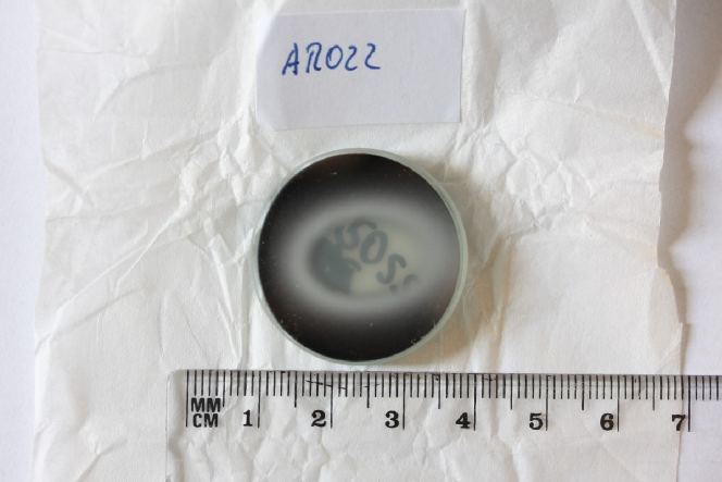
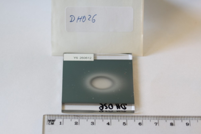
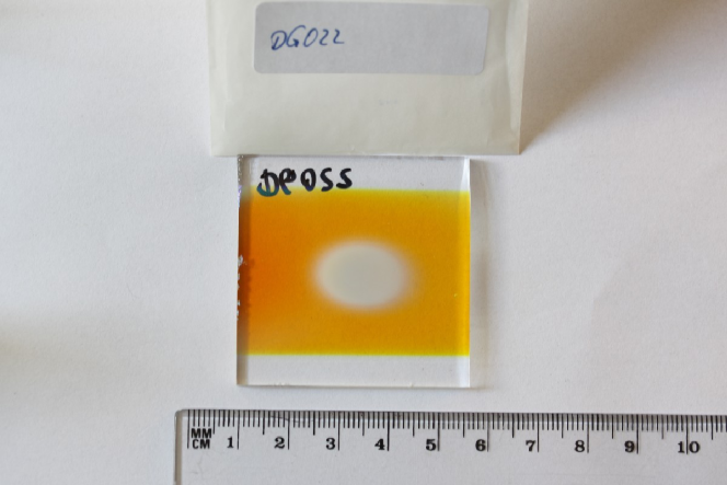
Three elliptical areas have been measured to quantify the different abrasion levels of the three coatings: The “clear area”, meaning the central region in which the coating has been fully removed, the darker “partially clear area” around it and the penumbra being the reach of the silicon carbide, which shows as a light ‘halo’. The results are given in Tab. 1 and demonstrate that the abrasion resistance of the dielectric coating is significantly higher than of the Al-based coatings.
| Coating | Clear Area | Partially Clear | Penumbra |
|---|---|---|---|
| Al+SiO2 | |||
| 3-layer | |||
| dielectric |
Artificial Bird Faeces: Samples of all coatings have been treated with
pancreatin, a pancreas enzyme that is regularly used to simulate the effects
of bird feaces on lacquers and other material. A 1:2 mixture of pancreatin
and de-ionized water was applied to the coated surfaces of the samples
and they were “baked” for 4 weeks at 40∘ C in a climate
chamber to simulate the effect of the bird faeces staying on the mirror
surface for some time in a hot and dry environment as is typical
for locations of Cherenkov telescopes. No influence on either
of the the three coatings was observed after cleaning the samples and
repeated reflectance measurements.
5 Conclusions and Outlook
In the laboratory tests described above, the three layer protective coating on top of an aluminium coating performs slightly better than the standard Al + SiO2 coating. The dielectric coating shows a significantly better performance still. Nevertheless, the predictive power of these laboratory tests for the real outdoor performance is not clearly established and additional outdoor experience is needed. Over the last 2 years all of the approximately 1520 mirrors of the 4 original telescopes of the H.E.S.S. experiment in Namibia have been exchanged and refurbished. 380 mirrors have the standard Al + SiO2 coating, rougly 1040 the Al + three layer coating, and about 100 mirrors the dielectric coating. This way data on long-term outdoor exposure will become available.
One problem of the three layer protective coating directly applied on top of the Al layer has been noted for these mirrors: it was observed that in the first months after coating the interference minimum around 280 nm (see Figs. 1 and 3) was getting deeper, slightly affecting the reflectance at 300 nm as well. To solve this problem, an additional protection layer inbetween the Al and the three-layer coating is now being applied to prevent this effect. Detailed tests of this improved coating are ongoing.
A significant problem of the dielectric coating has been detected in a study that intended to compare different substrate technologies in terms of the probability to form condensation on the reflective surface [6]. It was observed that the same substrates are more likely to mist over if coated with the dielectric coating rather than with an Al based coating. Laboratory tests have associated this effect with a much higher emissivity of the dielectric coatings in the infrared (8-14 m). Investigations are ongoing to solve this problem by applying an additional layer below the dielectric coating that does not reflect in the regime of the night-sky background but has a high reflectance in the mid- infrared.
To conclude, the Al + SiO2 + HfO2 + SiO2 as well as the dielectric coating are now readily available alternatives to the standard Al + SiO2 coating. The three layer coating provides an about 5% better reflectance and a slightly better performance in durability tests in the laboratory at no significant extra cost. The dielectric coating can now be applied up to substrate areas of 2 m2 and at substrate temperatures C during the coating process. This covers the largest mirrors forseen for CTA and is suitable for the application on glued sandwich substrates. It provides a significantly better reflectance in the desired wavelength range, a significant suppression of the night-sky background and a significantly better performances in the durability tests, but it needs further improvement concerning the high emissivity in the infrared that leads to a higher probability of forming condensation on the mirrors.
Acknowledgements
We gratefully acknowledge support from the agencies and organisations listed in this page: http://www.cta-observatory.org/?q=node/22.
References
- [1] W. Hofmann et al., arXiv:1008.3702 (2010)
- [2] A. Bonardi et al., these proceedings (2013) contribution 0207
- [3] R. Canestrari et al., Optical Engimeering 52 (2013) 051204
- [4] P. Brun et al., NIM A 714 (2013) 58
- [5] A. Förster et al., these proceedings (2013) contribution 0747
- [6] P. Chadwick et al., these proceedings (2013) contribution 0847