Single-mode subwavelength waveguides with wire metamaterials
Abstract
We study the eigenmodes of a slab of a wire metamaterial and demonstrate that such a waveguiding structure supports deep-subwavelength propagating modes exhibiting properties of a single-mode waveguide at any fixed frequency below the plasma frequency of metal wires. We compare our analytical results with the dispersion relations extracted from the experimental measurements.
Guided electromagnetic waves are a special type of localized modes which exist either at interfaces of dissimilar media (surface modes) or are trapped by the regions of high-dielectric material (waveguide modes). Guided modes can propagate in various types of waveguides such as dielectric slab waveguides, photonic fibers, and metallic slot waveguides WaveguideBook . Here we study a novel type of waveguide created by a slab of wire metamaterial wirereview of a finite thickness, and exhibiting a number of peculiar features not found in conventional waveguides.
Wire metamaterials have a number of unique properties wirereview , including the possibility of the subwavelength image transfer Subwavelength1 ; Subwavelength2 ; Subwavelength3 . Localized modes in such structures have been studied theoretically Belovmodes ; Theor , and it was shown that these modes are similar to the so-called spoof plasmons, a special class of surface modes which propagate along corrugated metal or semiconductor surfaces spoof001 ; spoof01 ; spoof . It was also shown that these guided modes can be useful for far-field superlensing Finkfirst ; FinkPRL and deep-subwavelength waveguiding Finkwaveguides of electromagnetic waves. However, despite of their peculiar properties, the studies of guided modes and their possible applications were mainly theoretical with no experimental verification of their actual propagation in wire metamaterials.
In this Letter, we discuss several unique properties of this novel type of guided modes, compare them with the corresponding modes of conventional dielectric waveguides, and also present the first direct experimental measurements of the guided modes propagation in a slab of wire metamaterial.
We study the waveguiding wire-metamaterial structure shown in Fig. 1(a) where guided modes propagate in the direction. We describe a slab of wire metamaterial within a local effective theory approach. This approximation is valid when the wire-lattice period is much less than the wavelength. Within this approximation, the wire metamaterial can be characterized by a diagonal tensor of dielectric permittivity with one component parallel to the wires being equal to infinity, and two other components being equal to the dielectric permittivity of the host medium wirereview . Next, we derive the dispersion relations for the waveguide modes of a slab waveguide made of this extremely anisotropic medium (see Fig. 1(b)).
To obtain analytical expressions for waveguide modes, we consider TM-polarization of light. We then recall that in the case of extremely anisotropic metamaterial it support propagation only of TEM-polarized waves with magnetic field given by , where is the wavevector in vacuum. We then apply the continuity boundary conditions for the tangential magnetic and electric fields. Equating the determinant of the obtained linear system to zero, we find the dispersion equation for the localized modes (see also Ref. FinkWCM ),
| (3) |
where . When the dielectric host medium is absent (), Eqs. (3) become equivalent to the dispersion relations obtained earlier in Ref. Finkfirst .
Figure 2(a) presents the dispersion curves of the guided modes in a slab of wire metamaterial. For comparison, we show also the dispersion curves of the guided modes in a slab of conventional dielectric material of the same thickness with the refractive index 2.0 [see red and green curves in Fig. 2(a)]. We observe some similarities between the dispersions of dielectric and metamaterial waveguides. In particularly, both the structures have only one fundamental eigenmode with no cut-off. Higher-order modes are defined by the cut-off frequencies: , for the metamaterial waveguide, and , for the dielectric waveguide, where is the index of the corresponding eigenmode. At the same time, we observe sufficient differences between the modes of dielectric and metamaterial waveguides. First, the waveguide number of the dielectric waveguide is always limited with the refractive index of the waveguide core: , thus dispersion curves of all the guided modes lie in the blue area shown in Fig. 2(a). The waveguide number of the eigenmodes in the metamaterial waveguide generally is not bounded if we do not account for losses and internal periodicity of the metamaterial, and they can extend to infinity, as in the case of surface plasmon polaritons. Moreover, only one eigenmode can exist in the metamaterial waveguide at the fixed frequency, whereas in the case of dielectric waveguide, arbitrary large number of modes may exist at the fixed frequency for sufficiently large frequencies. Therefore, the metamaterial slab is a single-mode waveguide for arbitrary frequency (providing that the frequency is below the plasma frequency of the metal). While the studied eigenmodes exhibit both the properties of guided modes and surface waves, we call them the waveguide modes, because their dispersion depends on the thickness of the metamaterial slab, and the electric field is localized in the bulk rather than at the surface.
Figure 2(b) shows the dispersion curves of the fundamental guided mode of the metamaterial slab depending on the refractive index of the host media. We notice that the guided mode exists even for the case when the refractive index is less than unity, which is not the case for dielectric waveguides, where no guided modes are possible for a low-index core. We should also mention that for the metamaterial eigenmodes the energy is transferred only outside the slab, and no energy transfer is present inside the slab, as shown in Fig. 2(c).
Next, we study the waveguide modes experimentally for the microwave frequency range, using a sample made of a wired metamaterial shown in Fig. 1. A two-dimensional array of metallic wires of length cm and period of cm is placed in a dielectric host media. The slab dimensions are cm. We excite the waveguiding metamaterial structure with a point source, positioned at the distance of mm from the structure surface. The signal is then collected with a probe at the opposite side of the structure. Scanning the backside of the structure with the receiver allows to build the amplitude and phase maps of the transmitted radiation.
Figure 3 shows our experimental and numerical results for the transmitted radiation at the frequency MHz, for the case when the source is shifted along the horizontal axis towards the left edge of the structure. In the numerical modeling, we observe the formation of the standing mode formed by the surface waves, as predicted earlier Finkfirst . In our experiment, the amplitude and phase patterns are significantly blurred, and the presence of the standing wave is hardly distinguishable. This effect could be both due to the presence of losses in the dielectric host media and due to that all the wires are of slightly different lengths, which is crucial for the formation of standing wave. Moreover, sensitivity of the experimental measurements is limited significantly by the dynamical range of the setup. In particular, at least dB have been lost due to the source and probe mismatch.
Figure 4 shows the amplitude and phase maps of the transmitted radiation for three different values of frequencies. We can observe a rapid phase change for the case of MHz. Furthermore, the amplitude map of the radiation at this frequency is characterized by a sharp dip at certain distance from the source. It is evident that for smaller and larger distances ( MHz and Mhz), none of these distinctive features is observed.
Next, we extract the waveguide numbers of the transmitted radiation from the phase maps. Assuming that the most part of the electromagnetic radiation is transferred in the guided modes, we assume the spatial dependence of the field in the transmitted wave to be , where is the distance from the source in the plane parallel to the structure surface, and is the wavenumber. Thus, the phase of the transmitted radiation should be linearly proportional to the wavenumber . Therefore, it is possible to extract the dispersion of from the phase distribution map measured at different frequencies. Figure 5 shows the extracted values of the wavenumber together with the fitting with Eq. (3). We observe that the experimentally obtained dispersion relations agree well with the theoretical results. In the fitting, we have used the dielectric host media refractive index as a fitting parameter, since it was now known a priori. The resulting value of is close to the typical values of the refractive index of the acetal for the considered frequency range.
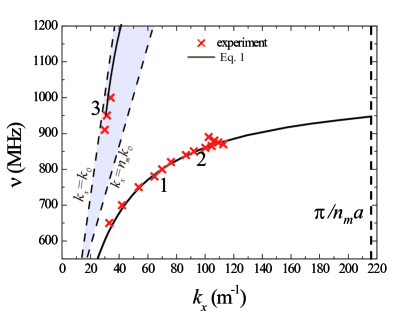
We note that the result (3) for the effective dispersion does not take into account the inherent periodicity of the metamaterial structure which limits the range of the allowed wavenumbers by the edge of the Brillouin zone , where is the lattice spacing. However, the measured wavenumbers do not reach this limiting value in experiment, and the dispersion curve bends in the middle of the band close to the value . This bending of the dispersion curves is typical for surface plasmon polaritons in the presence of losses. The observed bending of the dispersion curves in our case originates from the losses in the dielectric host media and radiation losses in the structure.
In conclusion, we have studied the properties of waveguiding modes propagating in the slab of wire metamaterial taking into account dielectric permittivity of the host medium, and compared them with the corresponding properties of conventional waveguides. We have studied experimentally propagating guided modes in a slab of wire metamaterial and measured their dispersion.
This work was supported by the Ministry of Education and Science of Russian Federation (Grants No. 11.G34.31.0020, 14.B37.21.1649 and 14.B37.21.1941), the Dynasty Foundation, Russian Foundation for Basic Research (RFBR), and the Australian Research Council.
References
- (1) A. Yariv, Optical Electronics (Oxford University Press, 1990).
- (2) C.R. Simovsky, P.A. Belov, A.V. Atrashenko, and Yu. S. Kivshar, Adv. Mat. 24, 4229 (2012).
- (3) M.G. Silveirinha, P.A. Belov, and C.R. Simovski, Phys. Rev. B 75, 035108 (2007).
- (4) P.A. Belov, Y. Zhao, S. Tse, P. Ikonen, M.G. Silveirinha, C.R. Simovski, S.A. Tretyakov, Y. Hao, and C. Parini, Phys.Rev. B 77, 193108 (2008).
- (5) P.A. Belov, G.K. Palikaras, Y.Zhao, A.Rahman, C.R. Simovski, Y.Hao, and C. Parini, Appl. Phys. Lett. 97, 191905 (2010).
- (6) Y. Zhao, G. Palikaras, P.A. Belov, R.F Dubrovka, C.R. Simovski, Y. Hao, and C.G. Parini, New J. Phys. 12, 103045 (2010).
- (7) P.A. Belov and M.G. Silveirinha, Phys. Rev. E 73, 056607 (2006).
- (8) S.A. Maier, S.R. Andrews, L. Martin-Moreno, and F. J. Garcia-Vidal, Phys. Rev. Lett. 97, 176805 (2006).
- (9) M. Navarro-Cia, M. Beruete, S. Agrafiotis, F. Falcone, M. Sorolla, and S.A. Maier, Opt. Exp. 17, 18184 (2009).
- (10) E.K. Stone and E. Hendry, Phys. Rev. B 84, 035418 (2011).
- (11) F. Lemoult, M. Fink, and G. Lerosey, Nature Commun. 3, 889 (2012).
- (12) F. Lemoult, G. Lerosey, J. Rosny, and M. Fink, Phys. Rev. Lett. 104, 203901 (2010).
- (13) F. Lemoult, N. Kaina, M. Fink, and G. Lerosey, Nature Phys. 9, 55 (2013).
- (14) F. Lemoult, M. Fink, and G. Lerosey, Waves in Random and Complex Media 21, 591 (2011).