Electron Cloud Buildup Characterization Using Shielded Pickup Measurements and Custom Modeling Code at CESRTA
Abstract
The Cornell Electron Storage Ring Test Accelerator experimental program includes investigations into electron cloud buildup, applying various mitigation techniques in custom vacuum chambers. Among these are two 1.1-m-long sections located symmetrically in the east and west arc regions. These chambers are equipped with pickup detectors shielded against the direct beam-induced signal. They detect cloud electrons migrating through an 18-mm-diameter pattern of small holes in the top of the chamber. A digitizing oscilloscope is used to record the signals, providing time-resolved information on cloud development. Carbon-coated, TiN-coated and uncoated aluminum chambers have been tested. Electron and positron beams of 2.1, 4.0 and 5.3 GeV with a variety of bunch populations and spacings in steps of 4 and 14 ns have been used. Here we report on results from the ECLOUD modeling code which highlight the sensitivity of these measurements to the physical phenomena determining cloud buildup such as the photoelectron production azimuthal and energy distributions, and the secondary yield parameters including the true secondary, re-diffused, and elastic yield values.
1 Introduction
The Cornell Electron Storage Ring Test Accelerator (CESRTA) project [1] has been exploiting the versatility of the 768-m-circumference CESR storage ring to obtain measurements of low-emittance beams and electron cloud buildup for electron and positron beams ranging from 1.8 to 5.3 GeV. The program includes the installation of custom vacuum chambers with retarding-field-analyzer (RFA) ports and shielded pickup (SPU) detectors of the type shown in Fig. 1.
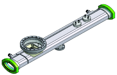
The RFA port is shown on the left end, and two circular SPU modules are shown on the right end of the chamber, each with two ports. In one case the two ports are placed longitudinally, and in the other case the two ports are arranged transversely, providing laterally segmented sensitivity to the cloud electrons. Thus the centers of buttons are 0, and mm from the horizontal center of the chamber. The ports consist of 169 0.76-mm-diameter holes arranged in concentric circles up to a maximum diameter of 18 mm. The top of the vacuum chamber has been machined such that the holes are aligned vertically. The transparency factor for vertical trajectories is 27%. The approximate 3:1 depth-to-diameter factor is chosen to effectively shield the detectors from the signal induced directly by the beam, as shown in Fig. 2.
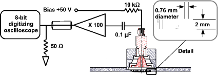
Time-resolved measurements provide time structure information on electron cloud (EC) development, in contrast to the time-integrated RFA measurements [2]. However, they have relatively primitive energy selection, since they have no retarding grid. Also, the position segmentation is more coarse, the charge-collecting electrodes being of diameter 18 mm. Data has been recorded with biases of 0 and V relative to the vacuum chamber. The studies described here address exclusively the data with bias V in order to avoid contributions to the signal from secondary electrons escaping the pickup. Such secondaries generally carry kinetic energy insufficient to escape a 50 V bias. This choice of bias obviously provides sensitivity to cloud electrons which enter the port holes with low kinetic energy. The front-end readout electronics comprise two Mini-Circuits ZFL-500 broadband amplifiers with input impedance for a total gain of 40 dB. Digitized oscilloscope traces are recorded with 0.1 ns step size to 8-bit accuracy with auto-scaling, averaging over 8k triggers.
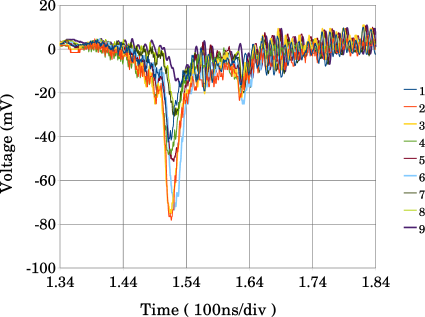
Figures 3 and 4 show examples of digitized SPU signals produced by two positron bunches spaced 28 ns apart. Anticipating the following discussion of the interpretation of these signals, we note that
the time characteristics of these signals carry much detailed information on EC development. The leading bunch seeds the cloud and produces photoelectrons which drift into the SPU detector. The leading signal is produced by the photoelectrons produced on the bottom of the vacuum chamber, since they are the first to arrive at the top of the chamber, accelerated by the positron bunch directly at the detector. The second signal peak is larger, since it carries a contribution from the cloud present below the beam at the time of arrival of the second bunch. Since these cloud electrons have been produced by wall interactions during the preceding 28 ns, the size and shape of this second signal peak depends directly on the secondary yield characteristics of the vacuum chamber surface. The variety of signal shapes and magnitudes for the two-bunch measurements shown in Figs. 3 and 4 make clear that detailed information on all aspects of EC buildup in different mitigation environments can be obtained. Below we describe the numerical modeling which instructs our interpretation of these measurements.
2 Numerical Modeling of EC Buildup
The EC buildup modeling code ECLOUD [3] has been under active development for the purposes of CESRTA since 2008. Developed at CERN in the 1990s, it has seen widespread application for EC phenomena observed at the CERN LHC, SPS, and PS, as well as at KEK and RHIC. It has been extensively benchmarked [4] against the 2D buildup code POSINST [5] and has successfully described the CESRTA measurements of EC-induced coherent tune shifts [6, 7, 8, 9, 10]. ECLOUD includes simulation algorithms for photoelectron generation, for time-sliced macroparticle tracking in the 2D electrostatic fields sourced by the beam and the cloud, and 3D tracking in a variety of ambient magnetic fields, as well as for a detailed model of the interactions of cloud electrons with the vacuum chamber surface producing secondary electrons. A variety of options have been implemented to model the CESRTA measurements. The azimuthal distribution of photoelectron generation sites for the modeling results presented in this paper are provided by the recently developed photon reflection and tracking modeling code Synrad3D [11], which calculates photon rates and absorption sites throughout the CESR lattice using a detailed model of the vacuum chamber around the entire ring and a given set of vacuum chamber surface roughness parameters. The photoelectron generation portion of the ECLOUD code has been generalized to allow admixtures of various power-law photoelectron energy distributions in addition to the Gaussian functions originally provided. The model for the generation of secondary electrons has been generalized to allow the same set of parameters used in the POSINST code. Response functions for the SPU detector have been implemented. As a function of incident angle and energy, a fraction of a macroparticle charge hitting the wall in the region of the detector on the top of the beam-pipe contributes to the modeled signal. The remaining charge can generate secondary electrons. A contribution to the signal from secondaries generated on the walls of the 0.76-mm-diameter SPU holes is also calculated. The modeled signal in each time slice thus carries a statistical error associated with the number of contributing macroparticles. Typically macroparticles are generated during the passage of each bunch, each macroparticle carrying thousands of electron charges. The development of the cloud is calculated in 100 time slices during the passage of the 1-cm long bunch, and in 2000 time slices between bunch passages.
3 Photoelectron Model
The SPU signal during the first few nanoseconds following passage of a single bunch of positrons is produced primarily by photoelectrons produced on the bottom surface of the vacuum chamber, since it is the surface nearest the detector where the electrostatic force from the beam bunch is directed at the detector. Figure 5
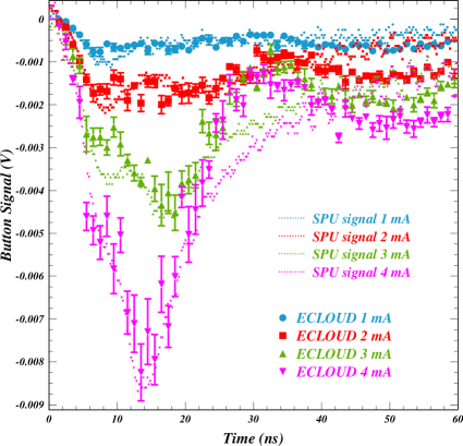
clearly shows such signals increasing in magnitude and arriving earlier as the bunch population is raised from to . The increase in signal arises not only because of the higher rate of synchrotron radiation photons, but also because of the greater beam kick accelerating the lower-energy (and more common) photoelectrons into the detector sooner. Varying the bunch current therefore allows a momentum analysis of photoelectron production. Note for example that the leading edge of the pulse does not come appreciably earlier for higher bunch populations, indicating that the photoelectron energy distribution, rather than the beam kick, governs its arrival time. Indeed, the 5-eV Gaussian function used in many prior ECLOUD simulations, for example the CESRTA coherent tune shift models [9], proved inadequate to model the SPU signals, since kinetic energies greater than 1 keV are required to reproduce the leading edge of the SPU signals. The modeled signals shown in Fig. 5 were obtained by detailed tuning of the photoelectron energy distribution. It was found that a weighted superposition of two power-law functions reproduced the data as shown for beam kicks ranging over a factor of four.
Figure 6 shows an example of the individual
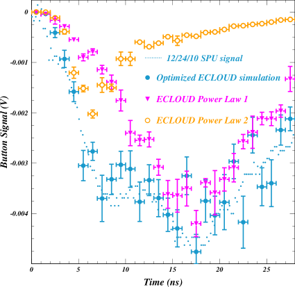
contributions to the modeled signal of each of the two power laws, as well as the result of a simulation including both contributions. The power laws are determined by the parameters , , and in the form . The level of consistency with the measured signal was obtained using a weight of 78% for a photoelectron energy distribution with peak energy 4 eV and , combined with a 22% contribution from a distribution with peak energy 80 eV and and .
Such detailed information on the photoelectron energy distribution applies only to photoelectrons produced by photons which have scattered sufficiently often to reach the bottom of the vacuum chamber. In contrast, the SPU measurements have not driven the need for such tuning of photoelectron energies produced at the primary source point on the radially outward wall of the vacuum chamber. Consistency with the observed cloud buildup is obtained with low-energy photoelectron production, such that the beam kick together with the intense space charge force due to the high concentration of electrons at the primary synchrotron radiation impact point dominate the kinetic energy distribution. Note also that the quantum efficiencies assumed for input parameters to the simulation are averages over the incident photon energy distribution, which is different for photons having undergone different numbers of reflections, so the ECLOUD input parameter definitions were generalized to allow three independent quantum efficiency values for photoelectrons: 1) those produced at the primary synchrotron radiation impact point on the radially outward side of the beam-pipe, 2) those produced at the point on the inward side of the beam-pipe opposite the primary impact point, where most absorbed photons have undergone a single reflection, and 3) those produced elsewhere. Finally, we checked that the introduction of high-energy components in the photoelectron energy distributions did not affect the level of agreement obtained previously with the coherent tune measurements, i.e. the tune shift modeling is insensitive to the photoelectron energy distribution for scattered photons.
4 Secondary Production Model
The SPU signal from a witness bunch provides sensitivity to the development of the cloud produced by the first bunch, including secondary electron production. The witness signal includes contributions from cloud electrons in the region between the beam and the bottom of the vacuum chamber, and so will be greater in magnitude and earlier than the signal from the leading bunch. The cloud population in the region of signal sensitivity depends directly on the kinetic energy of the cloud electrons, both the photoelectrons and the secondary electrons. At a time in the cloud development when a substantial fraction of the cloud electrons have undergone a single wall interaction, the energy distribution will be sensitive to the production energies of the true secondaries. At later times the cloud energy distribution is stabilized by the predominance of elastic wall interactions.
Figure 7 shows an example of the model sensitivity to the
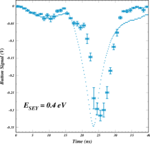
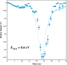
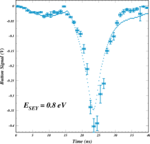
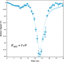
true secondary energy distribution. Two 5.3 GeV positron bunches of population separated by 28 ns provided the signal shown in the four figures, each of which also shows the ECLOUD model with differing assumptions for the true secondary production energy distribution. The distribution is parameterized as . The arrival time of the signal from the witness bunch sets a lower bound on the assumed value of with a sensitivity better than 0.2 eV.
We also found an upper limit on the parameter to be imposed by the late tail (40-80 ns after the bunch passage) of a single bunch SPU signal. Values below eV resulted in a broad late tail from photoelectrons produced on the outside of the vacuum chamber which is not observed in the measured signals. Since the sensitivity was again found to be about 0.2 eV, these two phenomena provide a remarkably tight constraint on the production energy distribution for true secondary electrons.
Such measurements of the time dependence of EC development afford discriminating power between the three components of the secondary yield model, since they are sensitive to the energy distribution in the cloud, and therefore to the relative probabilities of the types of wall interaction, each of which produces secondaries of characteristic energies. Figure 8 shows a typical example of the yield curve and emitted energy distributions of the secondary emission model implemented in ECLOUD.
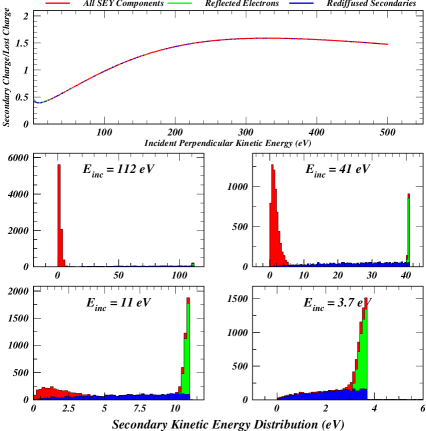
The secondary yield values in this example are typical of uncoated aluminum: 1.4, 0.2, and 0.4 for the true secondary, re-diffused and elastic processes, respectively. At low incident energy, the elastic process dominates, while the re-diffused contribution is independent of energy for energies greater than a few eV. The true secondary process dominates at high incident energy, and produces secondaries carrying only a few eV. The model includes an RMS smearing of 0.3 eV for the outgoing energies of the elastics. For purposes of comparison to the discussion in Ref. [13] the secondary electron energies are shown for incident energies of 112, 41, 11 and 3.7 eV.
We have found that the relative rate of re-diffused secondaries is constrained by the lifetime of the cloud produced by a single bunch as manifested in the tail of the SPU signal [14]. A model excluding the re-diffused process underestimates the EC lifetime from a single bunch with a sensitivity better than 10%. Measurements on a bare aluminum vacuum chamber were best matched with a re-diffused contribution of 20%, in quantitative agreement with the constraint provided by models of the CESRTA coherent tune shift data, where the omission of the re-diffused component resulted in an underestimate of the vertical tune shift increase in a strong dipole magnetic field along a train of 45 2.1 GeV bunches each carrying positrons [9].
5 Beam Conditioning Effects
The good reproducibility of the SPU measurements on a time scale of months has provided the ability to determine details of the beam conditioning process by observing the long-term time dependence of optimized model parameters. These studies are a subset of the in situ vacuum chamber comparisons in the same radiation environment (i.e. the same place in the CESR ring) for the case that the same chamber was left in place. The two regions in CESR equipped with SPU detectors differ in radiation environment, since the dominant source points are in dipole magnets of differing strengths. At 5.3 GeV, for example, the source dipole field is 3 kG (2 kG) in the west (east) region for a positron beam, resulting in a critical energy of 5.6 keV (3.8 keV). In addition, the distribution of reflected photons differs. By comparing SPU signals recorded at the same place in the ring with the same beam energy, bunch spacing and bunch population, many systematic contributions to the comparisons are avoided, and relatively simple changes to the modeling suffice to quantify the different properties of the vacuum chambers.
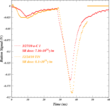
The first example of beam conditioning effects we studied was the case of an amorphous-carbon-coated aluminum chamber. Figure 9 shows signals recorded in May and December 2010 for two 5.3 GeV 28-ns-spaced bunches each carrying positrons, corresponding to a bunch current of 3 mA.
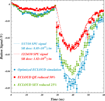
During the intervening time interval, CESR had operated at high current as an X-ray research facility, with the consequence that synchrotron radiation dose on the chamber had increased by a factor of about 20, from to /m. Also shown is the ECLOUD model optimized to reproduce the May measurement. Since conditioning affects the signals following each bunch similarly, we can conclude that the change is in the quantum efficiency rather than in the secondary yield. The December measurement is reproduced by a 50% decrease in the modeled quantum efficiency for photoelectron production. A reduction in the secondary yield of 25% is inconsistent with the observed effect, since the modeled leading bunch signal remains unchanged while the measured signal is clearly reduced.
In order to investigate the conditioning process for a chamber which had not seen any beam at all, we installed such a chamber in September, 2011, recording SPU measurements as soon as beam operations began. These measurements were then compared to measurements made in November. The synchrotron radiation dose between the two measurements increased from to /m, corresponding to an integrated beam dose increase of about to Amp-hours.
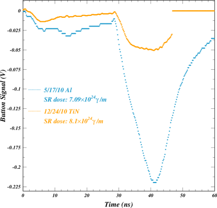
Figure 10 shows signals recorded with two 5.3 GeV 14-ns-spaced bunches each carrying positrons, corresponding to a bunch current of 3 mA.
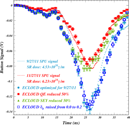
Between the two measurements the photon dose increased from to /m. Also shown is the ECLOUD model optimized to reproduce the September measurement. The November measurement is reproduced by a 50% decrease in the modeled quantum for photoelectron production. A reduction in the SEY of 50% is inconsistent with the observed effect, since the modeled leading bunch signal remains unchanged. Thus we conclude that the early conditioning process is similar to one previously measured in a well-conditioned chamber.
Figure 10 also shows the results of a model in which the yield value for the elastic component of the secondary yield has been increased from 0% to 20%. The modeled 14-ns signal is insensitive to such a change in the elastic yield. In contrast, the two-bunch signals for the case of 84-ns separation shown in Fig. 11
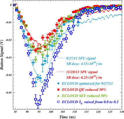
clearly show sensitivity to the elastic yield component, and exclude a value as high as 20%. Such a comparison permits the conclusion that the measurements are inconsistent with a conditioning effect in the elastic yield of 20%. Such low values for the elastic yield are characteristic of the amorphous carbon, diamond-like carbon, and TiN coatings, contrasting with a value closer to 50% required to match the SPU data for an uncoated aluminum chamber [12], as discussed in the next section.
6 EC Lifetime Studies
While the awareness of the sensitivity of the SPU measurements to the parameters of photoelectron production was largely motivated by inadequacies of the model discovered in its application to recent measurements, the original intended use of these time-resolved cloud measurements was to provide a quantitative estimate of the elastic yield parameter in the secondary electron yield model. A similar investigation was performed at RHIC [15]. The basic concept is that the mature cloud long after passage of any beam bunch is dominated by low-energy electrons which undergo primarily elastic interactions with the vacuum chamber wall.
Figure 12 shows an ECLOUD secondary yield population curve typical of the signal simulations for a carbon- or TiN-coated aluminum vacuum chamber.
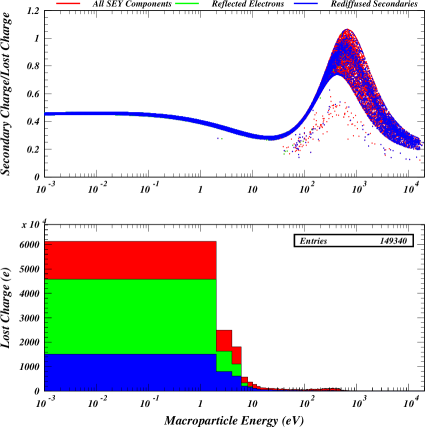
The true secondary yield maximum at 400 eV ranges from a minimum of 0.8 to a maximum of 1.1 owing to the dependence on incident angle. At low energy the yield value is dominated by the elastic interactions with the chamber wall. This case exhibits a total yield at low energy of 45%, of which 40% is elastic. Under the true secondary peak some cases are shown where ECLOUD generates two secondaries each carrying half the secondary charge in order to limit the maximum charge of a macroparticle.
Figure 13 shows how the witness bunch studies constrain the model parameter for the elastic yield .
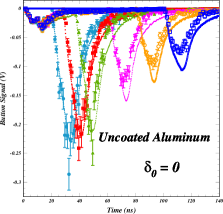
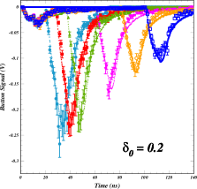
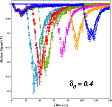

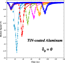
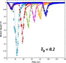
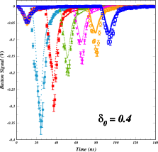
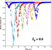
The upper row shows a scan of the modeled parameter for six two-bunch SPU signals with spacings of 20, 24, 36, 60, 80 and 100 ns. The two 5.3 GeV positron bunches each carry a population of . These signals were recorded in an uncoated aluminum chamber. The lower row shows a similar study for a TiN-coated chamber. In this case the each of the two positron bunches carries a population of and the spacings are 14, 28, 42, 56, 70 and 84 ns. The witness signals with longer delays between bunches clearly provide good discriminating power for the elastic yield, showing a sensitivity somewhat better than 20%. The optimal value of for the uncoated aluminum chamber is about 40%, consistent with the value of 50% used in the simulations which successfully modeled the CESRTA coherent tune shift measurements. In contrast, these witness-bunch measurements for a TiN-coated chamber exclude values for greater than 20%.
7 Installation of Time-resolved Retarding Field Analyzers
Time-resolved RFAs (TR-RFA) combine the properties of SPUs and retarding-field analyzers by providing signals with time resolution of about a nanosecond from a finely segmented collector array and a grid which can be biased to define variable sensitivity to cloud electron energy. Figure 14 shows the design of four TR-RFAs installed in the CESR ring in four custom vacuum chambers, each of which is located at the center of a chicane dipole magnet which can apply a field as high as 800 G.
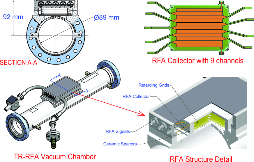
The middle grid is used to provide the retarding field. There are nine collectors etched on a kapton flex circuit, each connected to an SMA feed-through. The collectors are biased at +50 V to prevent secondary electrons from leaving the collector surface. The four chamber designs are chosen to study the EC mitigation techniques proposed for the ILC positron damping ring: TiN-coated and bare aluminum, each type with and without grooved lower and upper surfaces.
Two prototype TR-RFAs were installed in the chambers without grooves in 2012. A bias of +50 V was applied both to the retarding grid and the collectors during this test run. Initial results can be seen in Fig. 15,
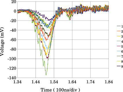
where the signal from the TR-RFA in the bare aluminum chamber is shown with and without a dipole field of 790 G. The beam in the storage ring consisted of a 10 bunch train of positrons at 5.3 GeV with 14 ns spacing. A witness bunch was also included at a delay of 112 ns following the train. Without magnetic field, collector 4 (near the horizontal center of the beam-pipe) exhibits the largest signal. When the field is turned on, all of the signals are reduced in amplitude, but collector 4 is reduced more than the others. This suppression of the central signal with magnetic field has also been seen in measurements with standard, time-integrating RFAs [16]. Such a vertical central depletion zone may be due to the effect of beam bunch kicks increasing the energies of the cloud electrons in the vertical plane of the beam to values exceeding the maximum of the true secondary yield curve [17, 18]. Thus model comparisons may provide sensitivity to the yield curve. Development of detector acceptance functions in magnetic fields will be important in this modeling project.
8 Summary
Time-resolved measurements of electron cloud buildup at CESRTA with good time resolution have shown remarkable discriminating power for the contributing physical processes, distinguishing photoelectron generation characteristics from those of secondary electron emission, as well as individually identifying the various types of secondary emission. The sensitivity to the kinetic energy distribution in the cloud constrains the production energy distributions of both photoelectrons and secondary electrons. The witness bunch method has provided detailed information on the in situ vacuum chamber comparisons, including beam conditioning information distinguishing changes in photoelectron emission from those of secondary emission.
This summer we installed unconditioned uncoated and TiN-coated aluminum vacuum chambers and recorded witness bunch data to be used in determining their early conditioning characteristics. Following the summer/fall operation as a high-intensity X-ray source, CESR will have a dedicated CESRTA data-taking period in November and December, allowing measurement of the uncoated and TiN-coated chambers. Four time-resolved retarding field analyzers have been installed in weak dipole magnets with uncoated and TiN-coated aluminum chambers both grooved and smooth. These will provide the first time-resolved measurements of cloud buildup in magnetic fields with fine transverse segmentation and variable cloud electron energy acceptance thresholds.
References
- [1] G.F. Dugan, M.A. Palmer, and D.L. Rubin, ILC Damping Rings R&D at CESRTA, ICFA Beam Dynamics Newsletter Nr. 50, eds. J. Urakawa and W. Chou (2009)
- [2] J.R. Calvey et al., Methods for Quantitative Interpretation of Retarding Field Analyzer Data, proceedings of ECLOUD’10, Cornell University (2010)
- [3] F. Zimmermann, G. Rumolo and K. Ohmi, Electron Cloud Build Up in Machines with Short Bunches, ICFA Beam Dynamics Newsletter Nr. 33, eds. K. Ohmi & M. Furman (2004).
- [4] J.R. Calvey et al., Electron Cloud Modeling Considerations at the CESR Test Accelerator, proceedings of PAC09, Vancouver, British Columbia, Canada (2009)
- [5] M.A. Furman and M.T.F. Pivi, Probabilistic Model for the Simulation of Secondary Electron Emission, Phys Rev ST-AB 5, 124404 (2002)
- [6] G. Dugan et al., Observations and Predictions at CESRTA, and Outlook for ILC, these proceedings
- [7] D.L. Kreinick et al., Application of Coherent Tune Shift Measurements to the Characterization of Electron Cloud Growth, proceedings of IPAC11, San Sebastian, Spain (2011)
- [8] D.L. Kreinick et al., Using Coherent Tune Shifts to Evaluate Electron Cloud Effects on Beam Dynamics at CESRTA, proceedings of ECLOUD’10, Cornell University (2010)
- [9] J.A. Crittenden et al., Progress in Studies of Electron-Cloud-Induced Optics Distortions at CESRTA, proceedings of IPAC10, Kyoto, Japan (2010)
- [10] J.A. Crittenden et al., Studies of the Effects of Electron Cloud Formation on Beam Dynamics at CESRTA, proceedings of PAC09, Vancouver, British Columbia, Canada (2009)
- [11] G.F. Dugan, S. Malishuk and D.C. Sagan, SYNRAD3D Photon Propagation and Scattering Simulation, proceedings of ECLOUD’10, Cornell University (2010)
- [12] J.A.Crittenden et al., Electron Cloud Modeling Results for Time-Resolved Shielded Pickup Measurements at CESRTA, proceedings of ECLOUD’10, Cornell University (2010)
- [13] R. Cimino et al., Can Low-Energy Electrons Affect High-Energy Physics Accelerators?, Phys.Rev.Lett. 93, Nr. 1, 014801-1 (2004)
- [14] J.P. Sikora et al., Electron Cloud Measurements Using Shielded Pickups at CESRTA, proceedings of IBIC 2012, Tsukuba, Japan (2012)
- [15] U. Iriso and G. Rumolo, Benchmarking Electron Cloud Data With Computer Simulation Codes, proceedings of EPAC06, Edinburgh, Scotland (2006)
- [16] J.R. Calvey et al., CESRTA Retarding Field Analyzer Measurements in Drifts, Dipoles, Quadrupoles and Wigglers, proceedings of IPAC10, Kyoto, Japan (2010)
- [17] F. Zimmermann, A Simulation Study of Electron-Cloud Instability and Beam-Induced Multipacting in the LHC , CERN LHC Project Report 95 (1997)
- [18] J.M. Jiminez et al., Electron Cloud with LHC-Type Beams in the SPS: A Review of Three Years of Measurements , CERN LHC Project Report 632 (2003)