Observation of particle pairing in a two-dimensional plasma crystal
Abstract
The observation is presented of naturally occurring pairing of particles and their cooperative drift in a two-dimensional plasma crystal. A single layer of plastic microspheres was suspended in the plasma sheath of a capacitively coupled rf discharge in argon at a low pressure of . The particle dynamics were studied by combining the top-view and side-view imaging of the suspension. Cross analysis of the particle trajectories allowed us to identify naturally occurring metastable pairs of particles. The lifetime of pairs was long enough for their reliable identification.
pacs:
52.27.Lw, 52.27.Gr, 36.40.MrI Introduction
A weakly ionized gas comprising dust or other fine solid particles is known as a complex, or dusty, plasma Ikezi:1986 ; Morfill:2009 ; Fortov:2005 . In experimental studies of complex plasmas the particle size is of a few nanometers to tens of microns. Immersed into a plasma, the particles charge up and interact with each other. It is a well-established fact that complex plasmas are able to self-organize, forming a highly ordered structure, plasma crystal, when the mutual interparticle interaction energy exceeds significantly their kinetic energy Thomas:1966 . In the presence of gravity, a single-layer, or two-dimensional (2D) plasma crystal can form. Last two decades of studies showed that plasma crystals can be exploited as a useful tool to model or at least mimic at a kinetic level many phenomena as diverse as particle and energy transport in solids and liquids, crystal layer plasticity, phase and structural transitions, etc. Morfill:2009 ; Fortov:2005 .
In plasma crystals, as in any other crystalline structures, point defects and dislocations are ubiquitous Nosenko:2008 ; Zhdanov:2011 . They may present an obstacle to performing some delicate experiments. Additionally, plasma crystals sometimes suffer from the presence of extra particles footnote:1 , which do not belong to the crystalline structure and can cause local instabilities and disturb the lattice. (Such particles are sometimes called “unstable”, “anomalous”, etc. or even, addressing their position in the flow of ions with respect to a particle layer, “upstream” or “downstream”, see, e.g., Ref. Du:2012 .) On the other hand, they can be successfully used, as the studies performed recently have shown, as an active agent in the plasma crystal heating experiments Schweigert:1996 ; Nunomura:2006 , as a convenient practical diagnostic tool allowing to test in the simplest way the complex plasma elasticity modules Samsonov:1999 ; Schwabe:2011 ; Lenaic:2012 , or as a probe of the plasma electric field distribution Kretschmer:2005 .
The particles which constitute the main lattice of a crystal are called intralayer particles. This terminology is also used in the granular media Combs:2008 and colloidal Patti:2009 physics. The particles located between the layers in multi-layer crystals Schweigert:1996 ; Pieper:1996 are naturally called the interlayer particles Patti:2009 ; Pieper:1996 .
The dynamics of interlayer particles are cardinally different from those of the intralayer particles. For example, the dynamics of a single second-layer Delrin particle Combs:2008 free to move on top of a granular dimer lattice, or the cooperative permeation of string-like clusters in colloids of rods Patti:2009 reveal unusual features. In plasma crystal studies, the particles moving in a plane above a single-layer plasma crystal (they were termed upstream particles in Ref. Du:2012 ) reveal elements of “strange kinetics” Shlesinger:1993 such as channeling and leapfrog motion Du:2012 .
The interaction of an upstream particle with the plasma crystal located beneath it (downstream of the ion flow) is strongly influenced by the ion wake. An ion wake is a build-up of positive space charge created behind a negatively charged particle by a flow of ions past it Lampe:2000 ; Melzer:2001 ; Steinberg:2001 ; Ivlev:2003 ; Lenaic:2009 ; kroll:2010 ; Woerner:2012 ; Morfill:2006 ; Hyde:2011 . Therefore, the wake-mediated interaction of an upstream particle with the plasma crystal is attraction-dominated Du:2012 .
A delicate repulsion-attraction balance can result in a strong correlation – pairing of the upstream particle with a neighboring intralayer one. To some extent, such kind of pairing resembles the famous Cooper electron pairs when the electron-phonon interactions produce a strong preference for singlet zero momentum electron pairs Cooper:1960 . Vertical pairing of two identical particles in the sheath of a rf discharge has been studied in Ref. Steinberg:2001 .
In this paper, we report on the first direct observation of particle pairing and dragging occurring under natural conditions in a 2D complex plasma. Neither a torque, as in the “rotating wall” technique of Refs. Nosenko:2009 ; Woerner:2012 , nor a laser beam, as in the laser-dragging experiment of Ref. Melzer:2001 , nor any other method of external manipulation has been used. Using paired particles as a probe of the mutual interparticle interaction is one more possibility that is briefly discussed in this paper.
II Experimental procedure
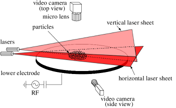
The experiments were performed in a modified version of the Gaseous Electronics Conference (GEC) rf reference cell Lenaic:2009 using argon at a pressure of Pa and melamine-formaldehyde microspheres with a diameter of m, a mass of , and a weight of , where is the free-fall acceleration on earth. A stylized sketch of the experimental setup is shown in Fig. 1. A weakly ionized plasma is generated by applying a forward rf power of W at MHz to the lower disk-shaped rf electrode (corresponding to the self-bias voltage V). The microparticles, introduced into the plasma using a dispenser, formed a stable monolayer confined in the plasma sheath above the rf electrode. Optical ports and windows at the top and the side of the chamber provide access for the laser illumination and recording systems. Two digital cameras (a Photron FASTCAM 1024 PCI operating at frames per second (fps) and a Basler Ace ACA640-100GM at fps) recorded the microparticle positions and their dynamics and provided top- and side-view snapshot sequences subjected further to a standard particle tracking technique Rogers:2007 ; Williams:2012 . Side-view imaging is usually used in 2D plasma crystal experiments only as a complementary diagnostic. In the present study, we relied on it for our main results. Therefore, we first verified the side-view data, using the fluctuation spectra of the particle out-of-plane motion, see Fig. 2, as a cross-check. Additionally, the side-view camera was used to verify that our experiments were carried out with a (dominantly) single layer of particles.
III Complex plasma parameters
The plasma crystal parameters were evaluated using a well-developed method based on the particle tracking technique Williams:2012 . The lattice constant was obtained from the first peak of the pair correlation function . The neutral gas damping rate was estimated to be Epstein:1924 . The small value of (compared to the characteristic frequency of the plasma crystal) assures weak frictional coupling of the particle dynamics to the ambient gas. Therefore, the particle motion is not overdamped and studying of the naturally occurring waves (fluctuations) can give reliable information about the lattice layer. The values of the particle charge , interaction range (where is the screening length), and the vertical confinement parameter were estimated from the fluctuation spectra of particle velocity Nunomura:2002 ; Zhdanov:2003 ; Zhdanov:2009 . These parameters are collected in Table 1 along with the parameter set adopted for numerical calculations performed for comparison reasons.
| parameter | top view | side view | theory |
|---|---|---|---|
| lattice constant, [m] | 500 | ||
| interaction range, | 1.06 | 1.06 | |
| particle charge, [] | 15.3 | ||
| vertical confinement | |||
| parameter, [Hz] | 25 | ||
| longitudinal phonon | |||
| speedδ, [mm/s] | 31 | ||
| transverse phonon | |||
| speedδ, [mm/s] | 6.5 |
α in the central part of the crystal, measuring ; β obtained from a row of particles that was well-aligned with the laser (left half of the top panel in Fig. 3); γ for the intralayer particles, assuming no decharging of particles by ion wakes; δ in-plane modes.
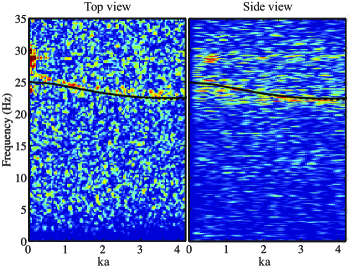
The experimental fluctuation spectra of the crystal obtained from either the top-view (TV) or side-view (SV) recording systems are shown in Fig. 2. Although both methods are widely used in complex plasma experimental studies (see, e.g., Liu:2010 ; Lenaic:2012 and the references therein), a cross-checking diagnostic has never been done before and the results of the TV and SV observations were never systematically compared. Below are important points of comparison that are worth to comment on: (i) the TV- and SV-spectra agree remarkably well with each other; (ii) the SV-spectra show systematically lower resolution in the wave numbers due to a significantly poorer spatial sampling rate; (iii) the SV-spectrum of the out-of-plane fluctuations is systematically lower (by about Hz) than the TV-spectrum most probably due to the fact that not exactly the same parts of the crystal are analyzed. It is also worth noting that the SV-spectra are not angle-resolved Liu:2010 . A more detailed comparison will be reported elsewhere.
The electric field in the discharge (pre)sheath is inhomogeneous with the characteristic length given by under our experimental conditions; here, a balance is assumed to be valid. Note that a dense lattice layer, consisting of highly charged microparticles, itself produces a finite electric field in its vicinity. In our conditions it is not large, though, about one fifth of in the mean-field approximation Totsuji:2001 .
IV Direct observation of the interlayer particle collisions
Upstream particles spontaneously moving above a 2D plasma crystal were reported for the first time in Ref. Du:2012 . Their impact on the dynamics of the crystal layer and some aspects of particle coupling were studied. These fast-moving particles, even if they remain invisible (since they stay outside of the illuminating laser sheet), could be recognized by the appearance of the attraction-dominated Mach cones in the lattice, a signature uniquely manifesting their presence in an experiment. However, a direct observation of the particle pairing process can only be done with the help of a side-view recording system, since the pairs tend to be extended in the vertical direction.
In our experiments, as in Ref. Du:2012 , a few upstream particles were wandering quasi-freely on top of the lattice layer along the channels made by the rows of ordered intralayer particles. From time to time, encountering a lattice imperfection blocking the channel, they strongly scattered and were forced to change the track direction, then moved again quasi-freely along another newly discovered path, and so on, covering a large area of the crystal. Usually, this process took quite a long time.
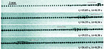
When an upstream particle happened to move in the vertical laser sheet, its trace was recorded by the side-view camera, as shown in Fig. 3. The travel path of an upstream particle is, on average, at the height of above the lattice layer (same as estimated in Ref. Du:2012 using a top-view survey). In all cases shown in Fig. 3, the interaction scenario appears to be quite universal, passing normally through the following well-distinguished phases: initiation, repulsion, binding, and dragging. When an upstream particle comes too close to the channel wall or encounters a point defect, a strong interlayer collision between the top particle and a nearby intralayer one occurs. The bottom particle drops a little, allowing the “intruder” to pass over it. Then the repulsion is apparently replaced by attraction. The bottom particle starts to behave as if it was seized by the intruder, tending to be dragged with it. Since both particles are negatively charged, this is puzzling to some extent. The newly formed pair continues drifting for a while until the next strong collision would break it up.
V Coupled pairs as quasi-particles
The association of two particles in a pair strongly affects the motion of both particles: They start to accelerate as if the momentum was not conserved during their collision, see Fig. 4. This kind of action-counteraction imbalance is not surprising at all keeping in mind the following. First, the binding and subsequent dragging of an intralayer particle, the follower, actually is a direct manifestation of the ion focus (localized positive spatial charge or the ion wake) formed beneath the top particle, which is in the upstream position in the pair. A negatively charged bottom particle footnote:4 is attracted by the ion focus while it is repelled by the negatively charged top particle Morfill:2009 ; Du:2012 . At the same time, the bottom particle continues to repel the top one whence accelerating it Schweigert:1996 . The forces working to produce this motion are the plasma forces Zhdanov:2005a .
Newly formed pairs behave as quasi-particles, which are (roughly) double-charged compared to the individual particles in the monolayer. This helps them to permeate through the lattice and to find an optimal path, e.g., inside a channel formed by the lattice particles, as the example shown in Fig. 4 (right panel) demonstrates.
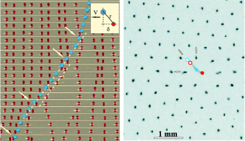
Upstream particles move non-uniformly along their trajectories. For instance, in Fig. 4 (left panel) the velocity of such a particle is about in the beginning and in the end of the travel path. However, it is more than twice larger, , when the particle becomes coupled, forming a close pair. This acceleration is due to the horizontal projection of the repulsion force between the coupled particles that is not completely canceled out. The average distance between the particles in the pair is , its horizontal projection (dragging distance) is . On average, the dragged particle in the pair is kept at the height below the monolayer equilibrium position, experiencing therefore an extra force of external confinement. This gives a useful estimate of the -component of the inter-pair repulsion force pressing it down: .
Given the approximately constant velocity of the pair, it is straightforward to roughly estimate the -component of the dragging force: . It is about times weaker compared to the vertical -component, in good agreement with that measured in Ref. Du:2012 . Following Refs. Woerner:2012 ; Fink:2012 , the coupling between the particles in a pair can be conveniently interpreted through Hooke’s spring constant. Introduced by the relationship , where is the dragging distance, it is , noticeably well in line with that reported in Refs. Woerner:2012 ; Fink:2012 .
It is also worth noting that the lifetime of a pair is short, e.g., about for the pairs shown in Fig. 4. Their formation time (as well as the decomposition time) is even shorter, about . Therefore, these processes are controlled by much stronger coupling forces producing accelerations of the order of , according to our estimates.
VI Conclusion
We have observed for the first time the spontaneously forming mobile pairs of coupled particles in a 2D plasma crystal. This phenomenon is different from previously reported channeling Du:2012 or “classical tunneling” Morfill:2006 . This observation was made possible by combined top- and side-view imaging of the dust particle suspension. We argue that the apparent self-acceleration of a particle pair is a direct consequence of the plasma wake effect. These naturally-occurring mobile pairs are metastable. They are, however, long-living enough for their reliable detection under our experimental conditions. The pairs we reported on in the present paper were formed by particles located initially at different heights. This helped to initialize the pairing process, because the mutual wake-mediated interaction was easily activated in this case. It is not strictly necessary for the particles to be initially at different heights, though. The pairing of particles is also possible, for instance, in the experimental situations when their vertical displacement becomes relatively large, thus enhancing the mutual wake-mediated interaction. Particle pairing is of primary significance in experimental studies of the later stages of the wake-mediated melting Lenaic:2009 , as our preliminary observations have demonstrated.
Acknowledgements.
This work was supported by the European Research Council under the European Union’s Seventh Framework Programme (FP7/2007-2013) / ERC Grant agreement 267499 and by the French-German PHC PROCOPE program (Project 28444XH).References
- (1) G. E. Morfill and A. V. Ivlev, Rev. Mod. Phys. 81, 1353 (2009).
- (2) V. E. Fortov, A. V. Ivlev, S. A. Khrapak, A. G. Khrapak, and G. E. Morfill, Phys. Rep. 421, 1 (2005).
- (3) H. Ikezi, Phys. Fluids 29, 1764 (1986); H. Thomas, G. Morfill, V. Demmel, J. Goree, B. Feuerbacher, and D. Möhlmann, Phys. Rev. Lett. 73, 652 (1994); Y. Hayashi and K. Tachibana, Jpn. J. Appl. Phys., Part 2 33, L804 (1994); J. Chu and I. Lin, Phys. Rev. Lett. 72, 4009 (1994).
- (4) H. Thomas and G. Morfill, Nature (London) 379, 806 (1996); H. Thomas, G. E. Morfill, V. Demmel, J. Goree, B. Feuerbacher, and D. Möhlmann, Phys. Rev. Lett. 73, 652 (1994).
- (5) V. Nosenko, S. Zhdanov, and G. Morfill, Phys. Rev. Lett. 99, 025002 (2007); V. Nosenko, S. Zhdanov, and G. Morfill, Phil. Mag. 88, 3747 (2008).
- (6) S. K. Zhdanov, M. H. Thoma, and G. E. Morfill, New J. of Phys. 13, 013039 (2011).
- (7) The term “extra particle” was used in Ref. Schweigert:1996 for a particle moving about in a plane beneath a monolayer in what the authors termed an “incomplete lower layer”.
- (8) C.-R. Du, V. Nosenko, S. Zhdanov, H. M. Thomas, and G. E. Morfill, Europhys. Lett. 99, 55001 (2012).
- (9) V. A. Schweigert, I. V. Schweigert, A. Melzer, A. Homann, and A. Piel, Phys. Rev. E 54, 4155 (1996); V. A. Schweigert, I. V. Schweigert, A. Melzer, A. Homann, and A. Piel, Phys. Rev. Lett. 80, 5345 (1998); V. A. Schweigert, I. V. Schweigert, V. Nosenko, and J. Goree, Phys. Plasmas 9, 4465 (2002).
- (10) S. Nunomura, D. Samsonov, S. Zhdanov, and G. Morfill, Phys. Rev. Lett. 96, 015003 (2006).
- (11) D. Samsonov, J. Goree, Z. W. Ma, A. Bhattacharjee, H. M. Thomas, and G. E. Morfill, Phys. Rev. Lett. 83, 3649 (1999); D. Samsonov, J. Goree, H. M. Thomas, and G. E. Morfill, Phys. Rev. E 61, 5557 (2000).
- (12) M. Schwabe, K. Jiang, S. Zhdanov, T. Hagl, P. Huber, A. V. Ivlev, A. M. Lipaev, V. I. Molotkov, V. N. Naumkin, K. R. Sütterlin, H. M. Thomas, V. E. Fortov, G. E. Morfill, A. Skvortsov, and S. Volkov, Europhys. Lett. 96, 55 001 (2011).
- (13) L. Couëdel, D. Samsonov, C. Durniak, S. K. Zhdanov, H. M. Thomas, G. E. Morfill, and C. Arnas, Phys. Rev. Lett. 109, 175001 (2012).
- (14) M. Kretschmer, S. A. Khrapak, S. K. Zhdanov, H. M. Thomas, G. E. Morfill, V. E. Fortov, A. M. Lipaev, V. I. Molotkov, A. I. Ivanov, and M. V. Turin, Phys. Rev. E 71, 056401 (2005).
- (15) K. Combs, J. S. Olafsen, A. Burdeau, and P. Viot, Phys. Rev. E 78, 042301 (2008).
- (16) A. Patti, D. El Masri, R. van Roij, and M. Dijkstra, Phys. Rev. Lett. 103, 248304 (2009).
- (17) S. Ogata and S. Ichimaru, Phys. Rev. Lett. 62, 2293 (1989); J. B. Pieper and J. Goree, Phys. Rev. Lett. 77, 3137 (1996); K. Yang, Phys. Rev. Lett. 87, 056802 (2001).
- (18) M. F. Shlesinger, G. M. Zaslavsky, J. Klafter, and G. Morfill, Nature 363, 31 (1993).
- (19) M. Lampe, G. Joyce, G. Ganguli, and V. Gavrishchaka, Phys. Plasmas 7, 3851 (2000).
- (20) V. Steinberg, R. Sütterlin, A. V. Ivlev, and G. Morfill, Phys. Rev. Lett 86, 4540 (2001).
- (21) A. Melzer, Plasma Sources Sci. Technol. 10, 303 (2001).
- (22) A. V. Ivlev, U. Konopka, G. Morfill, and G. Joyce, Phys. Rev. E 68, 026405 (2003).
- (23) G. E. Morfill, U. Konopka, M. Kretschmer, M. Rubin-Zuzic, H. M. Thomas, S. K. Zhdanov, and V. Tsytovich, New J. Phys. 8, 7 (2006).
- (24) L. Couëdel, V. Nosenko, S. K. Zhdanov, A. V. Ivlev, H. M. Thomas, and G. E. Morfill, Phys. Rev. Lett. 103, 215001 (2009).
- (25) M. Kroll, J. Schablinski, D. Block, and A. Piel, Phys. Plasmas 17, 013702 (2010).
- (26) Jie Kong, Truell W. Hyde, Lorin Matthews, Ke Qiao, Zhuanhao Zhang, and Angela Douglass, Phys. Rev. E 84, 016411 (2011).
- (27) L. Wörner, C. Räth, V. Nosenko, S. K. Zhdanov, H. M. Thomas, G. E. Morfill, J. Schablinski, and D. Block, Europhys. Lett. 100, 35001 (2012).
- (28) L. N. Cooper, American Journal of Physics 28, 91 (1960).
- (29) V. Nosenko, A. V. Ivlev, S. K. Zhdanov, M. Fink, and G. E. Morfill, Phys. of Plasmas 16, 083708 (2009).
- (30) S. S. Rogers, T. A. Waigh, X. Zhao, and J. R. Lu, Physical Biology 4, 220 (2007).
- (31) J. D. Williams, E. Thomas, Jr., L. Cou edel, A. V. Ivlev, S. K. Zhdanov, V. Nosenko, H. M. Thomas, and G. E. Morfill, Phys. Rev. E 86, 046401 (2012).
- (32) D. Samsonov, S. Zhdanov, and G. Morfill, Phys. Rev. E 71, 026410 (2005).
- (33) S. K. Zhdanov, A. V. Ivlev, and G. E. Morfill, Phys. Plasmas 16, 083706 (2009).
- (34) P. S. Epstein, Phys. Rev. 23, 710 (1924).
- (35) S. Nunomura, J. Goree, S. Hu, X. Wang, A. Bhattacharjee, and K. Avinash, Phys. Rev. Lett. 89, 035001 (2002).
- (36) S. Zhdanov, S. Nunomura, D. Samsonov, and G. Morfill, Phys. Rev. E 68, 035401(R) (2003).
- (37) B. Liu, J. Goree, and Y. Feng, Phys. Rev. Lett. 105, 085004 (2010); ibid, 105, 269901 (2010).
- (38) H. Totsuji, C. Totsuji, and K. Tsuruta, Phys. Rev. E 64, 066402 (2001).
- (39) The standard blend function of Mathcad 14.0 was used. Blending is useful in substracting and rebiasing backgrounds.
- (40) Note that the charge of the lower particle in a pair is not the same as for the intralayer particles due to decharging of particles by ion wakes, see, e.g., J. Carstensen, F. Greiner, L.-J. Hou, H. Maurer, and A. Piel, Phys. Plasmas 16, 013702 (2009).
- (41) S. K. Zhdanov, A. V. Ivlev, and G. E. Morfill, Phys. Plasmas 12, 072312 (2005).
- (42) M. A. Fink, S. K. Zhdanov, M. H. Thoma, H. Höfner, and G. E. Morfill, Phys. Rev. E 86, 065401(R) (2012).