Transmission properties of one dimensional metal and left-handed gratings
Abstract
We provide rigorous numerical calculations (using the rigorous coupled-wave analysis) of transmission spectra of various metallic and metamaterial one-dimensional gratings and identify plasmonic resonances responsible for enhanced transmission. We argue that the most important mechanism which influences the resonant transmission is the coupling of incident electromagnetic wave with two plasmonic waves: lengthwise plasmons, which propagates along the grating, and crosswise plasmons excited in air gaps.
pacs:
73.20.Mf, 78.66.Bz, 81.05.Xj, 41.20.JbI INTRODUCTION
Surface plasmon economou ; maier represents the basic eigenmode of a metallic grating. Thanks to the spatial periodicity of the grating, surface plasmons could be excited by incident electromagnetic (EM) wave. The interaction of these two waves (surface plasmon and incident wave) strongly influences the transmission properties of the periodic grating. Enhanced transmission of EM waves through periodic metallic gratings has been experimentally observed in Ref. ebbesen . Contrary, for very thin metallic gratings, transmission is smaller due to the absorption of plasmon energy braun . Negative role of surface plasmons is also discussed in Ref. lalanne .
In this paper, we calculate the transmission of EM waves through various one-dimensional (1D) gratings and show that observed resonant frequency behavior of the transmission can be explained as an interaction of incident wave with excited plasmonic resonances. We distinguish two kinds of plasmons porto ; ros . The first one, lengthwise (LW) plasmon, which propagates along the grating surface and can be excited only when Bragg’s relation between the wave vector of surface plasmon and grating period is fulfilled maier ; zayats . These LW plasmons are also responsible for the extraordinary transmission through a single aperture, if the incident surface is periodically corrugated lezec . LW plasmon resonance appears as a sharp Fano-type peak in the spectrum. The second one, crosswise (CW) plasmon, is excited inside the gaps takakura ; lee . CW plasmon resonance appears as a broad Fabry-Perot type maximum in the spectrum. We provide quantitative estimation of resonant frequencies for both plasmons and show that they are in good agreement with rigorously calculated transmission resonances.
The Paper is organized as follows: In Section II the transmittance of the EM wave through a metallic grating, calculated with the use of the rigorous coupled wave analysis (RCWA) rcwa , is presented. In order to reveal the effect of grating geometry (grating thickness, grating period, width of gap), transmittance is calculated for different grating parameters. In Section III, observed resonances in the transmission spectra are interpreted as a coupling effect of incident EM wave with the surface plasmons excited on the surface of the structure or inside it. Section IV deals with the application of the model to left-handed material gratings. Discussion of obtained results is given in Section V.
II Transmission spectra
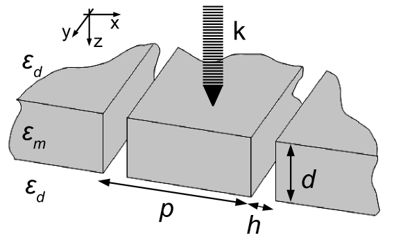
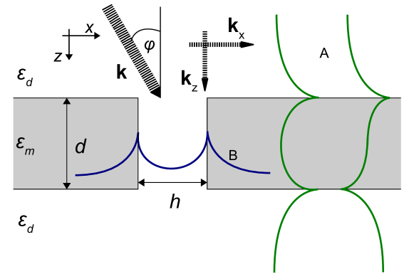
The reference 1D metallic grating is shown in Fig. 1. The grating is uniformly extended in the -direction. Its thickness in the -direction is and its spatial period in the -direction is . The width of air gap is . The metallic relative permittivity is . The embedding medium is air with relative permittivity . The relative permittivity of the metal is given by the Drude’s formula
| (1) |
where is the plasmon frequency and is the absorption coefficient. For our calculations THz and THz, typical for Ag and Au metals .
Numerical simulations of the transmission were realized with our own numerical program based on the RCWA. In the RCWA, the structure is divided into multiple sandwiched layers along the direction of propagation. The permittivity is a periodic function of in each sublayer. The numerical calculation involves spatial Fourier expansion of the EM field and of the dielectric function in each sublayer of the structure. The EM field determined by the RCWA satisfies Maxwell’s equation within each sublayer as well as the boundary conditions between adjacent layers. The numerical accuracy is only limited by the number of orders used in the Fourier expansion. The typical number of Fourier modes we used is 106. If not stated otherwise, the incident electromagnetic plane wave is normal to the grating plane and the vector of magnetic field is parallel to the -direction (TM polarization).
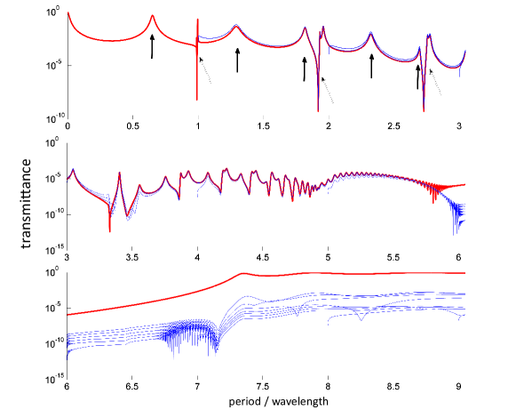
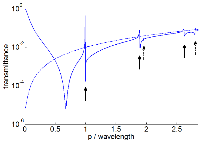
Figure 2 shows the calculated transmission coefficient against the normalized frequency . There are two types of enhanced transmission. The first one is a Fabry-Perot resonance (five lowest resonances at , 1.30, 1.82, 2.32) are marked by arrows in Fig. 2. The second type, Fano resonances fan , observed at , 1.92, 2.73, etc. are marked by dashed arrows. Both resonances are present in all of the diffracted orders’ transmission.
To identify the physical origin of these resonances, we gradually change one of the parameters of the structure and investigate how the transmission spectrum changes compared to the reference one shown in Fig. 2.
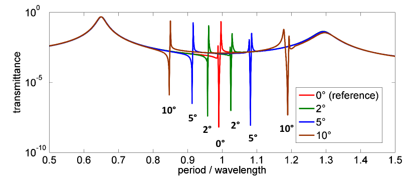
Figure 3 shows how the transmission spectra changes when the angle of incidence (in the plane) increases from (this is the reference curve from Fig. 2) to , and . While the Fabry-Perot transmission maxima have not changed, Fano resonances split to two separate frequencies which strongly depend on the incident angle.
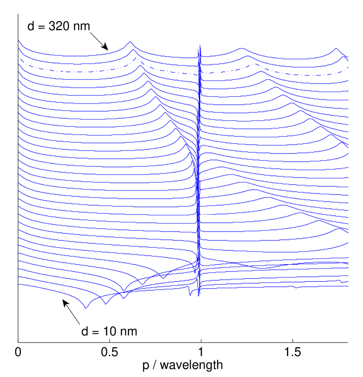
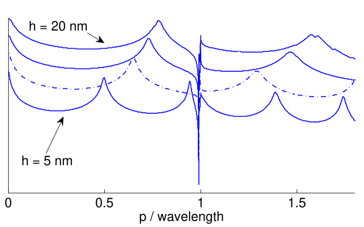
Transmission spectra for various grating thicknesses are shown in Fig. 4. The position of the first Fabry-Perot type maximum increases for decreasing thickness . On the other hand, the position of the first Fano resonance hardly depends on . It is interesting to see how the Fabry-Perot peak interacts with the Fano resonance. The “travelling” Fabry-Perot peak actually transforms to Fano type peak and back. After further decreasing grating thickness a transmission minimum appears on interval .
Similarly, a changing air gap width affects the position of Fabry-Perot type maximum (Fig. 5) while sharp Fano peaks remain unaffected.
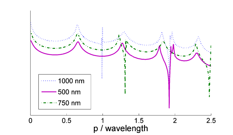
Finally, we probe transmission against the grating period . As it is seen in Fig. 6, position of Fabry-Perot maxima is left unchanged and the sharp Fano resonances are shifted to the right for decreasing grating period and become less sharper.
III Theoretical framework
In this section we present an interpretation of the origin of enhanced transmission phenomenon. We show that Fano-type sharp peaks are caused by the interaction of incident EM wave with surface plasmons propagating along the surface of the metallic grating. The excitation of these lengthwise (LW) plasmons is possible thanks to the spatial periodicity of the grating. Similarly, Fabry-Perot-type resonances are due to crosswise (CW) plasmons excited and guided along the air gap resonators (Fig. 7).
III.1 Lengthwise plasmons
Consider a homogeneous metallic slab with thickness and negative relative permittivity given by the real part of Eq. 1. The metal slab is surrounded by dielectric relative permittivity . The dispersion relation for the TM polarized surface waves excited on both sides of the metal-dielectrics interface is given economou ; markos ; maier as
| (2) |
for the symmetric plasmon, and
| (3) |
for the antisymmetric one. Parameters and determine exponentially decreasing intensity of the EM field by the distance from the metal-air interface:
| (4) |
| (5) |
Here, is the wave vector of the incident wave in vacuum and is the -component of the plasmon. Since is positive, Eq. 5 would be satisfied only if for . This is not achievable solely by the incident ( is the angle of incidence), therefore the grating periodicity is required to modulate :
| (6) |
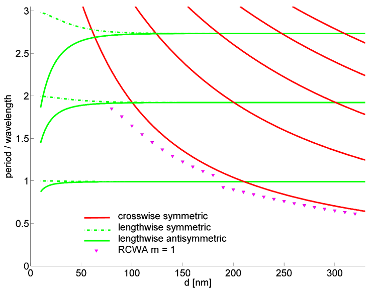
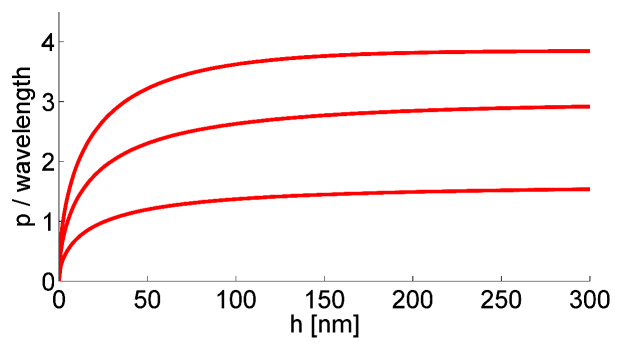
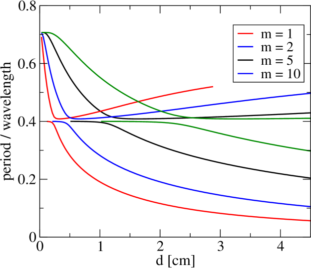
Using Eqs. (2-6) we numerically obtain the positions of lengthwise plasmon resonances for different integers versus the slab thickness . Results are plotted in Fig. 8 for normal incidence.
As it follows from Eq. 6, the position of the LW resonance strongly depends on the angle of incidence and period . On the other hand, the dependence on the thickness is weak, at least for sufficiently large . However, air gap width has some effect on this resonance since it changes the effective relative permittivity of the metallic grating (Fig. 5).
Considering these observations of numerical data from transmission spectra (Figs. 3, 6 and 4) we conclude that Fano-type sharp resonances are generated by lengthwise plasmons propagating on interfaces along the grating. Evidently, lengthwise plasmon resonance creates negative transmission effect in conjunction with Ref. lalanne . In contrast to Ref. lalanne we can not confirm that these resonances are closely related to diffraction orders. Although the first two sharp resonances are close to the positions of diffracted orders (because the dispersion curve of the plasmon lies very close to the light cone ), higher order resonances are not connected to higher diffracted orders (see Table 1).
III.2 Crosswise plasmons
Crosswise plasmon resonance propagates across the grating along the interfaces of air gap (see Fig. 7). Corresponding equations are similar to that for LW plasmons:
| (7) |
for the symmetric mode and
| (8) |
for the antisymmetric mode. Again, and determine exponential decrease of the EM field by the distance from the air-metal interface
| (9) |
| (10) |
The wave vector in the direction, , is given by a Fabry-Perot resonance condition
| (11) |
III.3 Identifying plasmon resonances
We use the presented model for the identification of numerically calculated resonances. Calculated resonant frequencies, summarized in Tables 1 and 2 confirm that there is a very good agreement between rigorous calculations and the model.
| m | lengthwise | RCWA | crosswise | RCWA |
|---|---|---|---|---|
| 1 | 0.99 | 0.99 | 0.70 | 0.65 |
| 2 | 1.92 | 1.92 | 1.36 | 1.29 |
| 3 | 2.73 | 2.73 | 1.93 | 1.82111Can not be clearly determined because it overlaps a lengthwise plasmon resonance. |
| 4 | 3.33 | 3.38 | 2.34 | 2.32 |
| 5 | 3.86 | 3.85 | 2.79 | 2.701 |
| m | RCWA | lengthwise plasmon222CW plasmon resonance is not dependent on . | |
|---|---|---|---|
| 0 | 1 | 0.99 | 0.99 |
| 1 | 1.03 | 1.02 | |
| 0.96 | 0.96 | ||
| 1 | 1.08 | 1.08 | |
| 0.91 | 0.91 | ||
| 1 | 1.19 | 1.19 | |
| 0.85 | 0.85 |
For grating thickness nm symmetric and antisymmetric LW plasmon resonances are barely distinguishable. To test the theory, we calculate the transmission spectra for thickness nm (Fig. 10). Now, the first () symmetric and antisymmetric LW plasmon should appear at 0.98 and 1.00, respectively. The second and the third antisymmetric and symmetric modes are clearly distinguishable at 1.86 and 1.96 () and 2.58 and 2.84 (). This agrees with observed positions of antisymmetric LW resonances (1.00, 1.90 and 2.62) and symmetric LW resonances (1.96 and 2.80). Apparently, the first symmetric resonance is suppressed by the first antisymmetric resonance.
Apart from plasmonic resonances, we observe a transmission dip at wavelength . The position of this dip depends on the width of the air gap and on the thickness of the grating. The incoming EM wave stops to interact with the metallic grating for frequencies below this dip, thus the transmission increases to unity for the limit .
IV Left-handed material gratings
In this Section we apply the previous theory to the transmission of EM wave through periodic grating made of left-handed metamaterial (LHM). We characterize the metamaterial by the frequency dependent permittivity and magnetic permeability using the model described in markos . The permittivity is given by Eq. (1) but with plasma frequency GHz and absorption GHz. Frequency dependent permeability is given by the relation
| (12) |
used for the description of the effective permeability of periodic array of split-ring resonators srr . The resonant magnetic frequency GHz and filling factor . The grating possesses a transmission band within the frequency interval
| (13) |
Bellow and above this transmission band, the metamaterial behaves as a metal with frequency dependent positive magnetic permeability.
Figure 11 shows the dispersion curves of three surface plasmons propagating along the interface LHM - air ruppin ; markos . Since the permeability of the LHM is negative on frequency interval , a TE polarized surface wave might also be excited.
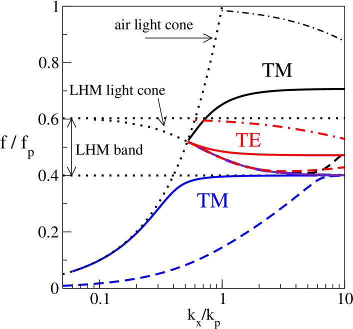
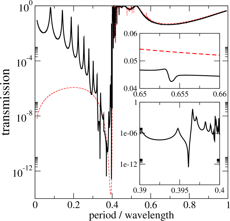
Figure 12 presents the frequency dependent transmission through the LHM grating. As expected, transmission is close to unity within the LHM transmission band (Eq. 13). Nevertheless, we observed strong Fano resonances here (not clearly visible in the Fig. 12) due to the coupling of incident EM wave with LW guided waves shadrivov propagating along the air-LHM-air structure in the -direction and -direction. For the TM modes, the dispersion curves are
| (14) |
for the symmetric and antisymmetric modes, respectively. Here,
| (15) |
and
| (16) |
for the LHM and air, respectively. The value of is given by Eq. 6.
On the frequency region we observe a series of transmission maxima which could be identified as Fabry-Perot resonances based on the excitation of CW plasmons inside air gaps. Since the thickness of the grating is rather large (), we observe large number of CW plasmons (Fig. 13). These plasmonic resonances exist also in the transmission band (Eq. 13). Above the transmission band, CW plasmons cause weak oscillations of the transmission (not visible in Fig. 12).
For the TM polarization, we identify two LW plasmon resonances at wavelengths and . The latter is less pronounced since the exponential decay of plasmon is very slow . We have not succeeded to identify the TE LW plasmon resonance, expected at , because the transmission of the TE wave also fluctuates in the LHM band (Eq. 13) due to excitations of CW plasmons.
V Conclusions
We have shown that enhanced transmission phenomena for periodic metallic gratings are caused by two clearly distinguishable plasmon resonances, namely lengthwise and crosswise plasmon resonances. Lengthwise plasmons (symmetric or antisymmetric) propagate along the two interfaces induced by the grating period. Crosswise plasmons propagate inside the air gaps. Only symmetric CW plasmons were observed. In the metallic gratings, the frequency of antisymmetric CW plasmons is much higher for a narrow air gap, and in the LHM gratings, antisymmetric CW plasmons lie very close to the LHM transmission band (Fig. 11).
For completeness, we note that another excitations exist in the air gap, namely the guiding modes with both components of the wave vector, and , real inside the gap. However, similarly to antisymmetric CW plasmons in metallic gratings, the frequency of these excitations is not accessible neither for metallic nor for the LHM gratings.
Our analysis does not consider the role of the absorption, which is given by the small absorption parameter in the frequency-dependent permittivity. Good agreement of transmission data with the prediction of the model indicates that for these parameters the transmission does not play significant role in the propagation of EM wave.
We have shown that plasmon resonance does not rely on diffracted orders but solely on the dispersion relation of propagating plasmons. Our rigorous calculations were used to prove the validity of a simple model of propagating plasmons. This simple model can be used to identify the type of enhanced transmission phenomenon (lengthwise or crosswise plasmon resonance) and to design various metal filters with subwavelength features which support enhanced transmission.
This work was supported by the Slovak Research and Development Agency under the contract No. APVV-0108-11 and VEGA Agency, project No. 1/0372/13.
References
- (1) E. N. Economou, Phys. Rev. 182, 569 (1969);
- (2) S. A. Maier, Plasmonics: Fundamentals and Applications Springer Science (2002).
- (3) T. W. Ebbesen, H. J. Lezec, H.F. G haemi, T. Thio, P. A. Wolff, Nature 391, 667 (1998); H. F. Ghaemi, T. Thio, D. E. Grupp, T. W. Ebbesen and H. J. Lezec, Phys. Rev. B 58, 6779 (1998).
- (4) J. Braun, B. Grompf, G. Kobiela, M. Dressel, Phys. Rev. Lett. 103, 203901 (2009).
- (5) Q. Cao and Ph. Lalanne, Phys. Rev. Lett. 88, 057403 (2002).
- (6) J. A. Porto, J. García-Vidal, J. B. Pendry, Phys. Rev. Lett. 83, 2845 (1999).
- (7) A. Roskiewicz and W. Nasalski, J. Phys. B: At. Mol. Opt. Phys. 46, 025401 (2013).
- (8) A. V. Zayats, I. I. Smolyaninov and A. A. Maradudin, Phys. Rep. 408, 131 (2005).
- (9) H. J. Lezec et al., Science 297, 820 (2002); L. Martin-Moreno, F. J. García-Vidal, H. J. Lezec, A. Degiron, and T. W. Ebbesen, Phys. Rev. Lett. 90, 167401 (2003).
- (10) Y. Takakura, Phys. Rev. Lett. 86, 5601 (2001).
- (11) K. G. Lee and Q-Han Park, Phys. Rev. Lett. 98, 103902 (2005).
- (12) J. J. Hench and Z. Strakoš, Electron. Trans. Num. Anal. 31, 331 (2008).
- (13) I. El-Kady et al., Phys Rev. B 62, 15299 (2000).
- (14) Fan, Shanhui, Wonjuoo Suh, and J. D. Joannopoulos, J. Opt. Soc. Am. A 20, 569–572 (2003).
- (15) P. Markoš and C. M. Soukoulis, Wave Propagation (Princeton University Press, Princeton, 2008).
- (16) J. B. Pendry et al., IEEE Trans. Microwave Theory Tech. 47, 2075 (1999).
- (17) N. Engheta and R. W. Ziolkowski (Eds.) Metamaterials Willey-Interscience (2006).
- (18) R. Ruppin, Phys. Lett. A 277, 63 (2000); J. Phys.: Condens. Matt. 13, 1811 (2001).
- (19) I. V. Shadrivov, A. A. Sukhorukov, and Yu. S. Kivshar, Phys. Rev. E 67, 057602 (2003).