High-quality multi-GeV electron bunches via cyclotron autoresonance
Abstract
Autoresonance laser acceleration of electrons is theoretically investigated using circularly polarized focused Gaussian pulses. Many-particle simulations demonstrate feasibility of creating over 10-GeV electron bunches of ultra-high quality (relative energy spread of order ), suitable for fundamental high-energy particle physics research. The laser peak intensities and axial magnetic field strengths required are up to about W/cm2 (peak power PW) and 60 T, respectively. Gains exceeding 100 GeV are shown to be possible when weakly focused pulses from a 200-PW laser facility are used.
pacs:
52.38.Kd, 37.10.Vz, 42.65.-k, 52.75.Di, 52.59.Bi, 52.59.Fn, 41.75.Jv, 87.56.bdI Introduction
Particle accelerators are an indispensable tool to explore the fundamental laws of nature and are widely used for medical and industrial applications. At the frontier of accelerator technology is the Large Hadron Collider (LHC), a gigantic circular machine of 27 km total circumference lhc . The need to control the size and cost of building such machines have kept alive the quest for alternative means to accelerate particles. Over the past decade, laser plasma-based acceleration has emerged as a promising candidate R. A. Snavely et al. (2000); A. J. Mackinnon et al. (2001); S. Karsch et al. (2003); L. Romagnani et al. (2005); B. M. Hegelich et al. (2006); H. Schwoerer et al. (2006); robson2007 . In particular, laser wakefield acceleration of electrons mangles2004 ; leemans2004 ; faure2004 has undergone rapid development. Stable and reproducible beams have been realized faure2006 and particle kinetic energies at the GeV level have been reached leemans2006 . Furthermore, the creation of a plasma wave from interaction with a highly energetic electron beam as a driver allows for doubling the kinetic energy of the accelerated particles within a meter-scale plasma wakefield accelerator blumenfeld2007 ; leemans2009 ; leemans2009phystoday .
The advent of quasi-static magnetic fields lanl1 ; lanl ; dresden ; florida1 ; florida2 of durations up to seconds, with strengths as high as 100 Tesla, suggests vacuum autoresonance laser acceleration (ALA) (see loeb1986 ; sal2000 and references therein) as a further potential alternative to conventional acceleration. The ALA mechanism employs a static magnetic field oriented along the propagation direction of the laser. Thus, the underlying concept of ALA stems from the realization that an electron continues to absorb energy from a circularly polarized laser field if it is launched in cyclotron autoresonance with it. For the case of laser fields described by plane-waves sal2000 resonance is essentially between the Doppler-shifted laser frequency seen by the electron and the cyclotron frequency of the electron around the lines of the applied static magnetic field. Feasibility of post-acceleration of electrons to kinetic energies of about three times their initial energies has also been theoretically investigated, employing continuous-wave CO2 laser fields described within the paraxial approximation hirshfield2000 .
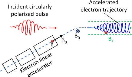
In this paper, the ALA configuration (see Fig. 1) is investigated over a wide range of laser and magnetic field parameters. Our results, stemming from single- and many-particle calculations which employ pulsed and focused laser fields, indicate electron energy gains of several hundred (even thousand) times the initial injection energy. For magnetic field strengths below 60 Tesla, energy gains in excess of 10 GeV are shown to be possible. It is shown that the gains are attained over distances less than 10 m, and from a near-infrared laser system of peak intensity W/cm2 (peak power PW). Many-particle simulations also demonstrate that an electron bunch of high quality (relative energy spread on the level) may be obtained, taking Coulomb particle-particle repulsions into account in simulations at densities of cm-3. Gains in excess of 100 GeV are also shown to be possible anticipating a 200-PW laser system, like it might be realized by the Extreme Light Infrastructure (ELI) eli . Our work is motivated by currently feasible magnetic fields of strength of the order of 100 Tesla lanl1 ; lanl and anticipates continued progress in high magnetic field research.
II Basic equations
Classical electron motion in the presence of electromagnetic fields and is governed by the Lorentz-Newton equations of motion, namely,
| (1) |
which describe time evolution of the particle’s relativistic momentum and energy , respectively. In the above, is the magnitude of the charge of the electron and is its rest mass, is the speed of light in vacuum, is the particle’s velocity scaled by , and SI units are used throughout. Results to be presented below are based on solving these equations numerically for single- and many-particle systems. In the solutions, the electron is assumed to be overcome by the front of the pulse at at the origin of a coordinate system whose axis is oriented along the direction of pulse propagation.
In earlier calculations of autoresonance acceleration the laser fields were modeled as plane-waves of infinite extension in space and time sal2000 , or as those of a continuous beam within the paraxial approximation hirshfield2000 . The plane-wave-based calculations have led to the realization of the resonance condition, to be recalled below, and have shown that an electron stands to gain more energy from circularly polarized light than from light of the linear polarization variety. Recall that the polarization vector of a circularly polarized plane wave rotates about the direction of propagation at the angular frequency of the wave, while its field strength remains constant. Thus, if the initial conditions are such that the electron cyclotron frequency matches the Doppler-shifted frequency (sensed by the electron) of the circularly polarized fields, the electron will subsequently surf on the wave and continue to absorb energy from it. Hence, calculations in this paper will employ circularly polarized laser fields, obtained by the superposition of two linearly polarized fields, with perpendicular polarization vectors and a -phase difference Y. I. Salamin (2007). A pulse shape is introduced by multiplying the fields by the Gaussian envelope , where is the phase variable, is the wavenumber, is the envelope’s full-width-at-half-maximum, and is the pulse duration (temporal full-width-at-half-maximum). For the field amplitudes, a generalized Lax series representation (in powers of the diffraction angle , where is the beam’s waist radius at focus) will be adopted lax ; davies ; Y. I. Salamin (2007). Thus, the fields of the ALA scheme may be written as (see Y. I. Salamin (2007) for definitions of the symbols and more details)
| (2) | |||||
and
| (3) | |||||
where the primed components follow from the unprimed ones by letting and adding a phase-shift of .
III The fields
To decide the order of the correction terms, beyond the paraxial approximation, which ought to be retained in the various field expressions, simulations have been performed for a single electron injected axially with 50 MeV initial kinetic energy. The electron’s exit energy gain as a function of the pulse waist radius at focus has been analyzed, when terms up to , where , are employed in modeling the laser fields (see Fig. 2). The simulation results for terms of highest order and coincide, demonstrating that terms of order higher than may be dropped, as expected, since .
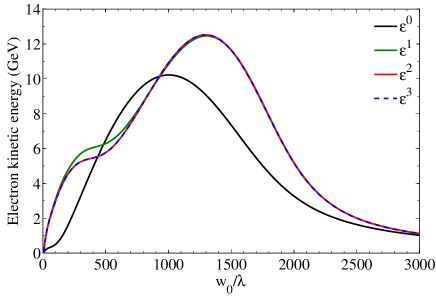
Due to the large focus radius, the longitudinal component influences the ALA dynamics only negligibly and the energy gain results essentially from interaction with the transverse field component. This is shown in analytical calculations in sal2000 for purely transverse fields. For the parameters used (see caption of Fig. 3), the exit energy gain peaks for a waist radius at focus . The maximum electron exit energy gain attained in this case is GeV. The peak is reached for a focus large enough to allow for optimal autoresonance to occur, but still tight enough to guarantee a sufficiently strong field ().
IV Cyclotron Autoresonance
From the plane-wave calculations sal2000 we learn that, for autoresonance to occur, the uniform magnetic field, to be applied axially and added to the laser magnetic field in the equations of motion, should be calculated from
| (4) |
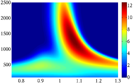
where is the laser frequency, and is the initial speed of the electron scaled by . Introduction of a pulse-shape and a tight focus is expected to modify the resonance condition (4) and render it approximate at best, thus leading to a slight deterioration in the electron-beam quality. To investigate this issue, the applied axial magnetic field is replaced by and the parameter space, spanned by and , is scanned for optimum exit energy gains. The results are displayed in Fig. 3; a contour plot of the exit energy gain vs. both the beam waist radius at focus and the employed static magnetic field . The plot shows clearly a region in parameter space for which the exit energy gain is optimal. The exit energy gain is not sensitive to small fluctuations in the ALA configuration parameters. For example, an energy gain of about 11 GeV may be realized for waist radii in the range extending roughly from 950 to 1750 and a magnetic field strength in the approximate range 1.04 to 1.13. The maximum energy gain of 12.5 GeV is reached for T. Recent progress in quasi-static magnetic field research has achieved 45 T florida1 ; florida2 ; lanl over a distance of 0.225 m. Thus, the 58 T goal may not be too far-fetched, and the need to have such a magnetic field strength over 25 m may, in principle, be met by employing an assembly of such magnets. However, such a stacking of magnets will be experimentally difficult to realize and the generated fringe fields at the interface between two magnets will probably have negative impact on the energy resolution.
To continuously maintain a magnetic field strength of about 60 T over 10 m for one second would require an average power consumption of 2.25 GW lanl . However, a petawatt laser provides its energy in a pulsed way, such that we do not need to continuously maintain the magnetic field which will significantly lower the average energy consumption as we will show subsequently. For one relativistic electron bunch at approx. the speed of light it takes about 33.3 ns to travel 10 m and, hence, for ten bunches about 0.3 s. This implies that at a laser repetition rate of 10 shots per second the energy consumption of the ALA scheme corresponds to only 0.7 kJ based on pulsed magnets. Since this value does not include the power consumption of the laser system and the LINAC, it exceeds in total the power consumption of laser wakefield accelerators martins2010 ; welsh2012 . Moreover, we want to emphasize that this estimate is based on the assumptions that the magnets are able to operate at such short pulses and their power consumption scales linearly with the magnets’ pulse duration, which might be influenced by the presence of pedestals.
V ALA dynamics
V.1 Single-particle calculations
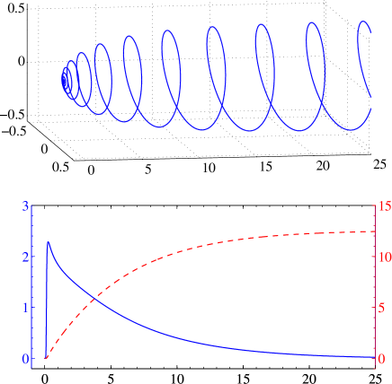
For further insight into the ALA dynamics, Fig. 4(a) shows the 3D trajectory of a single electron, accelerated using the optimal parameters of and . Note that the transverse dimensions are enlarged in Fig. 4(a) giving the impression that the trajectory is a helix with increasing radius. However, the radius of the helix hardly increases beyond the first 9 m of axial excursion, over which the pitch of the helix increases rapidly, thus rendering the trajectory essentially linear. In Fig. 4(b) the corresponding exit energy gain (red dashed line) is shown as a function of the axial excursion distance. After an initial (approximately linear) increase, the energy gain starts to saturate with increasing excursion. The accelerating phase seems to be limited within the initial axial excursion, after which interaction with the transverse electric field components diminishes as the particle gets left behind the pulse. For the set of parameters used (see caption of Fig. 3) the 10-GeV level is reached after a 9.14-m axial excursion. Moreover, the acceleration gradient is plotted vs. the axial excursion (blue line). The maximal acceleration gradient of 2.286 GeV/m is reached at m. This exceeds the gradient of conventional LINACs (100 MeV/m) by more than one order of magnitude. By contrast, wakefield accelerators reach gradients of 10-100 GeV/m leemans2006 . However, it should be emphasized that in single-stage wakefield accelerators the acceleration distance is typically m, yielding energy spreads of the order of leemans2004 .
V.2 Many-particle simulations
The single-particle calculations, whose results have been presented above, will now be supported by many-particle simulations. Dynamics of a bunch of electrons injected along the -axis into the ALA configuration, as well as the beam properties of the accelerated electrons, are considered next. An ensemble of electrons, considered to be non-interacting for now, randomly distributed within a volume of cylindrical shape centered about the coordinate origin and oriented along the -axis, is used to model an electron bunch, along the lines of our earlier work in Y. I. Salamin, Z. Harman, C. H. Keitel (2008); sal-pra2011 ; li . The incident laser pulse accelerates particles at the left end of the cylinder first, followed by particles farther to the right. The cylinder containing the electrons has a length mm and a radius mm.
The initial kinetic energy of the electrons follows a normal distribution with mean value MeV and spread (standard deviation) MeV lee . Such an electron bunch may be pre-accelerated using a short LINAC or a table-top betatron, and then guided by a magnetic field for axial injection (see Fig. 1). Employing the laser system parameters of Fig. 3 and the optimal waist radius , the resulting exit energy gain distribution of an ensemble of 15000 electrons has a mean exit energy gain of GeV and a spread of MeV (). The transverse beam emittance amounts to mm mrad which compares well with what is obtained from conventional accelerators lee .
Dependence of the electron exit kinetic energy distribution on fluctuations in the initial kinetic energy distribution has been studied. Employing a bunch with MeV changes the mean exit energy gain to GeV, and its spread to GeV ().
V.3 Particle-particle interaction effects
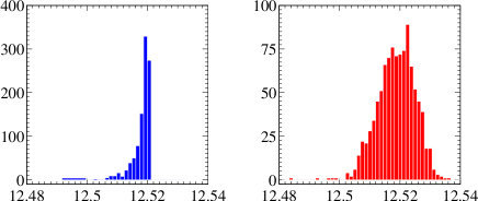
To investigate the role of electron-electron interaction effects a suitable model has to be developed. A conventional particle-in-cell scheme describes the interaction of a laser with an initially neutral plasma, and is not applicable over macroscopic distances of several meters. Therefore, further simulations have been performed employing a 1000-particle ensemble confined to a spatial volume similar to what has been used above, but scaled to render the particle density the same as would be obtained from a -particle bunch (typical in conventional particle accelerators slac-pub ) with the Coulomb interactions turned on galow and off. The resulting exit energy gain distributions are shown in Fig. 5. In the non-interacting ensemble case Fig. 4 (a) the mean exit energy gain amounts to GeV with a spread of MeV (). For the interacting ensemble Fig. 4 (b) the energy spread approximately doubles ( GeV, MeV ()). Furthermore, spatial spreading of the bunch (not shown here) is increased by a few percent as a result.
Since the relative velocities of electrons in the center-of-mass of the bunch are low (), higher-order relativistic particle-particle interaction effects galow can be neglected. To ensure that the reduced size of the ensemble does not play a role we performed the simulations for an interacting ensemble of 500 particles at the same density. Bearing in mind the different random initial conditions, a mean exit energy gain of GeV with a spread of MeV () has been obtained, which is in good agreement with the values given above for the 1000-particle ensemble. Hence, validity of the calculational method is confirmed and the long-range interaction effects have been treated appropriately.
VI Discussion
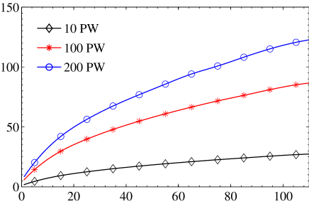
The examples discussed thus far have been concerned essentially with a single set of laser parameters, soon to be available for laboratory experiments. Even more powerful laser systems may be available in the near future eli . In search of parameter sets that may lead to much higher energy gains, useful for particle physics research, single-particle calculations have been performed whose results are displayed in Fig. 6. The figure shows, e.g., that a gain of about 100 GeV may be reached employing a 75-fs pulse, focused to and derived from a 200-PW laser system (corresponding to a peak intensity W/cm2) eli . However, this will come at a price to be paid in terms of the size of such a facility, and a uniform magnetic field T to be maintained along around 400 m. To lower the required magnetic field strength one may inject the electrons at a higher initial velocity, as can be seen from Eq. (4).
For electrons accelerated to tens of GeV energy or above, the question of whether radiation reaction effects play a role may arise. However, simulations based on the Landau-Lifshitz equation landau have also been carried out which revealed that the electron dynamics is only marginally influenced by radiation reaction. This agrees well with the finding that, at intensities below W/cm2, radiation reaction effects are negligible antonino .
VII Summary and conclusions
It has been demonstrated, in single- and many-particle simulations, that electrons may be accelerated to multi-GeV
energies, if launched into cyclotron autoresonance with a circularly polarized laser pulse, and employing parameters for the laser and required uniform magnetic
field that are currently available, or under construction. Similar simulations have also been shown to lead to over 100-GeV electron energy gains from envisaged
laser pulses eli . In all cases considered, the energy gradients exceed the known limits of conventional accelerators by at least one order of magnitude.
Dedicated many-particle simulations reveal ultra-low relative energy spreads of the order of comparable with conventional accelerator and storage facilities
lee and suitable for high-precision particle
physics experiments.
However, we want to recall that the parameters used in this theoretical study
particularly for the employed magnetic field strengths over long distances are out of the scope of near-future
experiments.
Acknowledgements.
BJG acknowledges discussions with T. V. Liseykina, A. Di Piazza and M. Tamburini, BJG and JXL acknowledge hospitality at the American University of Sharjah (UAE) where part of this work was done, and YIS acknowledges support from the German Alexander von Humboldt Stiftung in Bonn. The work of ZH has been supported by the Alliance Program of the Helmholtz Association (HA216/EMMI).References
- (1)
- (2) LHC - The Large Hadron Collider, http://lhc.web.cern.ch/lhc/.
- R. A. Snavely et al. (2000) R. A. Snavely et al., Phys. Rev. Lett. 85, 2945 (2000).
- A. J. Mackinnon et al. (2001) A. J. Mackinnon et al., Phys. Rev. Lett. 86, 1769 (2001).
- S. Karsch et al. (2003) S. Karsch et al., Phys. Rev. Lett. 91, 015001 (2003).
- L. Romagnani et al. (2005) L. Romagnani et al., Phys. Rev. Lett. 95, 195001 (2005).
- B. M. Hegelich et al. (2006) B. M. Hegelich et al., Nature 439, 441 (2006).
- H. Schwoerer et al. (2006) H. Schwoerer et al., Nature 439, 445 (2006).
- (9) L. Robson et al., Nat. Phys. 3, 58-62 (2007).
- (10) S. P. D. Mangles et al., Nature 431, 535 (2004).
- (11) C. G. R. Geddes et al., Nature 431, 538 (2004).
- (12) J. Faure et al., Nature 431, 541 (2004).
- (13) J. Faure et al., Nature 444, 737 (2006).
- (14) W. P. Leemans et al., Nat. Phys. 2, 696 (2006).
- (15) I. Blumenfeld et al., Nature 445, 741 (2007).
- (16) E. Esarey, C. B. Schroeder, and W. P. Leemans, Rev. Mod. Phys. 81, 1229 (2009).
- (17) W. P. Leemans and E. Esarey, Phys. Today 62, 44 (2009).
- (18) J. Singleton et al., Physica B 346-347, 614 (2004).
- (19) Los Alamos National Laboratory - press release, http://www.lanl.gov/news/releases/magnetic_field_researchers_target_hundred_tesla_goal.html and see also http://www.lanl.gov/orgs/mpa/nhmfl/ and http://www.lanl.gov/orgs/mpa/nhmfl/60TLP.shtml.
- (20) J. Wosnitza et al., J. Magn. Magn. Mater. 310, 2728 (2007).
- (21) H. J. Schneider-Muntau, A. V. Gavrilin, and C. A. Swenson, IEEE Trans. Appl. Supercond. 16, 926 (2006)
- (22) M. D. Bird et al., IEEE Trans. Appl. Supercond. 19, 1612 (2009).
- (23) A. Loeb and L. Friedland, Phys. Rev. A 33, 1828 (1986).
- (24) Y. I. Salamin, F. H. M. Faisal, C. H. Keitel, Phys. Rev. A 62, 053809 (2000).
- (25) J. L. Hirshfield, and C. Wang, Phys. Rev. E 61, 7252 (2000).
- (26) The Extreme Light Infrastructure, http://www.extreme-light-infrastructure.eu.
- (27) M. Lax, W. H. Louisell, and W. B. McKnight, Phys. Rev. A 11, 1365 (1975).
- (28) L. W. Davis, Phys. Rev. A 19, 1177 (1979).
- Y. I. Salamin (2007) Y. I. Salamin, Appl. Phys. B 86, 319 (2007).
- (30) Martins et al., Nature Physics 6, 311-316 (2010).
- (31) Welsh et al., JOURNAL OF PLASMA PHYSICS 78, 393-399 (2012).
- Y. I. Salamin, Z. Harman, C. H. Keitel (2008) Y. I. Salamin, Z. Harman, C. H. Keitel, Phys. Rev. Lett. 100, 155004 (2008).
- (33) Z. Harman, Y. I. Salamin, B. J. Galow, and C. H. Keitel, Phys. Rev. A 84, 053814 (2011).
- (34) Jian-Xing Li, Y. I. Salamin, B. J. Galow, and C. H. Keitel, Phys. Rev. A 85 063832 (2012).
- (35) S. Y. Lee, Accelerator physics, 2nd ed. (World Scientific, Singapore, 2004).
- (36) C. L. O’Connel et al., SLAC-PUB-11195 (May 2005).
- (37) B. J. Galow, Z. Harman, C. H. Keitel, Opt. Express 18, 25950 (2010).
- (38) L. D. Landau and E. M. Lifshitz, The Classical Theory of Fields (Elsevier, Oxford, 1975).
- (39) A. Di Piazza, C. Müller, K. Z. Hatsagortsyan, C. H. Keitel, Rev. Mod. Phys. 84, 1177 (2012).