Scalable quantum computing based on stationary spin qubits in coupled quantum dots inside double-sided optical microcavities111Published in Sci. Rep. 4, 7551 (2014).
Abstract
Quantum logic gates are the key elements in quantum computing. Here we investigate the possibility of achieving a scalable and compact quantum computing based on stationary electron-spin qubits, by using the giant optical circular birefringence induced by quantum-dot spins in double-sided optical microcavities as a result of cavity quantum electrodynamics. We design the compact quantum circuits for implementing universal and deterministic quantum gates for electron-spin systems, including the two-qubit CNOT gate and the three-qubit Toffoli gate. They are compact and economic, and they do not require additional electron-spin qubits. Moreover, our devices have good scalability and are attractive as they both are based on solid-state quantum systems and the qubits are stationary. They are feasible with the current experimental technology, and both high fidelity and high efficiency can be achieved when the ratio of the side leakage to the cavity decay is low.
pacs:
03.67.Lx, 42.50.Ex, 42.50.Pq, 78.67.HcQuantum logic gates are the basic elements to realize quantum computation and quantum information processing. It is well known that the controlled-not (CNOT) gate is one of the most efficient quantum gates. CNOT gates supplemented with single-qubit rotations are widely adopted as the standard model of universal quantum computation uni ; uni1 ; uni2 ; uni3 ; uni4 . It has been shown that the synthesis of a general two-qubit gate requires 3 CNOT gates and 15 elementary one-qubit rotations in the worst case 3CNOT1 ; 3CNOT2 ; 3CNOT3 . The “small-circuit” structure for two-qubit gates in terms of CNOT gates has been well solved small . In experiment, a single-qubit gate is easily implemented by a local Hamiltonian or an external field, while the two-qubit operations highly depend on the physical systems and there are more demanding and imperfection to implement them. That is, it is interesting to investigate the implementation of the two-qubit CNOT gate in specific physical systems.
The implementation of multi-qubit gates is an important milestone for a scalable quantum computing. However, the realization of a generic multi-qubit gate is quite worse in terms of CNOT gates and single-qubit rotations, and the implementation of a two-qubit gate in a multi-qubit system is usually more complex than that in a two-qubit system. In 2004, Shende et al. 3CNOT3 gave the theoretical lower bound for multi-qubit gates, , in terms of CNOT gates. However, up to now, the “small-circuit” structure and the specific synthesis of the logic gates for multi-qubit systems are two open questions. Among the three-qubit gates, many efforts have been made in studying the fundamental Toffoli gate which is not only a universal gate for classical computing but also for quantum computing book ; Toffoli . Together with Hadamard gates, Toffoli gates form a universal set of quantum gates for quantum computation Toffoli . Moreover, Toffoli gate is a central building block in some quantum cryptography protocols, phase estimation, and some quantum algorithms. The optimal CNOT-gate cost of a Toffoli gate Toffolicost is 6. Fewer resources and simpler quantum circuits are desired for an efficient quantum computation. It is thus desirable to seek simpler schemes to directly implement Toffoli gate.
Although many interesting protocols have been proposed to construct universal quantum gates, it is still a big challenge to implement quantum gates in experiment. The ones based on solid-state quantum systems are especially attractive because of their good scalability and stability. Quantum dot SWAP (QD) is one of the promising candidates for a solid-state qubit, due to the modern semiconductor technology and the microfabrication technology. The long electron-spin decoherence time (s) of a QD by using spin-echo techniques cohertime1 ; cohertime2 ; cohertime3 , nanoscale confinement of electrons nanoscale1 ; nanoscale2 , the preparation of the QD-spin superposition state superposition1 ; superposition2 , the QD-spin detection techniques spin-detection , and the electron-spin manipulation using picosecond/femtosecond optical pulses spin-manipulate1 ; spin-manipulate2 ; spin-manipulate3 ; spin-manipulate4 make an electron spin in a QD an excellent candidate for the qubit in solid-state quantum computation. In 2008, Hu et al. Hu1 ; Hu2 proposed a device, an excess electron confined in a self-assembled In(Ga)As QD or a GaAs interface QD placed inside a single-sided or a double-sided optical resonant cavity. Many interesting tasks have been carried out on this quantum system Hu3 ; Hu4 ; Hu5 ; Hu6 ; Appli1 ; weicnot ; RenLPL ; RenSR ; WeiOEphoton ; Appli2 ; repeater ; Ren ; wangtjhbsa . For example, utilizing this system, Hu et al. Hu3 ; Hu4 built a controlled-phase gate with a polarization photon as the control qubit and an electron spin as the target qubit. Bonato et al. Appli1 constructed a hybrid CNOT gate with an electron spin as the control qubit and a polarization photon as the target qubit. Also, a hybrid CNOT gate with a polarization photon as the control qubit and an electron spin as the target qubit was proposed recently weicnot . In 2013, Ren et al. RenLPL proposed a scheme for a photonic spatial-polarization hyper-controlled-not gate assisted by a QD inside a one-sided optical microcavity. In 2014, Ren and Deng RenSR presented a scheme for the hyper-parallel photonic quantum computation with coupled QDs. The scheme for the CNOT gate on two photonic qubits WeiOEphoton was presented in 2013. A scheme Appli2 for entanglement purification and concentration of electron-spin entangled states and a quantum repeater scheme repeater based on QD spins in optical microcavities were introduced in 2011 and 2012, respectively.
In this paper, we investigate the possibility to achieve a compact
and scalable quantum computing based on stationary electron-spin
qubits. We construct two important universal quantum gates on
electron-spin systems, including the two-qubit CNOT gate and the
three-qubit Toffoli gate, by using the giant optical circular
birefringence induced by the electron spins in QDs confined in
double-sided optical microcavities as a result of cavity quantum
electrodynamics (QED). We give the compact quantum circuits and the
detailed processes for implementing these universal quantum gates.
The qubits of our gates are encoded on two orthogonal electron-spin
states of the excess electrons confined in QDs inside optical
resonant microcavities, denoted by and
. A polarized single photon, denoted by
or , plays a medium role. After the
input-output process of the single photon, the measurement on the
polarization of the output photon and some proper single-qubit
operations are performed on the electron-spin qubits, the evolutions
of these universal quantum gates are accomplished with the
probability of 100% in principle. Our protocols have some features.
First, our quantum circuits for the universal quantum gates are
compact and economic, and they reduce the resources needed and the
errors as they do not require additional electron-spin qubits, just
a flying photon. Second, the double-sided QD-cavity system easily
reaches a large phase difference () between the uncoupled
cavity and the coupled cavity Hu2 , while it is a hard work in
a single-sided QD-cavity system. Third, our gates allow for a
scalable and stable quantum computing as the qubits for the gates
are confined in solid-state quantum systems. Fourth, our schemes
work in a deterministic way if the photon loss caused by the optical
elements (such as half-wave plates, and polarizing beam splitters)
and the detection inefficiency are negligible. Fifth, our schemes
are feasible with current technology. Both a high fidelity and a
high efficiency for each gate can be achieved when the ratio of the
side
leakage to the cavity decay is low.
Results
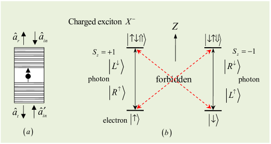
Giant optical circular birefringence. We exploit the optical property Hu1 ; Hu2 ; Hu3 ; Hu4 of the QD-cavity system to complete our schemes for implementing the CNOT gate and the Toffoli gate on electron spins. The schematic diagram for a QD-cavity system, a singly charged In(Ga)As QD or a GaAs interface QD placed at the antinode of a resonant double-sided optical microcavity with two symmetric and low loss partially reflective mirrors in the top and the bottom Hu2 , employed in our protocols, is shown in Fig. 1(a). The negatively charged exciton (trion, ), which consists of two electrons and one heavy hole trion , is the fundamental optical excitation, and it is essential for optical transitions in a QD-cavity system. There are two kinds of spin-dependent optical transitions, shown in Fig. 1(b). The photon in the state or () couples to the dipole for the transition from to , and the photon in the state or () couples to the dipole for the transition from to . Here the superscript arrows of () indicate their propagation direction of the photon along the normal direction of the cavity axis and the circular polarization of the photons are dependent of their propagation direction. and represent the two heavy-hole spin states with the -direction spin projections and , respectively. and represent the electron-spin states with the -direction spin projections and , respectively.
The change of the input photon state in the QD-cavity system can be obtained by solving the Heisenberg equations of motion for a QD-cavity system Heisenberg
| (1) |
and the input-output relation for the cavity
| (2) |
The specific expression of the reflection and the transmission coefficients of a realistic QD-cavity system is Hu2 :
| (3) |
Here, , , and are the frequencies of the cavity, the input photon, and the transition, respectively. and are the cavity field operator and the dipole operator, respectively. g is the coupling strength between and the cavity mode. , , and are the cavity decay rate, the side leakage (unwanted absorption) rate, and the dipole decay rate, respectively. and are the two input field operators, and and are the two output field operators. and are the noise operators related to reservoirs. is taken for a weak excitation approximation.
The complex reflection (transmission) coefficient given by Eq.(3) indicates that the reflected (transmitted) light encounters a phase shift. When the QD is in the state , the or light feels the hot cavity () and gets a phase shift with the flip of the photon polarization and the photon propagation direction after reflection, whereas the or light feels the cold cavity () and gets a phase shift with the photon polarization and the photon propagation direction unchanged after transmission. In the case that the QD is in the state , the or light feels the cold cavity and gets a phase shift after transmission, whereas the or light feels the hot cavity and gets a phase shift after reflection. The phase shift or can be adjusted by the frequency detuning (). When considering the interaction with , that is, the QD is resonant with the cavity and the spin of the independent electron is connected by the resonant single photon, the reflection and the transmission coefficients for the uncoupled cavity (called a cold cavity, g=0) and the coupled cavity (called a hot cavity, ) can be simplified as
| (4) |
and for the uncoupled cavity, and and for the coupled cavity can be achieved in the strong coupling regime in experiment by adjusting when (the ideal cavity) and . That is, if the photon couples to , it will be reflected by the cavity and both the propagation and the polarization of the photon are flipped. If the photon does not couple to , it will transmit the cavity and acquire a mod phase shift relative to a reflected one Hu2 ; Appli1 . Therefore, the rules of the input photon can be summarized as follows Appli1 :
| (5) |
The photon spin remains unchanged upon the reflection as the circular polarization of the photons is dependent of their propagation direction, so and with the same , and with .
Compactly implementing CNOT gate on a two-qubit electron-spin system. Now, let us describe the construction of a deterministic CNOT gate on the two stationary electron-spin qubits assisted by double-sided QD-cavity systems. It flips the target qubit if and only if (iff) the control qubit is in . That is,
| (9) |
in the basis . Here is a identity matrix. Suppose the two remote electrons confined in cavities 1 and 2 are initially prepared in the state
| (10) |
The subscript represents the control qubit confined in cavity 1 and stands for the target qubit confined in cavity 2.
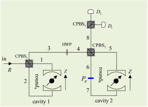
Our schematic diagram for a CNOT gate on the two stationary electron-spin qubits is shown in Fig. 2. The input single photon in the state transmits the polarizing beam splitter in the circular basis CPBS1 to the spatial mode 1 and injects into cavity 1 which induces the transformations and . The subscript () of () represents the spatial mode from which the photon is emitted. CPBS can be constructed by a PBS in the horizontal and vertical basis followed by a half-wave plate (HWP) at 22.5∘. Subsequently, the photon in the state or is led to the spatial mode 3 by CPBS1 which completes the transformations and . That is, rounda transforms the state of the whole system composed of the two excess electrons inside cavities 1 and 2 and the single photon from the initial state to . Here
| (11) |
| (12) |
The transformations of rounda can be described by the following unitary matrix:
| (17) |
in the basis , , , . Before the photon in the state or arrives at CPBS2 simultaneously, a Hadamard operation is performed on it (i.e., let it pass through the HWP whose optical axis is set at 22.5∘) and an operation is performed on the excess electron inside cavity 2 before and after the photon interacts with the QD in cavity 2. Here an operation completes the transformations
| (18) |
and an operation completes the transformations
| (19) |
The operations () induce the state of the whole system to be
| (20) |
Here roundb completes the transformation
| (21) |
From Eq.(20), one can see that if the output photon is in the state , the CNOT gate is accomplished. If the output photon is in the state , after a feed-forward single-qubit operation is performed on the QD in cavity 1, the CNOT gate is accomplished as well. That is, after the measurement on the output photon and the feed-forward operation on the QD, the state of the two-electron system becomes
| (22) |
Therefore, the quantum circuit shown in Fig. 2 converts
the input state to the output state
, i.e.,
.
It implements a deterministic electron-spin CNOT gate which flips
the state of the target electron-spin qubit when the control
electron-spin qubit is in the state ; otherwise,
nothing is done on the target qubit.
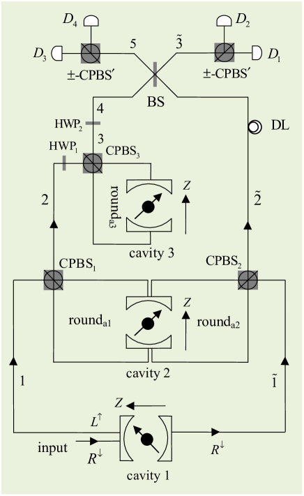
Toffoli gate on a three-qubit electron-spin system. The schematic diagram of our scheme for compactly implementing a three-qubit electron-spin Toffoli gate is shown in Fig. 3. It implements a NOT operation on the target qubit iff both the two control qubits are in . That is, the unitary transformation of the Toffoli gate on the three QDs can be characterized by the following matrix
| (26) |
in the basis . Here is a identity matrix. Suppose the spins of the three excess electrons in cavities 1, 2, and 3 are encoded as the first control, the second control, and the target qubits, respectively. The system composed of those three electrons is initially prepared in the state
| (27) |
Our protocol for a Toffoli gate can be achieved with three steps discussed in detail as follows.
First, a single photon in the state is injected into the input port, shown in Fig. 3. If the photon is transmitted through cavity 1, it is emitted from the spatial mode with the state . If the photon is reflected by cavity 1, it is emitted from the spatial mode 1 with the state . The nonlinear interaction between the input photon and the QD in cavity 1 transforms the state of the composite system composed of the three electrons (, and ) and the single photon into
| (28) |
When the photon is emitted from the spatial mode 1, it will be injected into rounda1 described by Eq.(17). When the photon is emitted from the spatial mode , it will be injected into rounda2 described by Eq.(17). Rounda1 and rounda2 transform the state of the whole system into
| (29) |
The photon emitting from the spatial mode does not interact with the QD in cavity 3, while the photon emitting from the spatial mode 2 is injected into cavity 3. Before and after the photon emitting from the spatial mode 2 interacts with the QD in cavity 3, an is performed on it with HWP1 and HWP2, and an is performed on the electron in cavity 3, respectively. Operations () transform the state of the whole system into
| (30) |
Second, the photon emitting from the spatial mode 4 interferes with the photon emitting from the spatial mode at the 50:50 beam splitter (BS) which completes the transformations
| (31) |
Third, the output photon is measured in the basis . After some feed-forward single-qubit operations are performed on the electron-spin qubits, a Toffoli gate on the three-qubit electron-spin system is achieved. That is, the state of the system composed of the three electrons confined in QDs becomes
| (32) |
Here, the response of detector indicates that the Toffoli gate is successful. The response of detector indicates that the feed-forward single-qubit operations and should be performed on the QDs in cavities 1 and 2, respectively. The response of detector () indicates that should be performed on the QD in cavity 2 (1).
From Eq.(32), one can see that the quantum circuit shown in Fig. 3 converts the input state to the output state , i.e., . That is, it can be used to implement a Toffoli gate on a three-qubit electron-spin system, which flips the state of the target electron-spin qubit iff both the two control electron-spin qubits are in the state , in a deterministic way.
Discussion
We have discussed the construction of universal quantum gates on electron-spin qubits, assisted by double-sided optical microcavities. In above discussion, all the QD-cavity systems are ideal. That is, the side leakage of the cavities is not taken into account. However, there inevitably exists the side leakage (which includes the material background absorption and the cavity loss) in a realistic QD-cavity system, which induces the polarize-bit-flip errors and different amplitudes between the coupled and the uncoupled photons. If the cavity leak is taken into account, the optical selection rules employed in our work become Hu2 ; Appli1
| (33) |
QDs inside microcavities with high quality factors are of particular interest for studying light-matter interaction. The photon loss strongly reduces . In micropillar microcavities, a drop of takes place with the pillar diameter due to an increasing photon loss observe2 . It is desired to increase the values but maintain a small effective optical mode volume, which can be achieved by improving the sample design, growth, and structure observe2 . Some coupling strengths and the quality factors of the QD-cavity system have been experimentally achieved in various microcavities and nanocavities observe2 ; observe1 ; observe3 ; observe4 ; Largesize (see Tab. 1).
| coupled strength | quality factor | parameters |
|---|---|---|
| observe1 | ||
| observe2 | ||
| Largesize | ||
| , Hu4 |
Quantum logic gates play an important role in quantum computing. The feasibilities of realizing universal quantum computation with superconducting qubits in circuit-quantum-electrodynamics setups have been investigated superPRL ; superPRB . Romero et al. superPRL proposed a scheme for realizing an ultrafast controlled-phase gate in current circuit-QED technology at subnanosecond time scales with the fidelity of the gate . Stojanović et al. superPRB designed a quantum circuit for directly and fast realizing a Toffoli gate on superconducting qubits within 75 ns with , and within 140 ns with . Based on specific solid-state platforms, proposals for realizing the CNOT and (SWAP) gates in two-qubit Heisenberg spin chains have been proposed Heisen1 ; Heisen3 ; Heisen4 .
In our work, the schemes for quantum gates based on the electron spins in QDs are particularly interesting because of their good scalability and long coherence time which can be extended from ns range cohertime1 ; cohertime2 ; cohertime3 to s range using the spin echo technique. The weak-excitation approximation is taken in QD-cavity systems, and it demands the number of the intracavity photons less than the number of the critical photons critical . That is to say, the time interval between two intracavity photons should be longer than ns (By taking , and for a micropillar microcavity with diameter m, , one can get , ps, and ns). Here is the cavity photon lifetime and it is around 10 ps. In our schemes, we need only one single photon. The speed of the photon interacting with the electron-spin is determined by the cavity photon lifetime. Moreover, the photon medium is easy to be controlled and manipulated.
In summary, we have proposed two deterministic schemes for compactly implementing a set of universal quantum gates on stationary electron-spin qubits, including the two-qubit CNOT gate and three-qubit Toffoli gate. Our universal quantum gates are scalable. Different to the hybrid schemes Hu1 ; Hu2 ; Hu3 ; Hu4 ; Appli1 acting on the photon-electron qubits, our schemes are based on solid-state systems (QD-cavity systems). Moreover, our schemes do not require additional electron-spin qubits. Comparing with the synthesis of gates in terms of CNOT gate, our scheme for Toffoli gate is powerful. It is required 6 CNOT gates to synthesize a Toffoli gate in the best case Toffolicost . It is worth pointing out that with the present technology, our schemes are feasible. Both high fidelities and high efficiencies can be achieved when the ratio of the side leakage to the cavity decay is low.
With universal quantum gates on electron-spin qubits, scalable quantum computing can be achieved. Maybe it is interesting to investigate some important quantum algorithms based on electron-spin systems in future.
Methods
Manipulation and measurement of the QD spin. The QD-spin superposition state can be prepared by performing single spin-qubit rotations with picosecond optical pulses spin-manipulate1 ; spin-manipulate2 or nanosecond electron-spin resonance (ESR) microwave pulses in an external magnetic field cohertime1 ; cohertime2 on the spin eigenstate which is prepared by an optical pumping or optical cooling superposition1 ; superposition2 . Ultrafast optical coherent manipulation of a QD-spin qubit has been demonstrated in a picosecond or femtosecond time scale spin-manipulate1 ; spin-manipulate3 , and an ultrafast spin rotation can be used to complete a Hadamard operation on a spin qubit. In our schemes, the spin level levels of are in degeneracy as the anisotropic electron-hole exchange interaction, which lifts the degeneracy of the neutral exciton fine-structure1 ; fine-structure2 , vanishes for the charged excitons in self-assembled QDs. The ESR-based (Faraday geometry) and coherent optical (geometric phase or AC stark shift) QD spin manipulation require an application of a magnetic field which lifts the sublevels of the QD spin, and the degeneracy transition rules given by Eq.(5) are not valid any more as the - and -polarized transitions have a small energy difference. In our schemes, the single-qubit operations are performed on the QDs before or after the single photon interacts with the QDs, so the single photon can interact with the QDs in the absence of the external magnetic field. This trick might be employed to overcome above drawback. Experimentally demonstrating this trick is a challenge with current experimental technology as the required magnetic-relaxation timescales ms is a challenge, and the accurate control of the switch on the required timing needs to be considered. Furthermore, the electron coherence time without a magnetic field is much shorter than that in the presence of a magnetic field (another possible solution to achieve the degeneracy transitions in an external magnetic field is to employ the QDs with the identical g factors of the electron and hole). From the rules given by Eq.(5), one can see that a single photon can be used to complete a 180∘ spin rotation of the QD around the optical axis and detect the polarization of the QD spin. Take the light as an example, the nonlinear interaction between such a single photon and the QD induces the transformation
| (34) |
The single photon in the state () indicates that the QD is in the state ().
The average fidelities of the gates. In our work, the fidelity of a universal quantum gate is defined as . Here presents the finial state in a realistic QD-cavity system composed of excess electrons encoded for the gates and a single photon medium, whereas represents the final state of this composite system in the ideal condition. The reflection and transmission coefficients of the QD-cavity system for a realistic system given by Eqs.(4) and (10) affect the fidelities of our universal quantum gates. Taking the CNOT gate as an example, the average fidelity of the CNOT gate is given by
| (35) |
From above discussion, one can see that the output state of our scheme for the CNOT gate in the ideal case can be expressed as
| (36) |
If we consider each input-output process of our schemes in the real case described by Eq.(33), the output state of our scheme for the CNOT gate can be rewritten as
| (37) |
with and .
The efficiencies of the gates. The efficiency of a quantum gate is defined as the yield of the photons (), that is, the ratio of the number of the output photons to that of the input photons . It is also sensitive to the reflection and transmission coefficients of the QD-cavity system. The efficiencies of the CNOT gate and Toffoli gate can be respectively expressed as
| (38) |
| (39) |
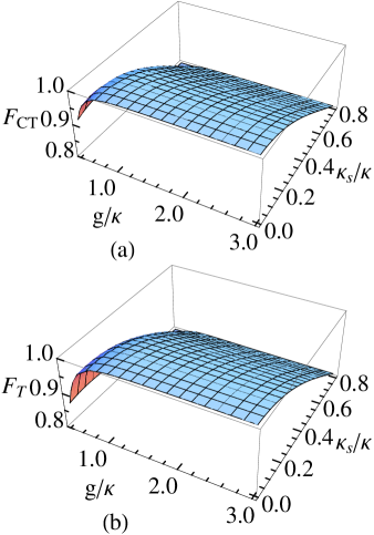
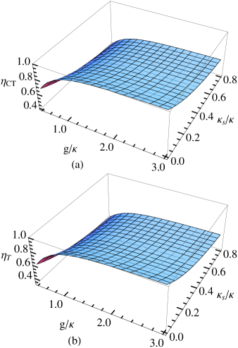
Fidelity and efficiency estimation. The average fidelities and the efficiencies of the present universal quantum gates as the function of the coupling strength and the side leakage rate are shown in Figs. 4 and 5, respectively. These results indicate that the fidelity and the efficiency behaviors of the two gates are similar to each other. When is very small and is large, the fidelities and the efficiencies of the gates are close to one. Both the fidelities and the efficiencies are high in both the strong coupling regime [] and the weak coupling regime [] when the ratio of the side leakage to the cavity decay is low. However, with an increase or a decrease , the fidelities and the efficiencies of the gates declines. Here the fidelities and the efficiencies of the single-qubit operations performed on the photons or the QDs in our schemes are unity, that is, the imperfect operation and the photon loss in the single-qubit operations are not taken into account. To get high fidelities and efficiencies of the gates, a small side leakage is required, and it can be achieved by improving the sample growth and optimizing etch processing observe2 . may be achieved for a pillar microcavity observe2 and reduce to by decreasing the reflection of the top mirror Hu1 . For a QD-cavity system, , , and have been observed in experiment observe1 ; observe2 ; Largesize . For our protocols, when and , and with and , respectively. If the cavity side leakage is negligible, the average fidelities of our quantum gates are close to one with a near-unity success probability (, , , when ). Here the subscripts and represent our CNOT gate and Toffoli gate, respectively.
The fidelities of aforementioned universal quantum gates are decreased by a amount of due to the exciton dephasing effect caused by the exciton decoherence Hu2 . That is, the fidelity depends on the coherence time and the cavity photon coherence time . Since the information of the polarization photon is transferred to the electron through the excitonic state, the exciton dephasing affects the state of the electron. The exciton dephasing only reduces the fidelity by a few percents due to the optical dephasing caused by population relaxation or the loss of phase coherence among the dipoles and the spin dephasing caused by spin interactions with the surrounding nuclei in self-assemble In(Ga)As-based QDs. The optical coherence time of excitons can be in several hundreds of picoseconds range at low temperature while the cavity photon lifetime is much shorter than the cavity photon lifetime 10 ps (: ) opticldeph1 ; opticldeph2 ; opticldeph3 . The coherence time of a QD-hole spin is longer than 100 ns Hole-QD and it is at least three orders of magnitude longer than the cavity photon lifetime ps, so it can be neglected. Besides the exciton dephasing, a few percent heavy-light hold mixing in the valence reduces the fidelity by a few percents opticselec . This effect can be reduced by improving the sample design and choosing different types of QDs.
References
- (1) Barenco, A. et al. Elementary gates for quantum computation. Phys. Rev. A 52, 3457–3467 (1995).
- (2) Gershenfeld, N. A. & Chuang, I. L. Bulk spin-resonance quantum computation. Science 275, 350–356 (1997).
- (3) Knill, E., Laflamme, R. & Milburn, G. J. A scheme for efficient quantum computation with linear optics. Nature 409, 46–52 (2001).
- (4) Feng, G., Xu, G. & Long, G. Experimental realization of nonadiabatic Holonomic quantum computation. Phys. Rev. Lett. 110, 190501 (2013).
- (5) Hua, M., Tao, M. J. & Deng, F. G. Universal quantum gates on microwave photons assisted by circuit quantum electrodynamics. Phys. Rev. A 90, 012328 (2014).
- (6) Vidal, G. & Dawson, C. M. Universal quantum circuit for two-qubit transformations with three controlled-NOT gates. Phys. Rev. A 69, 010301 (2004).
- (7) Vatan, F. & Williams, C. Optimal quantum circuits for general two-qubit gates. Phys. Rev. A 69, 032315 (2004).
- (8) Shende, V. V., Markov, I. L. & Bullock, S. S. Minimal universal two-qubit controlled-NOT-based circuits. Phys. Rev. A 69, 062321 (2004).
- (9) Shende, V. V., Bullock, S. S. & Markov, I. L. Recognizing small-circuit structure in two-qubit operators. Phys. Rev. A 70, 012310 (2004).
- (10) Nielsen, M. A. & Chuang, I. L. Quantum Computation and Quantum Information (Cambridge University Press, Cambridge, 2000).
- (11) Shi, Y. Y. Both Toffoli and controlled-not need little help to do universal quantum computation. Quant. Inf. Comput. 3, 084–092 (2003).
- (12) Shende, V. V. & Markov, I. L. On the CNOT-cost of Toffoli gate. Quant. Inf. Comput. 9, 0461–0468 (2009).
- (13) Loss, D. & DiVincenzo, D. P. Quantum computation with quantum dots. Phys. Rev. A 57, 120 (1998).
- (14) Petta, J. R. et al. Coherent manipulation of coupled electron spins in semiconductor quantum dots. Science 309, 2180–2184 (2005).
- (15) Greilich, A. D. et al. Mode locking of electron spin coherences in singly charged quantum dots. Science 313, 341–345 (2006).
- (16) Press, D. et al. Ultrafast optical spin echo in a single quantum dot. Nat. Photo. 4, 367–370 (2010).
- (17) Ciorga, M. et al. Addition spectrum of a lateral dot from Coulomb and spin-blockade spectroscopy. Phys. Rev. B 61, R16315(R) (2000).
- (18) Elzerman, J. M. et al. Few-electron quantum dot circuit with integrated charge read out. Phys. Rev. B 67, 161308(R) (2003).
- (19) Atatüre, M. et al. Quantum-dot spin-state preparation with near-unity fidelity. Science 312, 551–553 (2006).
- (20) Atatüre, M., Dreiser, J., Badolato, A. & Imamoglu, A. Observation of Faraday rotation from a single confined spin. Nat. Phys. 3, 101–106 (2007).
- (21) Hanson, R. et al. Single-shot readout of electron spin states in a quantum dot using spin-dependent tunnel rates. Phys. Rev. Lett. 94, 196802 (2005).
- (22) Berezovsky, J., Mikkelsen, M. H., Stoltz, N. G., Coldren, L. A. & Awschalom, D. D. Picosecond coherent optical manipulation of a single electron spin in a quantum dot. Science 320, 349–352 (2008).
- (23) Press, D., Ladd, T. D., Zhang, B. Y. & Yamamoto, Y. Complete quantum control of a single quantum dot spin using ultrafast optical pulses. Nature 456, 218–221 (2008).
- (24) Gupta, J. A., Knobel, R., Samarth, N. & Awschalom, D. D. Ultrafast manipulation of electron spin coherence. Science 292, 2458–2461 (2001).
- (25) Chen, P. C., Piermarocchi, C., Sham, L. J., Gammon, D. & Steel, D. G. Theory of quantum optical control of a single spin in a quantum dot. Phys. Rev. B 69, 075320 (2004).
- (26) Hu, C. Y., Young, A., O’Brien, J. L., Munro, W. J. & Rarity, J. G. Giant optical Faraday rotation induced by a single-electron spin in a quantum dot: Applications to entangling remote spins via a single photon. Phys. Rev. B 78, 085307 (2008).
- (27) Hu, C. Y., Munro, W. J., O’Brien, J. L. & Rarity, J. G. Proposed entanglement beam splitter using a quantum-dot spin in a double-sided optical microcavity. Phys. Rev. B 80, 205326 (2009).
- (28) Hu, C. Y., Munro, W. J. & Rarity, J. G. Deterministic photon entangler using a charged quantum dot inside a microcavity. Phys. Rev. B 78, 125318 (2008).
- (29) Hu, C. Y. & Rarity, J. G. Loss-resistant state teleportation and entanglement swapping using a quantum-dot spin in an optical microcavity. Phys. Rev. B 83, 115303 (2011).
- (30) Brunner, N., Young, A. B., Hu, C. Y. & Rarity, J. G. Proposal for a loophole-free Bell test based on spin-photon interactions in cavities. New J. Phys. 15, 105006 (2013).
- (31) Young, A. B., Hu, C. Y. & Rarity, J. G. Generating entanglement with low--factor microcavities. Phys. Rev. A 87, 012332 (2013).
- (32) Bonato, C. et al. CNOT and Bell-state analysis in the weak-coupling cavity QED regime. Phys. Rev. Lett. 104, 160503 (2010).
- (33) Wei, H. R. & Deng, F. G. Universal quantum gates for hybrid systems assisted by quantum dots inside double-sided optical microcavities. Phys. Rev. A 87, 022305 (2013).
- (34) Ren, B. C., Wei, H. R. & Deng, F. G. Deterministic photonic spatial-polarization hyper-controlled-not gate assisted by a quantum dot inside a one-side optical microcavity. Laser Phys. Lett. 10, 095202 (2013).
- (35) Ren, B. C. & Deng, F. G. Hyper-parallel photonic quantum computation with coupled quantum dots. Sci. Rep. 4, 4623 (2014).
- (36) Wei, H. R. & Deng, F. G. Scalable photonic quantum computing assisted by quantum-dot spin in double-sided optical microcavity. Opt. Express 21, 17671–17685 (2013).
- (37) Wang, C., Zhang, Y. & Jin, G. S. Entanglement purification and concentration of electron-spin entangled states using quantum-dot spins in optical microcavities. Phys. Rev. A 84, 032307 (2011).
- (38) Wang, T. J., Song, S. Y. & Long, G. L. Quantum repeater based on spatial entanglement of photons and quantum-dot spins in optical microcavities. Phys. Rev. A 85, 062311 (2012).
- (39) Ren, B. C., Wei, H. R., Hua, M., Li, T. & Deng, F. G. Complete hyperentangled-Bell-state analysis for photon systems assisted by quantum-dot spins in optical microcavities. Opt. Express 20, 24664–24677 (2012).
- (40) Wang, T. J., Lu, Y. & Long, G. L. Generation and complete analysis of the hyperentangled Bell state for photons assisted by quantum-dot spins in optical microcavities. Phys. Rev. A 86, 042337 (2012).
- (41) Warburton, R. J. et al. Charged excitons in self-assembled semiconductor quantum dots. Phys. Rev. Lett. 79, 5282 (1997).
- (42) Walls, D. F. & Milburn, G. J. Quantum Optics (Springer-Verlag, Berlin, 1994)
- (43) Reitzenstein, S. et al. AlAs/GaAs micropillar cavities with quality factors exceeding 150.000. Appl. Phys. Lett. 90, 251109 (2007).
- (44) Reithmaier, J. P. et al. Strong coupling in a single quantum dot-semiconductor microcavity system. Nature 432, 197–200 (2004).
- (45) Yoshie, T. et al. Vacuum Rabi splitting with a single quantum dot in a photonic crystal nanocavity. Nature 432, 200–203 (2004).
- (46) Peter, E. et al. Exciton-photon strong-coupling regime for a single quantum dot embedded in a microcavity. Phys. Rev. Lett. 95, 067401 (2005).
- (47) Loo, V. et al. Quantum dot-cavity strong-coupling regime measured through coherent reflection spectroscopy in a very high- micropillar. Appl. Phys. Lett. 97, 241110 (2010).
- (48) Romero, G., Ballester, D., Wang, Y. M., Scarani, V. & Solano, E. Ultrafast quantum gates in circuit QED. Phys. Rev. Lett. 108, 120501 (2012).
- (49) Stojanović, V. M., Fedorov, A., Wallraff, A. & Bruder, C. Quantum-control approach to realizing a Toffoli gate in circuit QED. Phys. Rev. B 85, 054504 (2012).
- (50) Zhou, Y., Zhang, G. F., Yang, F. H. & Feng, S. L. SWAP operation in the two-qubit Heisenberg model: Effects of anisotropy and magnetic field. Phys. Rev. A 75, 062304 (2007).
- (51) Heule, R., Bruder, C., Burgarth, D. & Stojanović, V. M. Local quantum control of Heisenberg spin chains. Phys. Rev. A 82, 052333 (2010).
- (52) Tanamoto, T., Becker, D., Stojanović, V. M. & Bruder, C. Preserving universal resources for one-way quantum computing. Phys. Rev. A 86, 032327 (2012).
- (53) Kimble, H. J. In Cavity Quantum Electrodynamics, (Academic, San Diego, 1994).
- (54) Bayer, M., et al. Fine structure of neutral and charged excitons in self-assembled In(Ga)As/(Al)GaAs quantum dots. Phys. Rev. B 65, 195315 (2002).
- (55) Finley, J. J. et al. Fine structure of charged and neutral excitons in InAs-Al 0.6 Ga0.4 As quantum dots. Phys. Rev. B 66, 66, 153316 (2002).
- (56) Borri, P. et al. Ultralong dephasing time in InGaAs quantum dots. Phys. Rev. Lett. 87, 157401 (2001).
- (57) Birkedal, D., Leosson, K. & Hvam, J. M. Long lived coherence in self-assembled quantum dots. Phys. Rev. Lett. 87, 227401 (2001).
- (58) Langbein, W. et al. Radiatively limited dephasing in InAs quantum dots. Phys. Rev. B 70, 033301 (2004).
- (59) Brunner, D. et al. A coherent single-hole spin in a semiconductor. Science 325, 70–72 (2009).
- (60) Bester, G., Nair, S. & Zunger, A. Pseudopotential calculation of the excitonic fine structure of million-atom self-assembled In1-xGaxAs/GaAs quantum dots. Phys. Rev. B 67, 161306(R) (2003).
Acknowledgments
This work is supported by the National Natural Science Foundation of China under Grant Nos. 11174039 and 11474026, and NECT-11-0031.
Authors contributions
H.R. and F.G. wrote the main manuscript text and prepared figures 1-3. H.R. prepared figures 4 and 5. F.G. supervised the whole project. Both authors reviewed the manuscript.
Additional information
Competing financial interests: The authors declare no competing financial interests.