Flow and Tilt-Induced Orientation of the Moving Vortex Lattice in Amorphous NbGe Superconducting Thin Films
Abstract
The orientation and deformation of moving vortex lattices in the flux-flow state have been investigated in amorphous superconducting NbGe thin films. Employing a mode-locking technique, we detect how moving lattices deform and their orientation changes as a magnetic field is tilted from normal to the film surface. For high tilt angles the lattice orientation is aligned parallely with the tilt direction. Meanwhile for low tilt angles the lattice orientation depends on the vortex velocity and a velocity-induced reorientation occurs. The characteristic velocity for the reorientation varies remarkably as the moving lattices deform. The observed features are consistent with an extended bond-fluctuation theory, revealing that the anisotropic shaking vortex motion is essential for determining the orientation of moving vortex lattices.
1 Introduction
Over the past few decades there has been considerable interest in the orientation of a hexagonal vortex lattice (VL) in type II superconductors [1]. Within the London approximation for isotropic superconductors all the possible orientations of the vortex lattice are degenerate in energy[2, 3], while this is lifted not simply by tilting an applied magnetic field [4, 5], but also when driven by applying a transport current. In experiments various imaging techniques such as Bitter decoration [6], small angled neutron scattering [7, 8] and scanning tunneling microscopy [9, 10, 11] have provided structural evidence for the hexagonal order in moving VLs, and some of them have shown that the lattice orientation (one of close-packed directions of the hexagonal VL) is aligned to be either parallel or perpendicular to the flow direction. These flow-induced orientations, including a reorientation between them, have been observed on both crystalline [6, 10] and non-crystalline weak pinning superconductors [12, 13, 14], and thus underlying crystallographic orientations are not at play. It is rather essential to understand how quenched disorder affects the orientation of moving VLs. Schmid and Hauger pointed out, for a long time ago, that the dissipation of the vortex motion is minimized when the lattice orientation is aligned parallely with the direction of its motion [15]. The parallel orientation has been supported by recent theoretical and numerical simulation studies [16, 17, 18] including the unique concept of the shaking temperature quantifying the effective influence of inhomogenous environment on moving vortices [19, 20, 21]. However, the other lattice orientation, the perpendicular orientation, has been shown in limited theoretical studies with different approaches [22, 23, 24]. Therefore, it needs a physical picture which describes fully the puzzling mechanism for those two orientations, including the reorientation of moving VLs.
The issue of the orientation of moving VLs would be interesting when the magnetic field is rotated from normal to the sample surface. Since the orientation of moving lattices should be aligned parallely with the tilt direction [3], one expects that the tilt-induced mechanism competes with the flow-induced one when tilt- and flow-induced orientations are different. In addition, for thin superconductors, the field inclination leads to the deformation of VLs in the sample surface frame [25]. Our principle interest is to what extent the lattice deformation (the anisotropy in VL parameters) could bear upon the reorientation of moving lattices. To address the issue, in this study, we present the flow- and tilt-induced (re)orientation of (deformed) moving vortex lattices observed on weak pinning, amorphous NbGe superconducting thin films by means of a mode-locking (ML) technique.
This manuscript is organized as follows: In Sec. 2 we describe sample preparation and characterizations, followed by our experimental setup for ML measurements. In Sec. 3 we present the experimental results of ML features and discuss the lattice orientation and the anisotropy in VL parameters obtained in different tilt directions. Derived consequences for dynamic phase diagrams of the lattice orientation are discussed and they are compared with an extended anisotropic bond-fluctuation theory [21, 26]. Finally, we summarize our findings in Sec. 4.
2. Experimental
Amorphous NbxGe1-x () superconducting thin films were deposited upon Si substrates by rf magnetron sputtering. We used a 3 inch diameter niobium target (purity 99.95) with germanium sheets (purity 99.999) on top and applied 70 W rf power to the target. The NbGe films with 0.28 m thick were structured into bridge patterns by using metal masks covering Si substrates. We used two bridge films of which geometry and material parameters are as follows: For the film 1 the width and length between voltage contacts are 0.10 mm and 4.00 mm, respectively; the superconducting transition temperature is 4.09 K, the slope of the second critical field against temperature near is 2.1 T/K, and the normal state resistivity is 1.44 m. Using the dirty-limit expression [27], the coherence length at K is 6.1 nm, the penetration depth at K is 0.62 m (), and the Ginzburg-Landau parameter is 62. For the film 2 mm, mm, 3.50 K, 2.0 T/K, 1.46 m, nm, 0.68 m and 68. Because of large , the vortex density is nearly equal to the applied magnetic field (i.e., ) when the field is applied perpendicularly to the film surface.
The NbGe thin films have weak pinning properties for vortices in magnetic fields and temperatures studied. The depinning current density determined from a current-voltage () curve with 1 V criterion is typically 10 - 100 A/cm2 at = 0.6 and = 0.4, which is of the order of for weak pinning, thin crystals of NbSe2 [28]. The pinning strength can be characterized by the transverse correlation length being roughly 10 times larger than the lattice spacing of the regular hexagonal VL, determined from two-dimensional collective pinning analysis [27, 29]. The curve exhibits the linear flux-flow behavior, of which flow resistivity was well discussed in Ref. 30.
We used a laboratory-built insert with a single-axis tilt stage. The film(s) and the tilt stage were immersed into pumped liquid 4He bath, of which vapor pressure was regulated by a throttle valve and a capacitance manometer. This allows us to precisely control the temperature of the bath from 4.2 K down to 2 K.
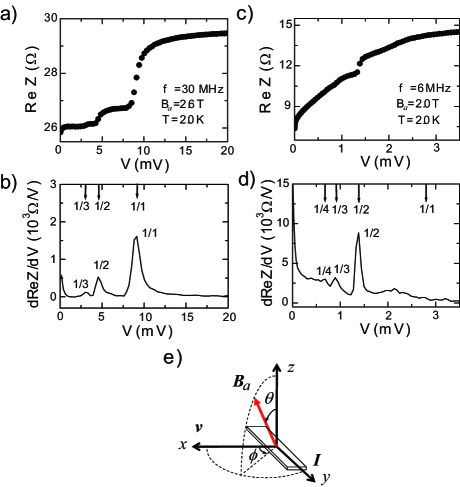
A sketch in Fig. 1e represents the orientation of the magnetic field with respect to the film lying on the plane (the tilt stage). The transport current is applied along the axis and vortices flow along the axis. is the tilt angle of the magnetic field from normal to the film surface (the axis), and is the in-plane angle between the flow direction (the axis) and the field projection onto the plane. In our experimental setup, was adjusted by rotating the tilt stage, and it was measured in situ with a Hall probe attached to the tilt stage (the plane). Due to the line tension of coaxial cables fixed onto the tilt stage, was varied within a limited range of 0∘ 70∘. By contrast, the direction of the tilt plane was adjusted by rotating the bridge film about the tilt axis of the stage before cooling, and two directions of 0∘ and 90∘ were studied in the present study.
The mode locking is based on dynamic resonance, which occurs when an internal frequency , characterizing the periodicity (velocity modulation) of moving lattices in the flow direction, is related harmonically to the frequency of an ac current superimposed on top of the transport (dc) current , i.e., , where is the average velocity and , are integers [31, 32, 33, 34, 35, 36, 37, 38]. This technique allows us detect not only the periodic vortex spacing along the flow direction, but also the deformation and orientation of moving VLs [12]. It has been shown that the large amplitude ac current () changes the orientation of moving lattices [39]. In order to avoid this effect, in this study, we employ the rf impedance technique which can detect the mode locking with the small amplitude ac current () [31, 13, 40]. For the technique we used an LCR meter (Agilent 4285A) with dc bias option (4285A -001), allowing rf impedance measurements up to 30 MHz after careful calibration for the coaxial cables. All the measurements were performed after cooling the films in zero magnetic field.
3. Results and Discussion
3.1 Moving vortex lattices in a perpendicular magnetic field
To provide the physical picture(s) of the mode locking for moving VLs, let us show some of ML results observed in the flux-flow state for the magnetic field applied perpendicularly to the sample surface (). During the ML experiments, we ramped up/down dc current, with superimposing the small, constant amplitude of ac current on top [40]: As responses, we measured both the flux-flow (dc) voltage and the real part of the complex rf impedance. To display how the complex impedance shows a ML feature(s), we plot against . The plot thus obtained in the film 1 is shown in Fig. 1a. One can see that exhibits multiple jumps, as observed in previous studies [31, 13]. The ML feature can be more clearly displayed by plotting the derivative of the curve in Fig. 1b, where multiple peaks of dd are visible. These can be identified with the fundamental ( 1/1) and subharmonics (1, 1) using the following arguments: the dd curve has three peaks with different height. Focusing on the corresponding voltages for the peaks, one can find that the voltage for the largest peak is nearly two (three) times larger than one for the second largest peak (the smallest peak). Consequently, we find that the largest peak corresponds to fundamental, and the second and third ones are subharmonics of 1/2 and 1/3, respectively. No harmonic with 2 appears because of the small amplitude ac current [41, 42]. Another curve is shown in Fig. 1c. The differential plot of the curve (Fig. 1d) shows clearly that the largest and second largest peaks correspond to 1/2 and 1/3 subharmonics, respectively. The smallest peak is 1/4 subharmonic, and the fundamental peak is not visible. Those two sets of the ML features with the fundamental largest peak (FLP) and 1/2 subharmonic largest peak (SLP) are typical for the present study.
The observed features originate from the hexagonal orientation of moving VLs. In previous studies made on amorphous MoGe films [12, 13, 14], we have shown that the lattice orientation is characterized by whether one of close-packed (CP) directions of the hexagonal VL is parallel or perpendicular to the flow direction. For the parallel orientation, as depicted in Fig. 1a in Ref. 12, the periodic lattice spacing in the flow direction is identified with the VL spacing, i.e., , indicating the internal frequency of the moving lattice to be . Since the vortex motion induces a voltage over the bridge film with length , the voltage condition for the mode locking is given by
| (1) |
We note that, in the present study, the harmonic number is always unity () because of the small ac current [42]. Assuming the lattice spacing for the regular hexagonal VL, i.e., with a magnetic flux quantum , we estimate the fundamental and subharmonic ML voltages and denote them by arrows in Fig. 1b. One can see that the arrows are quantitatively in good agreement with the peaks, including the identification of harmonic and subharmonic numbers . Thus, from the agreements we are convinced that the FLP feature of Figs. 1a and 1b corresponds to the parallel orientation of moving lattices. The similar argument identifies the SLP feature of Figs. 1c and 1d with the perpendicular orientation of moving lattices: As sketched in Fig. 1b in Ref. 12, the perpendicular orientation is characterized by the periodicity of the row spacing along the flow direction. Thus, the ML voltage for the perpendicular orientation is given by
| (2) |
Those multiple subharmonics and fundamental are important for identifying the lattice orientation, however the conclusion does not change as long as one of identified ML features is given. To make the argument simple, we focus on the ML voltage at the largest peak of the FLP (SLP) feature.
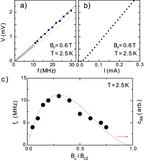
The lattice orientation observed above depends on the vortex velocity and a flow-induced reorientation occurs as the vortex velocity (frequency) increases. This behavior can be clearly seen by showing how the ML feature changes with frequency. Figure 2a shows the results obtained in the film 2 at 0.6 T and = 2.5 K. As depicted by open and solid square symbols, the SLP feature indicative of the perpendicular orientation appears in low frequencies, while the FLP one of the parallel orientation in high frequencies. Thus, from the ML features, one can immediately find that the flow-induced reorientation occurs at 11 MHz.
The same conclusion can be drawn from the magnitude of the ML voltage. As observed, for both features the corresponding voltage increases linearly with frequency, but there is difference in the slope related to the VL parameters. A solid line represents the ML voltage condition for the parallel orientation [Eq. (1) with ], while a dotted line does for the perpendicular orientation [Eq. (2) with ]. These are obtained simply by substituting the sample length and the magnetic field strength into Eqs. (1) and (2), without adjustable parameters. One can see that the former line agrees quantitatively with the higher frequency results and the latter line does the lower frequency ones. Thus, the reorientation of moving lattices is marked by a small jump of the ML voltage at the reorientation frequency 11 MHz.
Figure 2b shows the corresponding curve. It exhibits the linear flux-flow behavior and does not accompany any noticeable anomaly, indicating that no discontinuous change in the vortex velocity or the vortex density occurs at the reorientation. The corresponding reorientation velocity is m/s, which is two decades smaller than the critical velocity m/s for the flux-flow instability [43]. These results indicate that a proposed (reorientation) mechanism based on the relaxation of the order parameter [43, 44, 39] is not relevant to the observed reorientation.
Additional measurements of the reorientation made in different magnetic fields (vortex density) provide some insight into the mechanism for the reorientation. As plotted in Fig. 2c the reorientation frequency increases with the field and takes a maximum at . After that, it decreases with increasing the field. The broad peak behavior of is qualitatively in agreement with the field dependence of the shear elastic modulus of the regular VL represented by a solid curve [30, 45]. This qualitative coincidence suggests that the elastic response of moving lattices plays an important role upon the flow-induced reorientation.
3.2 Moving vortex lattices in an inclined magnetic field
To track further the physical origin for the reorientation, we study how the field rotation distorts the moving lattice and also how this influences on the two orientations induced by the vortex flow. Since the London theory implies that the orientation of deformed lattices should be aligned parallely with the tilt direction, the tilt-induced mechanism competes with the flow-induced one when the tilt- and flow- induced orientations are different. In this section, we focus on the ML results observed in two tilt directions of and , and present how the flow-induced orientation changes into the tilt-induced one as function of tilt angle .
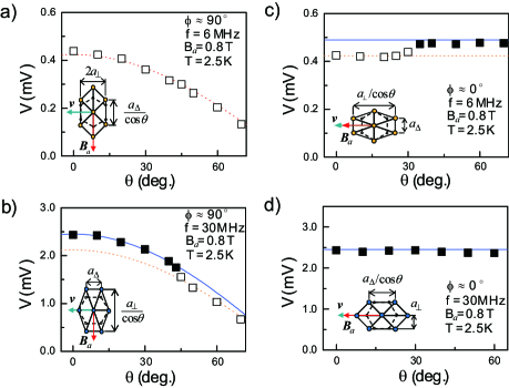
Figure 3a shows the tilt dependence of the ML voltage observed in the tilt direction of . As denoted by open symbols, the SLP feature, indicative of the perpendicular orientation, is observed for all the tilt angles studied. This is consistent with the tilt-induced picture where one of CP directions of the hexagonal VL should be aligned parallely with the tilt direction [3]. The corresponding ML voltage decreases with increasing , and this reduction is consistent with the dotted curve representing the ML voltage condition for :
| (3) |
Here, we assume that the vortex density varies as and the lattice parameter along the flow direction remains unchanged (Consequently, the lattice parameter along the tilt direction is stretched by as illustrated in the inset to Fig. 3a). We note that the results were taken at 6 MHz () and the flow-induced orientation (at ) is the perpendicular one. Thus, the flow- and tilt-induced orientation coincide, and the perpendicular orientation appears irrespective of .
The situation is different at high frequencies . The flow-induced, parallel orientation appears at and it should switch to the tilt-induced, perpendicular orientation by rotating the field. This is clearly observed in Fig. 3b, where the ML results taken at 30 MHz () are plotted. As observed, the FLP feature (the solid symbol) changes into the SLP one (the open symbol) as increases, and it occurs at . In other words, the parallel orientation persists up to . This is against the above picture based on the London theory that the lattice orientation should be aligned parallely with the tilt direction at any non-zero tilt angle [3]. The corresponding ML voltages reveal how the moving lattices deform with increasing . The ML condition for the parallel orientation is given as
| (4) |
This is simply times larger than the perpendicular condition in Eq. (3) since for the regular VL. As shown in Fig. 3b, the solid curve representing the parallel condition explains well the results until a step like drop at the reorientation angle. This quantitative agreement evidences that the moving lattices are expanded along the tilt direction. Thus, in the range of the deformation and orientation of moving lattices do not coincide in direction as illustrated in the inset to Fig. 3b.
The discrepancy between the deformation and orientation of moving lattices also occurs in the other tilt direction of the magnetic field, i.e., . Since the flow direction coincides with the tilt direction, one can expect that the deformation and orientation of moving lattices are aligned parallely with the flow (and tilt) direction as illustrated in the inset to Fig. 3d. However, the ML features taken at the low frequency (6 MHz) reveal the presence of the perpendicular orientation at nonzero tilt angles. As shown in Fig. 3c, the perpendicular orientation persists up to , above which the parallel orientation appears. Thus, in the range of the orientation of moving lattices is not aligned parallely with the flow (and tilt) direction. The lattice deformation can be found from the tilt dependence of the corresponding ML voltage. As represented by solid and dotted lines in Fig. 3c, for both orientations the ML voltage condition is independent of , since the expansion of the lattice parameter along the flow (and tilt) direction by (see the inset) is canceled with the reduction of the vortex density . As observed, the results follow nicely the perpendicular condition (the dotted line) until , above which they do the parallel condition (the solid line). Thus, the moving lattices deform in the flow (and tilt) direction indeed, but their orientation is not aligned parallely with the direction at low tilt angles (see the inset). Since the perpendicular orientation appears at , the discrepancy originates from the fact that the flow-induced orientation, being different from the tilt-induced one, survives at low tilt angles. This is not noticeable in the high frequency (30 MHz) results given in Fig. 3d where the parallel orientation appears for all the tilt angles, since the flow-induced orientation coincides with the tilt-induced one.
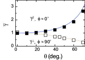
Let us discuss the anisotropy of VL parameters with respect to the flow direction: We define the anisotropy as the ratio of the lattice parameter along the flow direction divided by one perpendicular to the flow direction. Taking the perpendicular orientation of moving lattices, for instance, we obtain . For the parallel orientation it needs simply to replace with , i.e., . The anisotropy thus obtained from the results in Figs. 3a ( and 6 MHz) and 3d ( and 30 MHz) is summarized in Fig. 4. For clarity we normalize the results by the ratio of the VL parameters of the regular VL at , i.e., and . One finds that varies approximately as represented by a dotted curve. This agrees with the picture that the moving lattices are stretched perpendicularly to the flow direction as discussed above (see the inset to Fig. 3a). Meanwhile, increases as (represented by a solid curve) with increasing , being consistent with the picture of the lattice expansion along the flow direction (see the inset to Fig. 3d). These agreements give a further support for the description of lattice deformations illustrated in Fig. 3.
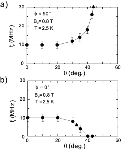
The above findings related to the lattice orientation imply that the tilt-induced reorientation occurs, but it depends on not only the tilt direction , but also the vortex velocity (frequency). To give further insight into the reorientation of moving lattices, it is useful to trace how the reorientation frequency varies with . To obtain this trace, for each tilt angle , we measured the frequency dependence of the mode locking, and determined the reorientation frequency (see Fig. 2a). The results thus obtained in the tilt direction of are given in Fig. 5a. As the field is rotated, the reorientation frequency exhibits a rapid increase with downward curvature and it reaches the maximum frequency of 30 MHz at . Since separates the parallel orientation from the perpendicular orientation of moving lattices, the results can be viewed as the dynamic phase diagram for the lattice orientation: Namely, the region of the parallel orientation lies above the curve, while that of the perpendicular orientation appears below the curve. In other words, for high tilt angles , the tilt-induced perpendicular orientation appears irrespective of the vortex velocity. For low tilt angles the lattice orientation depends on the vortex velocity and the flow-induced reorientation occurs. The corresponding reorientation velocity increases as the lattice deformation becomes larger (the anisotropy becomes smaller). Different results are obtained in the tilt direction of where the moving lattices are stretched in the flow direction. As shown in Fig. 5b, decreases with increasing and it seems to vanish at . Namely, for low tilt angles the more stretched the moving lattices are, the smaller the reorientation frequency becomes. As a result, the region of the perpendicular orientation shrinks and the tilt-induced parallel orientation dominates high tilt angles . From these results we remark that (1) for high tilt angles () the field inclination determines the orientation of moving VLs: (2) For low tilt angles () the vortex velocity determines the lattice orientation: (3) The corresponding reorientation velocity varies sensitively as the moving lattices deform and it increases (decreases) as the anisotropy becomes small (large).
The argument of the London theory indicates that the orientation of the vortex lattice should be aligned parallelly with the tilt direction as soon as the magnetic field is tilted from normal to the film surface [3]. This picture disagrees with our experimental findings for low tilt angles (). Therefore a factor(s) other than the vortex-vortex interaction should be relevant to the observed lattice orientations. Since the vortices are driven over the disordered (pinning) environment, let us discuss the above results from the viewpoint of the anisotropic shaking motion of moving lattices. Scheidl and Vinokur (SV) have introduced pinning-bond widths characterizing the relative displacements of two neighboring vortices and have argued that the anisotropy in the bond widths could determine the orientation of moving lattices [21]. When the bonds along the flow direction (-bonds) fluctuate weakly than those perpendicular to the flow (-bonds), the moving vortices are aligned parallelly with the flow direction. This results in the parallel orientation of moving lattices. In opposite case, the vortices should be aligned perpendicularly to the flow direction, resulting in the perpendicular orientation of moving lattices [26]. The dependences of - () and -bond widths () on the vortex velocity are given in limited cases [21]: For small velocities the elastic interaction dominates and both bond widths diverge as at 0. However, prefactors show that the -bond width is larger than the -bond width. Thus their ratio is more than 1 and the perpendicular orientation is favorable at small velocities [26]. As the velocity increases, the width of bonds decreases as , which is faster than the bond width , indicating the parallel orientation ( 1) at large velocities. Thus, the reorientation marks the point where the widths of and bonds become comparable, i.e., 1. We expect that this condition depends how the moving lattices deform and is scaled with the anisotropy of the lattice parameters of moving lattices, i.e., . For the condition gives . Namely, the -bond width is smaller than the -bond width, and this requires that the reorientation velocity is faster than one for no deformation at the perpendicular field (). This is consistent with our observation that increases with (see Fig. 5a). For the condition reads . Namely, the -bond width is larger than the -bond width, and thus the reorientation velocity becomes slower. This explains qualitatively the reduction of as increases (see Fig. 5b). A quantitative comparison can be made at the small velocity limit. According to the SV theory, the anisotropy of the bond widths is given as . Using 0.80 T and the coherence length 6.9 nm for the film 2, we obtain 1.3. This is quantitatively consistent with the lattice expansion at at which vanishes ( 0). These agreements suggest strongly that the anisotropic shaking motion plays an essential role for determining the orientation of moving VLs.
A further test of the SV model can be made on confined vortex systems such as narrow constrictions [41, 46, 47, 48, 49, 50] or possibly small disks [51, 52]. The shear rigidity of moving lattices appears in the transport properties such as the flux-flow resistance, and the anisotropy in VL parameters can be tuned by the matching condition between the vortex density and the size of the constriction. These would allow systematic and quantitative investigation on how the reorientation frequency varies with the anisotropy of VL parameters in confined moving lattices.
4. Summary
In summary, we have presented ML experiments of moving VLs in amorphous NbGe superconducting films. The rf ML technique allows us to find the orientation of moving lattices as function of frequency (the vortex velocity). The flow-induced reorientation of moving lattices occurs at the characteristic frequency , separating the perpendicular orientation at small velocities from the parallel orientation at large velocities. The magnetic field dependence of resembles qualitatively with that of the shear elastic modulus of the regular VL, suggesting the relevance of the elasticity of moving lattices on the reorientation.
Introducing the deformation of moving lattices by rotating the field in different directions, we have shown how the lattice orientation varies with tilt angle. The moving lattice is expanded in the direction of its motion when the field is rotated along the flow direction (), while for the field rotated perpendicularly to the flow direction () the moving lattices are stretched perpendicularly to the flow. For high tilt angles the orientation of moving lattices is aligned parallely with the tilt direction, being consistent with the London theory. Meanwhile for low tilt angles the lattice orientation depends on the vortex velocity and the flow-induced reorientation occurs. Focusing on the results for low tilt angles, we have traced how the reorientation frequency varies with tilt angle. The flow-induced reorientation needs large moving velocities when the moving lattices are stretched perpendicularly to the flow direction, while it occurs at small velocities when the lattices are expanded in the flow direction. Thus, the anisotropy in VL parameters is crucial for the flow-induced reorientation. The observed features are consistent with the extended picture of the anisotropic bond fluctuation theory. This reveals that the anisotropic shaking motion is the essential mechanism which governs the orientation of moving VLs.
N. K. thanks P. H. Kes, V. M. Vinokur, M. R. Eskildsen, T. Nishizaki and S. Okuma for stimulating discussions. This work was supported partly by the grant in Aid for Scientific research from MEXT (the Ministry of Education, Culture, Sports, Science and Technology), Japan.
References
- [1] K. Takanaka: Prog. Theor. Phys. 46 (1971) 1901.
- [2] L. J. Campbell, M. M. Doria, V. G. Kogan: Phys. Rev. B 38 2439 (1988).
- [3] V. G. Kogan, L. N. Bulaevskii, P. Miranovi and L. Dobrosavljevi-Gruji: Phys. Rev. B 51 15344 (1995).
- [4] C. A. Bolle, F. De La Cruz,P. L. Gammel, J. V. Waszczak, and D. J. Bishop: Phys. Rev. Lett. 71 (1993) 4039.
- [5] H.F. Hess, C. A. Murray, and J. V. Waszczak: Phys. Rev. B 50 (1994) 16528.
- [6] F. Pardo, F. de la Cruz, P. L. Gammel, E. Bucher and D. J. Bishop: Nature 396 (1998) 348.
- [7] U. Yaron, P. L. Gammel, D. A. Huse, R. N. Kleiman, C. S. Oglesby, E. Bucher, B. Batlogg, D. J. Bishop, K. Mortensen and K. N. Clausen: Nature 376 (1995) 753.
- [8] M. R. Eskildsen: Front. Phys. 6 (2011) 398.
- [9] A. M. Troyanovski, J. Aarts, and P. H. Kes: Nature (London) 399 (1999) 665.
- [10] A. Kohen, T. Cren, Th. Proslier, Y. Noat, W. Sacks, D. Roditchev, F. Giubileo, F. Bobba, A. M. Cucolo, N. Zhigadlo, S. M. Kazakov, and J. Karpinski: Appl. Phys. Lett. 86 (2005) 212503.
- [11] P. H. Kes (private communication)
- [12] N. Kokubo, B. Shinozaki and P. H. Kes: Physica C 468 (2008) 581.
- [13] N. Kokubo, T. Nishizaki, B. Shinozaki and P. H. Kes: Physica C 470 (2010) 43.
- [14] S. Okuma, Y. Yamazaki and N. Kokubo: Phys. Rev. B 80 (2009) 220501.
- [15] A. Schmid and W. Hauger: J. Low. Temp. Phys. 11 (1973) 667.
- [16] P. Le Doussal and T. Giamarchi: Phys. Rev. B 57 (1998) 11356.
- [17] L. Balents, M. C. Marchetti, and L. Radzihovsky: Phys. Rev. B 57 (1998) 7705.
- [18] C. J. Olson, C. Reichhardt, and F. Nori: Phys. Rev. Lett. 81 (1998) 3757.
- [19] A. E. Koshelev and V. M. Vinokur: Phys. Rev. Lett. 73 (1994) 3580.
- [20] A. B. Kolton, R. Exartier, L. F. Cugliandolo, D. Dominguez, and N. Gronbech-Jensen: Phys. Rev. Lett. 89 (2002) 227001.
- [21] S. Scheidl and V. M. Vinokur: Phys. Rev. B 57 (1998) 13800.
- [22] S. O. Valenzuela: Phys. Rev. Lett. 88 (2002) 247003.
- [23] N. Nakai, N. Hayashi, M. Machida: Physica C 469 (2009) 1106.
- [24] D. Li, A. M. Malkin and B. Rosenstein: Phys. Rev. B 70 (2004) 214529.
- [25] E. H. Brandt: Phys. Rev. B 48 (1993) 6699.
- [26] We note that the possibility of the perpendicular orientation at small velocities is not claimed in Ref. 21, although the analytical results of bond widths at the small velocity limit (-bond width is larger than -bond width) are derived.
- [27] P. H. Kes and C. C. Tsuei: Phys. Rev. B 28 (1983) 5126.
- [28] N. Kokubo, K. Kadowaki and K. Takita: Phys. Rev. Lett. 95 (2005) 177005.
- [29] A. I. Larkin and Yu. N. Ovchinnikov: J. Low Temp. Phys. 34 (1979) 409.
- [30] P. Berghuis, and P. H. Kes: Phys. Rev. B 47 (1993) 262.
- [31] A. T. Fiory: Phys. Rev. B 7 (1973) 1881.
- [32] P. Martinoli, L. Pardi, C. Pinzino, S. Santucci: Solid State Commun. 17 (1975) 207.
- [33] S. Bhattacharya, M. J. Higgins, and J. P. Stokes: Phys. Rev. B 38 (1988) 7177.
- [34] T. Takayama and L. Rinderer: J. Low. Temp. Phys. 75 (1989) 15.
- [35] A. Maeda, Y. Togawa, H. Kitano: Physica C 369 (2002) 177.
- [36] T. Kawaguchi and H. Matsukawa: Materials Science and Engineering: A 423 (2006) 204.
- [37] A. Harada, K. Enomoto, Y. Takahide, M. Kimata, T. Yakabe, K. Kodama, H. Satsukawa, N. Kurita, S. Tsuchiya, T. Terashima, and S. Uji : Phys. Rev. Lett. 107 (2011) 077002.
- [38] C. Reichhardt, R. T. Scalettar, and G. T. Zimanyi: Phys. Rev. B 61 (2000) R11914.
- [39] S. Okuma, D. Shimamoto and N. Kokubo: Phys. Rev. B 85 (2012) 064508.
- [40] The magnitude of the superimposed ac current was 7 A ( 20 A). Meanwhile, the dc current was ramped up to 1 mA in order to observe the ML feature in the flux-flow state.
- [41] N. Kokubo, R. Besseling, V. M. Vinokur and P. H. Kes: Phys. Rev. Lett. 88 (2002) 247004.
- [42] N. Kokubo, R. Besseling and P. H. Kes: Phys. Rev. B 69 (2004) 064504.
- [43] M. Liang and M. N. Kunchur: Phys. Rev. B 82 (2010) 144517.
- [44] D. Y. Vodolazov and F. M. Peeters: Phys. Rev. B 76 (2007) 014521.
- [45] E. H. Brandt: Phys. Rev. B 34 (1986) 6514.
- [46] A. Jukna, I. Barboy, G. Jung, A. Abrutis, X. Li, D. Wang, and Roman Sobolewski: J. Appl. Phys. 99 (2006) 113902.
- [47] V. Vlasko-Vlasov, U. Welp, G. Karapetrov, V. Novosad, D. Rosenmann, M. Iavarone, A. Belkin, and W.-K. Kwok: Phys. Rev. B 77 (2008) 134518.
- [48] A. V. Silhanek, J. Van de Vondel, A. Leo1, G. W. Ataklti, W. Gillijns and V. V. Moshchalkov: Supercond. Sci. Technol. 22 (2009) 034002.
- [49] K. Yu, M. B. S. Hesselberth, P. H. Kes, and B. L. T. Plourde: Phys. Rev. B 81 (2010) 184503.
- [50] R. Wordenweber, E. Hollmann, J. Schubert, R. Kutzner, G. Panaitov: Physica C 479 (2012) 69.
- [51] D. Lopez, W. K. Kwok, H. Safar, R. J. Olsson, A. M. Petrean, L. Paulius and G. W. Crabtree: Phys. Rev. B 82 (1999) 1277.
- [52] N. S. Lin, V. R. Misko, and F. M. Peeters: Phys. Rev. Lett. 102 (2009) 197003.