Dynamics of domain-wall Dirac fermions on a topological insulator: a chiral fermion beam splitter
Abstract
The intersection of two ferromagnetic domain walls placed on the surface of topological insulators provides a one-way beam splitter for domain-wall Dirac fermions. Based on an analytic expression for a static two-soliton magnetic texture we perform a systematic numerical study of the propagation of Dirac wave packets along such intersections. A single-cone staggered-grid finite difference lattice scheme is employed in the numerical analysis. It is shown that the angle of intersection plays a decisive role in determining the splitting ratio of the fermion beam. For a non-rectangular intersection, the width and, to a lesser extent, the type of domain walls, e.g. Bloch or Néel, determine the properties of the splitter. As the ratio between domain-wall width and transverse localization length of the Dirac fermion is increased its propagation behavior changes from quantum-mechanical (wave-like) to classical ballistic (particle-like). An electric gate placed near the intersection offers a dynamic external control knob for adjusting the splitting ratio.
pacs:
73.43.-f, 85.75.-d, 03.65.Pm, 02.30.JrI Introduction
There has been considerable progress in the investigation of Dirac fermions on (textured) TI surfaces in external electromagnetic fields. Experimentally, the Dirac cone spectrum with and without external magnetic field has been verified in recent experiments.analytis ; chen1 ; xia Position control of the Fermi energy within the bulk gap of the insulator has become feasible.chen2 ; checkelsky ; xiu ; kim ; wang ; ren Magnetic texturing of TI surfaces has been explored experimentally.chen1 ; honolka ; wei In one study using iron as the dopant, however, the easy axis has been reported to be in plane.honolka In thin films of MBE grown Cr doped ternary (BixSb1-x)2Te3 ferromagnetic order has been reported.chang With the theoretically predicted existence of topologically protected surface states confirmed in experiment, one of the next steps is to learn to manipulate them by structural design and to utilize their properties in chiral fermion devices. On the theoretical side, numerous papers have been published on related topics, such as magneto-transport on TI surfaces in presence of ferromagnetic layers, yokoyama ; soodchomshom ; yuan ; kong ; suwanvar ; wu spin-polarized magnetic impurities on TI surfaces and Landau levels,misawa ; vazifeh ; schwab ; nomura ; burkov the interaction of magnetic domain walls with Dirac fermions,loss ; chui ; castro lensing effects and transport perpendicular to domain walls,hassler ; wickles crossover from weak anti-localization to weak localization,liu2 and gate control of TI channel states.yokoyama2 An interferometer for chiral fermions has been proposed recently.hammerAPL
Surfaces of 3D topological insulators can be interpreted as a 2D domain wall between a spin-orbit driven band inversion within the insulator and normal band ordering in vacuum.qi ; fu ; moore ; zhang The topologically protected gapless surface states in form of helical-state Dirac cones can be manipulated further by time-reversal-symmetry-breaking (TRB) perturbations applied to the surface.qi ; hasan ; liu Indeed, it has been known for quite a while that an effective-mass inversion domain wall can produce a 1D chiral edge eigenstate for a 2D Dirac fermion Hamiltonian.jackiw Such edge states are required to observe a quantized Hall effect. TRB can be induced by exposure to an (effective) external magnetic field. For example, a ferromagnetic tip or permanent magnetic texture arising from the proximity of ferromagnets, in conjunction with magnetic doping of the surface, may be used to induce sign changes in the mass term of the effective Dirac equation.zhang ; honolka ; wei ; liu ; chen1 The expected order-of-magnitude for the mass-gap in materials, such as Bi2Se3, is up to several tens of meV.chen1 ; luo
Nanostructuring of TIs enhances the surface over the bulk contributions to fermion charge transport and provides another promising means to produce edge states, following strategies previously applied to graphene. It should be recalled that the properties of the surface states are a consequence of the TI bulk properties. Bulk doping can be used to manipulate surface state behavior.wray:2011 ; xiu:2011 ; beidenkopf:2011 ; zhang:2012 Compositional tuning of Dirac fermion electronic structure has been demonstrated for BiTl(S1xSed)2, Bi2(Te3-xSex). xu-2011 ; chen:2013 Placed on a substrate, electric contacts have been made to the TI.xiu:2011 ; chang:2013 Metal-TI junctions have been studied theoretically.modak:2012 Such structuring can be expected to lead to the realization of interesting quantum interference effects due to the helical nature of surface states, implying spin-polarized electric currents, the absence of back scattering, and robustness to moderate disorder. This strategy has lead to the experimental observation of the quantum anomalous Hall effect in a magnetic topological insulator.chang:2013 Quantum oscillations in TI nanoribbons in conjunction with high surface conductance (e.g., for Bi2Te3) have been investigated theoretically and in experiment.peng:2010 ; ihn:2010 ; xiu:2011
In this paper the dynamic properties of chiral fermions in channel states introduced by magnetic texturing of the surface of a TI insulator are explored. We perform a theoretical study of the propagation of chiral domain-wall fermions along the intersection of two ferro-magnetic domain walls imprinted upon the surface of a TI. In a systematic numerical analysis, we extract the one-way beam splitting properties regarding magnetic texturing, such as the angle of intersection, domain-wall thickness, and details of in-plane magnetization. Our time-dependent analysis is based on a newly developed scheme for a numerical treatment of the (2+1)D Dirac equation in presence of electromagnetic fields, whose numerical mathematical properties will be presented in a forthcoming publication. Here, the analysis is performed using static solitonic domain-wall crossings, valid in the adiabatic regime. The paper is organized as follows. In Sect. II we give a brief summary of chiral (domain wall) fermions in external electromagnetic fields, as relevant for TI surfaces and introduce 2-soliton magnetic textures. In Sect. II.3 we give the model Hamiltonian for our numerical analysis. Sect. III gives a summary of our single-cone numerical lattice model for (2+1) Dirac fermions. Sect. IV features some of our numerical results for chiral fermion beam splitters. Finally, a general summary and our conclusions are given in Sect. V.
II Chiral domain-wall fermions
II.1 Basic considerations
An effective (2+1)D model for the dynamics of Dirac fermions on a magnetically textured TI surface may be founded upon a Hamiltonian
| (1) |
consisting of the fermion Hamiltonian , the impurity Hamiltonian , and the interaction . For, the Dirac fermions in an external electromagnetic field one may write
| (2) |
Here, in the spin-orbit term denotes the kinetic momentum in presence of a vector potential associated with the external magnetic field , is the scalar potential energy, and and in the Pauli term are, respectively, the electron Bohr magneton and the Landé factor. The Pauli vector is proportional to the physical fermion spin with its direction-locked perpendicular to the particle current density and the normal vector to the surface .qi Note, that the simple form of the spin-orbit term can be extended to more precisely represent the energy dispersion away from the Dirac point, such as an account of hexagonal warping.qi ; alpichshev
The impurity spins may be modeled by a generic Heisenberg-type Hamiltonian of the form
| (3) |
and the Dirac fermion-impurity interaction by
| (4) |
Here and denote, respectively, the impurity spin and external magnetic field, for impurity site . Note that one must differentiate between the ”external” magnetic field experienced by fermions and impurities.
The physical situation envisioned and captured by the Hamiltonian is that of a TI surface which is densely covered by magnetic impurities which interact with one another, as well as with the Dirac fermions under an exchange interaction. Several possible origins for an exchange interaction have been discussed in the literature.rosenberg ; luo An external magnetic field may be applied to imprint and stabilize domain-wall formation between ferromagnetic ordered domains.
Subjecting to a mean-field approximation one obtains , where the effective magnetic field at impurity site is given as
| (5) |
The three contributions arise from the external magnetic field (including contributions from the orbital motion of Dirac fermions), impurity magnetization, and fermion spin polarization. The latter gives rise to a spin-transfer torque.
Similarly for the fermions,
where the effective magnetic field in the Pauli term is given by
| (7) |
and the vector potential entering the canonical momentum in the spin-orbit term contains the contribution from the external magnetic field and the magnetization of the impurities, as will be discussed below, such that .
In what follows we concentrate on the Dirac fermion dynamics. The impurity dynamics, in principle, can be treated self-consistently in parallel. However, it is generally accepted that the latter occurs on a time-scale which is long compared to the fermion dynamics and adiabatic schemes have been used successfully to model the interplay between the two subsystems.wenin
According to Eq. (II.1) the presence of magnetic impurities and a stabilizing external -field has two consequences for the dynamics of Dirac fermions: an impurity spin polarization (magnetization) M modifies the net external magnetic field from to and, for , introduces an exchange term (”mass term”), in addition to the Zeeman term, in Eqs. (II.1) and (2) below. Such a mass term has been estimated to be of the order of up to several tens of meV and represents the dominant magnetic-field contribution.luo For a fermion g-factor the effective magnetic exchange field required for a mass gap of meV is about 10 T.liu ; lande Such a magnetic exchange field will, as usual for ferromagnets, dominate any typical static external field T in Eq. (7) in the Pauli term of Eq. (II.1).
In order to estimate the magnetization M associated with an exchange field of 10 T, we use parameters typical for Mn impurities.vanesch Within the simple form and meV nm2 one needs an impurity density of about 0.1 nm-2 to achieve a mass gap of meV. Using , the magnetization per area is of the order of meV/(Gauss nm2). Based on this estimate and a layer thickness of 1 nm, the order of magnitude of the magnetization contribution to , , is about T, making this effect negligible in both the spin-orbit and Pauli term of Eq. (II.1). In principle there also is a topological field contribution due to the magneto-electric effect, but it is extremely small in magnitude ().qi ; garate In summary, the dominant magnetic-field effect onto the Dirac fermions arises from the exchange field, followed in importance by the external magnetic field in the spin-orbit term. The effect of an external magnetic field on the spectrum of TI Dirac fermions has been investigated both theoretically and experimentally (see Introduction I). It has a negligible effect on the dynamics of domain-wall Dirac fermions when compared to the in-plane component of the exchange term, as we have verified numerically in our studies detailed below. We conclude that the formation of domain-wall states and the dynamics of domain-wall Dirac fermions is dictated predominantly by the magnetic domain-wall structure (exchange field) and the external electric bias. However, the presence of an external magnetic field may be essential to pin domain walls and to imprint and stabilize a specific ferromagnetic domain-wall structure.
II.2 Solitonic magnetic textures
The rich physics of ferromagnetic domain wall dynamics has been well documented in the literature.how ; yokoyama:2010 ; loss ; chui ; castro Here we consider well-pinned hard ferromagnetic textures and explore domain-wall fermion dynamics on a time-scale which allows for a quasi-static treatment of the domain wall structure, neglecting spin-transfer torque effects.wenin The latter implies the regime of low current density. Our numerical approach can handle time-dependent magnetic domains, however, such an analysis will be the topic of future investigations.
An analytic model for stable, local-minima, 2D magnetic textures can be derived from solutions to a simple free energy functional which consists of an isotropic exchange term and an anisotropy term with as the easy axis. In terms of the unit magnetization and with it is
| (8) |
In spherical coordinates and takes the simple form
| (9) | |||||
Optimality conditions lead to and
| (10) |
Setting and rescaling one obtains the sine-Gordon equation (in ”imaginary time” )
Multi-soliton solutions are most directly found using Hirota’s bilinear expansion in .hirota ; bowtell ; zarkharov The single-soliton solution takes the form
| (11) |
This solution represents a magnetization domain wall along at .
A magnetic domain-wall intersection which represents a local minimum to the free energy functional Eq. (8) can be constructed from the two-soliton solution
| (12) |
We place the point of intersection at the coordinate origin, setting , retaining and to characterize the type of intersection. With suitable magnetic impurities present at or near the surface of the TI, such a ferromagnetic domain wall intersection may be induced by an array of magnetic poles of the form facing the TI surface.

II.3 The model Hamiltonian and domain-wall states
According to Sect. II the effective Hamiltonian for a single Dirac cone on the surface of the TI interacting with magnetic texture may be writtenqi ; zhang ; shan
| (13) |
According to Eq. (II.1) second and third term on the r.h.s., respectively, account for the presence of the magnetic texturing , with denoting the effective exchange coupling tensor, and an external scalar electric potential arising, for example, from a gate bias.
This effective Hamiltonian describes the 2D excitation spectrum near the Dirac point, including 1D edge states in presence of domain walls. Domain-wall edge states are responsible for an integer quantum Hall effect on the TI surface, as discussed in the literature.qi ; zhang For Eq. (13) and a single-soliton domain wall Eq. (11), with and , a domain-wall eigenstate exists which takes the simple formhasan
| (14) |
when neglecting in-plane contributions to the magnetization (valid when sufficiently far away from the domain wall).hammerAPL It features a linear dispersion , with the upper sign for and , and the lower sign for and . Note that a constant potential in Eq.(2) simply adds to the eigenvalue . Parallel and curved zero-mass lines have also been studied in the literature.tudorovskiy:2012 For a general form of an in-plane magnetization or other more complicated domain-wall structures eigenfunctions are best found numerically.
More complex magnetic texturing, where islands of positive mass neighbor islands of negative mass, produces a network of one-way chiral channel states.hammerAPL Here we study an elementary building block of such a network in form of an intersection of two linear domain walls.
With the realization of such a texture a reflection-less beam splitter for chiral fermions is established. This is demonstrated numerically below for the two-soliton texture Eq. (12).
III Numerical method: a single-cone lattice model
The time-dependent Dirac equation is solved numerically for in Eq. (2).
Putting the (single cone) Dirac equation onto a grid for numerical solution traditionally has been hampered by fermion doubling, that is, the lattice model has more eigenmodes than the original continuum model. Two different numerical finite difference schemes have been employed and compared in the course of this analysis. Both use a staggering of the spinor components in space and time. The first one has the following advantageous features:submCPC (i) it provides the exact (linear) dispersion relation for mass-less free Dirac fermions along the main axes and , (ii) it allows an implementation of absorbing boundary conditions via an imaginary potential term, and (iii) it allows for a removal of the second Dirac cone, located at the corners of the Brillouin zone, by a Wilson term.wilson The second one, briefly outlined below, avoids the fermion doubling problem altogether at the cost of loosing the
perfect (i.e., linear) dispersion property along the main coordinate axes for mass zero.nielsen It features a single Dirac cone dispersion without the need for using a Wilson mass term to get rid of the doublers. For simple rectangular magnetic structures aligned with the grid’s and axis the first scheme has higher accuracy, for general setups, however, the second scheme performs better. The figures shown below are obtained with the second scheme. Results from various simulations within the first scheme have and will be presented elsewhere.hammerAPL ; arxiv ; submCPC Global grid refinement experiments where done and then the simulations where executed with a grid for which a further halving of the grid-spacings gave an improvement no more than . For comparison some simulations were done with scheme one showing a difference in the result for the transmission of less than .
The finite difference scheme for the Dirac equation with the Hamiltonian Eq. (2), where is a -component spinor, may be summarized as follows. Introducing the space-time staggered according to in Fig. 2 for the components of the spinor and using symmetric second order accurate approximations for the derivatives we propose the following discretization of the (2+1)D Dirac equation

| (15) |
The -component defined for the discrete time indices ‘lives’ on the discrete space grid points and , while the -component defined for is defined for space indices and .
The dispersion relation for constant coefficients is revealed using a plane-wave ansatz (and analogously for ). The centered approximation for the time and space derivatives, respectively, translates into a multiplication by and . Time averaging leads to the factor .
Solving for gives the dispersion relation for
| (16) |
The dispersion relation for is monotonic and has its single minimum at .

On the grid the vectors are defined up to reciprocal lattice vectors, only, leading to , where . Accordingly the domain for the frequency is . Fig. 3 compares the dispersion within the (2+1)D lattice model for the lattice parameters and and a mass gap to the exact cone of the continuum model (in green). A more detailed analysis of the scheme including a rigorous stability analysis (as performed recently for the (1+1)D case)1D for general time- and space-dependent mass vector and electro-magnetic potentials will be given elsewhere.Hammerup

IV A Dirac fermion beam splitter: numerical results
The asymptotic value for the z-component of the magnetization in Eq. (2) is chosen to be meV. This value is realistic in view of the expected exchange coupling.luo Note that the results obtained for this value can be scaled to other values due to the scale invariant nature of the problem at hand. Indeed, the relevant parameters characterizing a physical situation can be separated into ratios and scale-free (absolute) parameters. The relevant ratios are: the ratio of the confinement length of the wave packet to the domain wall width, the ratio of the wave packet energy to the gap (established by the asymptotic value of the z-component of the magnetization), and the ratio of the in-plane to the out-of-plane exchange coupling constant (in principle, the in plane component can also have an anisotropy). The scale free parameters are the angle of intersection and the angle for the in plane magnetization direction (see Fig. 1). For real structures in experiment sample-specific imperfections, such as unwanted irregularities in the magnetic structure, may play a role.
A typical simulation region of nm is used and, for the simulations to follow, we place an initial Gaussian wave packet in the in-channel (see also Fig. 1). It is characterized by its energy mean value and standard deviation, see Fig. 5. Its initial shape perpendicular to the channel is given by Eq. (12). Following the time-evolution of the wave packet along the structure we determine the splitting ratio from the transmission into the outgoing upward-running channel, i.e. in positive y-direction, for rectangular intersections (see also Fig. 1).
IV.1 Rectangular intersections
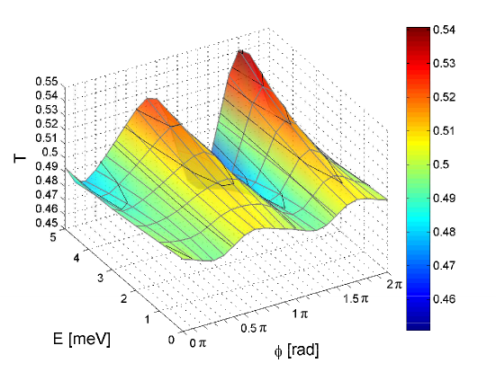
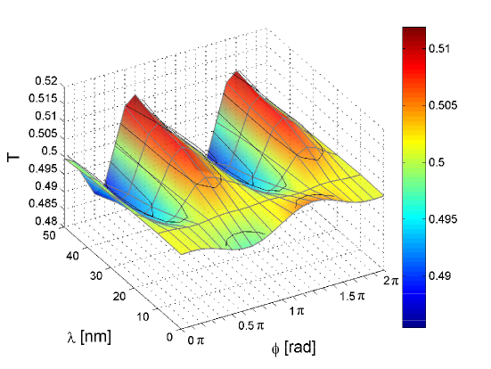
Fig. 4 (a) gives a series of snapshots showing the wave packet as it propagates horizontally along the in-channel and splits more or less symmetrically into two outgoing wave packets traveling along the vertical channels. For rectangular two-soliton magnetic textures of the form Eq. (12) there are the domain width and the angle characterizing the in-plane magnetization across the domain wall which can be varied. For the first simulations of these dependencies for rectangular intersections shown in Figs. 5 and 6, the domain wall width is chosen to be a relatively large nm compared to the perpendicular confinement of the wave packet nm to bring out more clearly the influence of the details of the in-plane components of the magnetization on the wave packet propagation.

In Fig. 6 we show the effects on the transmission into the upper channel when the domain wall width and the magnetization angle are varied. Here, the wave packet is prepared with an energy mean value . The color-coded figures show grid lines (in gray), altitude lines (black) as well as the altitude (as interpolated color map) which should allow the reader to assign a transmission value to every parameter combination shown in the plot. One observes that even for relatively large domain wall widths the influence of the in plane magnetization to the splitting behavior is moderate and, to a very high accuracy, a rectangular intersection provides a 50-50 beam splitter for domain wall states over a wide energy range. This is important for robustness of the splitting ratio under local imperfections.
This situation can be changed, when an electrode is placed asymmetrically onto the junction, as sketched in Fig. 4 (b). The chosen bias value is mV. Note that a static potential cannot close the channel or revert the propagation direction. However, if sufficiently large it provides a mixing of 2D surface states with the channel state and, when spatially confined perpendicular to the out channel, provides a wave guide-like channel, as is shown in the simulation in Fig. 4 (b). This confinement effect, arising from wave number mismatch, has been discussed in the literature.yokoyama Here it is used, to control the splitting ratio which is shown for varying and and nm and in Fig. 8. Dynamically, the confining effect by the (rectangular) gate resembles total internal reflection which arises under glancing incidence onto the potential wall. Tailoring the shape of the electrode helps in effective “funneling” of fermions back into the domain-wall state. This is demonstrated in Fig. 7 (a) and (b) in which we compare the effect of a rectangular versus a triangular bias region.
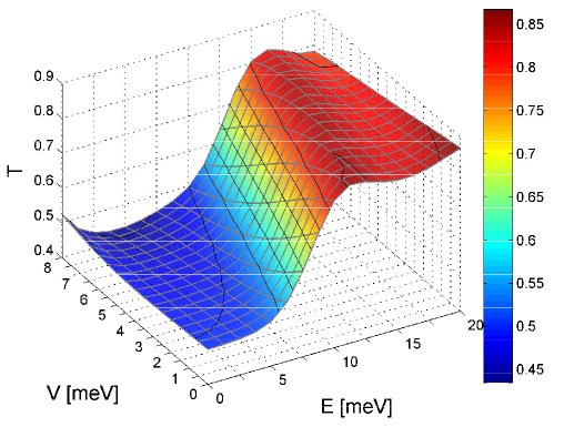
Note that asymmetric biasing of one out channel shows influence on the splitting ratio only when the applied voltage is sufficiently high to energetically move the Dirac fermion out of the magnetization gap (see Figs. 7 and 8). Otherwise it cannot influence significantly the propagation because the addition of a scalar potential does not change the group velocity due to the linear dispersion relation of the channel states.
IV.2 45-degree intersections
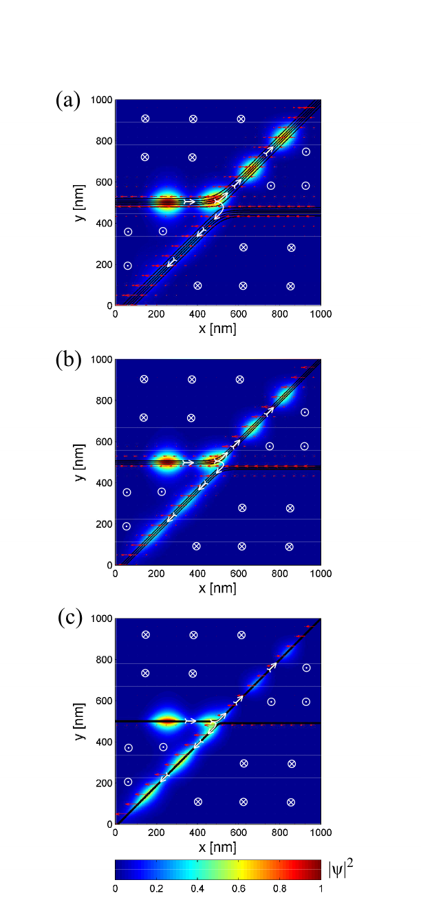
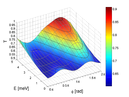
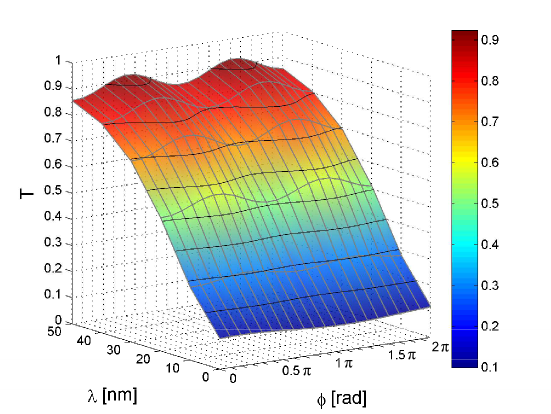
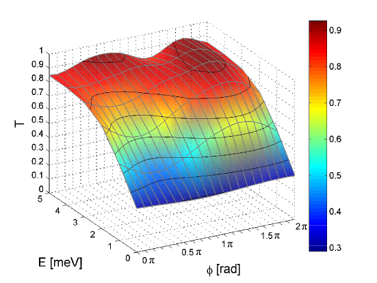
We now turn to 45-degree intersections and study them as a function of (domain-wall type), (channel width), and (mean energy of the wave packet). Fig. 9 shows snapshots of the wave packet as it propagates along the in-channel and splits up at the intersection. It is observed that the preferred out-channel depends on the channel width. For wide channels the upper out-channel is preferred, while for narrow channel width, the lower channel is the preferred exit. This trend arises from an increased overlap of the in-channel wave-packet with the lower out-channel as the channel width decreases, whereas for wide channels, the path of lower momentum transfer wins out. This effect therefore also displays an energy dependence, in contrast to the rectangular case.
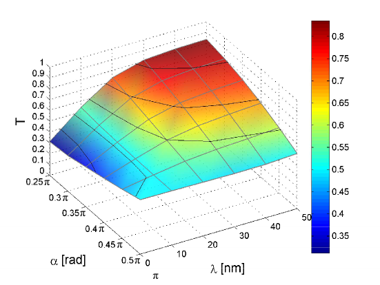
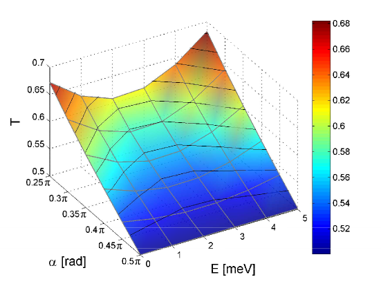
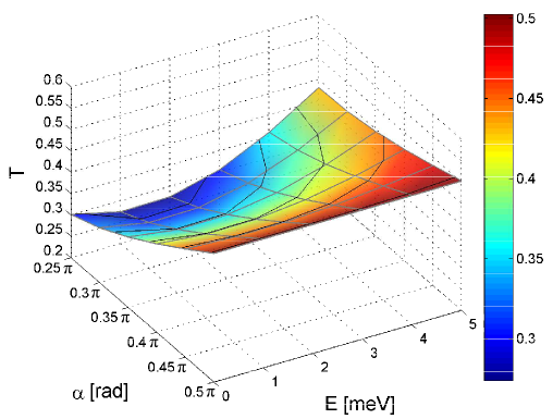
Results from a more systematic analysis are summarized in the following figures. In Fig. 10 we show the transmission as a function of the in plane magnetization angle and the energy mean value for nm. In Fig. 11 we vary the wall width and the in-plane magnetization angle using . Fig. 12 shows the same setup but for meV. Compared to the rectangular intersections (Figs. 6 and 10) the influence of the in-plane magnetization direction is more pronounced. For a fixed interaction angle the most relevant parameter still is the wall width since it determines the degree of asymmetry in the “channel cross-talk” near the junction, as shown in quantitative detail in these figures. As the fermion approaches the intersection it probes the surroundings and begins to leak into the lower out-channel before it detects the upper one.
IV.3 General angles of intersection
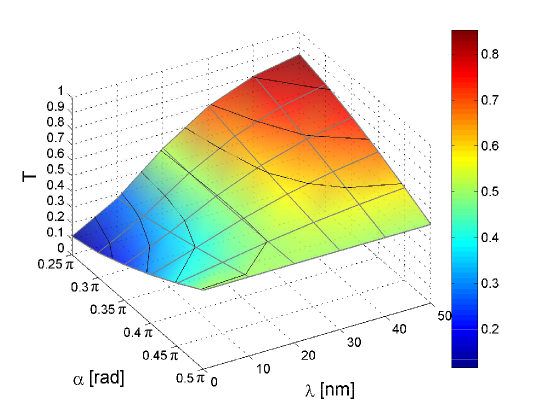
Referring to Fig. 1, general angles of intersection are investigated. In conjunction with the domain-wall thickness the angle of intersection plays the dominant role for establishing the splitting ratio of such an intersection. Results are summarized in the following figures. In Fig. 13 we vary and for . For Fig. 14 we change to meV. Fig. 15 shows the variation of and where and nm. For nm this setup shows a quite different behavior Fig 16. It is remarkable that for small domain-wall widths, relative to the spatial extent of the Dirac fermion wave packet, the transmission into the upper channel decreases for a more acute angle . For large widths, on the other hand, the transmission into this out channel is favored, as one would suspect “intuitively” (see Fig. 12 and 13). This effect is most dominant for wave packets with a center energy of . The two competing effects responsible for this behavior are the difference in spatial (time-dependent) overlap of the incident wave-packet with the two outgoing channels and the “wave-vector” mismatch at the intersection. As already pointed out for the , the behavior of narrow channels is dominated by the former, while wide channels act ballistic, favoring low momentum transfer. In other words, when going from narrow to wide channels, the Dirac fermion scattering behavior changes from quantum-mechanical wave-like to “classical” particle-like. Note that, as per Eq. (14), the (stationary) transverse extent of the wave packet is determined by the asymptotic values of the magnetic texture, while the width of the domain wall independently is determined by the relative importance between anisotropy and exchange contribution in the free energy functional of the magnetization, Eq. (8). Hence, in principle, structural design allows for both situations to occur.
V Summary and conclusions
In summary, we have investigated numerically the dynamics of domain-wall Dirac fermions at the intersections of two linear ferromagnetic domain walls. To model a realistic stable magnetic intersection texture we have used a two-soliton solution of the sine-Gordon equation which establishes the optimality condition for a minimum of a free energy functional accounting for exchange and anisotropy. The time-dependent analysis of chiral fermion propagation is based on a staggered grid numerical scheme to solve the effective (2+1)D Dirac equation. Developed for this particular purpose, it is constructed such that fermion doubling is avoided and absorbing boundary conditions in form of regions of imaginary scalar potential can be incorporated. Details of this model and an extension to (3+1)D can be found elsewhere.Hammerup
The properties of such magnetic intersections as a one-way beam splitters for chiral fermions have been investigated. Based on this study, we can conclude that the splitting ratio for domain-wall fermions at the intersection depends strongly on the angle of intersection and, in case of non-rectangular intersections, on the width of the domain-wall. The latter determines the importance of the wave nature of the fermion onto the transmission behavior: quantum-tunneling dominates the behavior at the intersection when the (transverse) localization length of the domain-wall fermion is large compared to the channel width. For wide domain walls the Dirac fermion behavior at the intersection becomes particle-like. The type of domain wall, as well as the mean energy of the Dirac fermion wave packet, have a weaker influence on the splitting ratio. The former is characterized by the angle of the in-plane magnetization when its z-component goes through zero and allows one to compare Bloch- to Néel-type intersections. Although experimental setups will have imperfections regarding the magnetic structure our results should give a qualitative guide for the splitting behavior in such structures, as long as defects do not destroy the channel states.
External control of of the splitting ratio may become feasible in experiment via asymmetrically biased electric gates placed near the junction. Using specially tapered electrodes, “funneling” of laterally confined fermions back into domain-wall states is shown in our simulation.
Here we have confined our analysis to the intersection of two linear domain walls. If more complex magnetic textures on topological insulators can be realized in experiment, domain-walls can be used as chiral Dirac fermion waveguides, with their mutual intersections acting as beam-splitters as, for example, in a proposal for a domain-wall electric-gate controlled fermion interferometer. hammerAPL
Acknowledgements.
The work is supported by the Austrian Science Foundation under Project No. I395-N16.References
- (1) J. G. Analytis, J. H. Chu, Y. Chen, F. Corredor, R. D. McDonald, Z. X. Shen, and Ian R. Fisher, Phys. Rev. B 81, 205407 (2010).
- (2) Y. L. Chen, J. H. Chu, J. G. Analyits, Z. K. Liu, K. Igarashi, H. H. Kuo, X. L. Qi, S. K. Mo, R. G. Moore, D. H. Lu, et al., Science 329, 659 (2010).
- (3) Y. Xia, D. Qian, D. Hsieh, L. Wray, A. Pal, H. Lin, A. Bansil, D. Grauer, Y. S. Hor, R. J. Cava, and M. Z. Hasan, Nature Physics 5, 398 (2009).
- (4) J. Chen, H. J. Qin, F. Yang, J. Liu, T. Guan, F. M. Qu, G. H. Zhang, J. R. Shi, X. C. Xie, C. L. Yang, K. H. Wu, Y. Q. Li, and L. Lu, Phys. Rev. Lett. 105, 176602 (2010).
- (5) J. G. Checkelsky, Y. S. Hor, R. J. R. J. Cava, and N. P. Ong, Phys. Rev. Lett. 106, 196801 (2011).
- (6) F. Xiu, L. He, Y. Wang, L. Cheng, L. T. Chang, M. Lang, G. Huang, X. Kou, Y. Zhou, X. Jiang, Z. Chen, J. Zou, A. Shailos, and K. L. Wang, Nat. Nanotech. 6, 216 (2011).
- (7) D. Kim, S. Cho, N. P. Butch, P. Syers, K. Kirshenbaum, S. Adam, J. Paglione, and M. S. Fuhrer, Nat. Phys. 8, 459 (2012).
- (8) Y. Wang, F. Xiu, L. Cheng, L. He, M. Lang, J. Tang, X. Kou, X. Yu, X. Jiang, Z. Chen, J. Zou, and, K. L. Wang, Nano Lett. 12, 1170 (2012).
- (9) Z. Ren, A. A. Taskin, S. Sasaki, K. Segawa, and Y. Ando, Phys. Rev. B 85, 155301 (2012).
- (10) J. Honolka, A. A. Khajetoorians, V. Sessi, T. O. Wehling, S. Stepanow, J. L. Mi, B. B. Iversen, T. Schlenk, J. Wiebe, N. B. Brookes, A. I. Lichtenstein, P. Hofmann, K. Kern, and R. Wiesendanger, Phys. Rev. Lett. 108, 256811 (2012).
- (11) P. Wei, F. Katmis, B. A. Assaf, H. Steinberg, P. Jarillo-Herrero, D. Heiman, and J. S. Moodera, Phys. Rev. Lett. 110, 186807 (2013).
- (12) C. Z. Chang et al., Adv. Mat. 25, 1065 (2013).
- (13) T. Yokoyama, Y. Tanaka, and N. Nagaosa, Phys. Rev. B 81, 121401(R) (2010).
- (14) B. Soodchomshom, Phys. Lett. A 374, 2894 (2010).
- (15) J. Yuan, Y. Zhang, J. Zhang, and Z. Cheng, Eur. Phys. J. B, 86 (2013).
- (16) B. D. Kong, Y. G. Semenov, C. M. Krowne, and K. W. Kim, Appl. Phys. Lett. 98, 243112 (2011).
- (17) A. Suwanvarangkoon, I. M. Tang, R. Hoonsawat, B. Soodchomshom, Physica E 43, 1867 (2011).
- (18) Z. Wu, F. M. Peeters, and K. Chang, Phys. Rev. B 82, 115211 (2010).
- (19) T. Misawa, T. Yokoyama, and S. Murakami, Phys. Rev. B 84, 165407 (2011).
- (20) M. M. Vazifeh and M. Franz, Phys. Rev. B 86, 045451 (2012).
- (21) P. Schwab and M. Dzierzawa, Phys. Rev. B 85, 155403 (2012).
- (22) K. Nomura and N. Nagaosa, Phys. Rev. Lett. 106, 166802 (2011).
- (23) A. A. Burkov, D. G. Hawthorn, Phys. Rev. Lett. 105, 066802 (2010).
- (24) Y. Tserkovnyak and D. Loss, Phys. Rev. Lett. 108, 187201 (2012).
- (25) S. T. Chui and V. N. Ryzhov, Phys. Rev. Lett. 78, 2224 (1997).
- (26) J. Castro, S. T. Chui and V. N. Ryzhov, Phys. Rev. B 60, 10271 (1999).
- (27) F. Hassler, A. R. Akhmerov, and C. W. J. Beenakker, Phys. Rev. B 82, 125423 (2010).
- (28) C. Wickles and W. Belzig, Phys. Rev. B 86, 035151 (2012).
- (29) M. Liu, J. Zhang, C. Z. Chang, Z. Zhang, X. Feng, K. Li, K. He, L. L. Wang, X. Chen, X. Dai, Z. Fang, Q. K. Xue, X. Ma, and Y. Wang, Phys. Rev. Lett. 108, 036805 (2012).
- (30) T. Yokoyama, A. V. Balatsky, and N. Nagaosa, Phys. Rev. Lett. 104, 246806 (2010).
- (31) R. Hammer, C. Ertler, and W. Pötz, Appl. Phys. Lett. 102, 193514 (2013).
- (32) X. L. Qi and S. C. Zhang, Rev. Mod. Phys. 83, 1057 (2011).
- (33) J. E. Moore and L. Balents, Phys. Rev. B 75, 121306 (2007).
- (34) L. Fu, C. L. Kane, Phys. Rev. B 76, 045302 (2007).
- (35) X. L. Qi, T. L. Hughes, and S. C. Zhang, Phys. Rev. B 78, 195424 (2008).
- (36) M. Z. Hasan and C. L. Kane, Rev. Mod. Phys. 82, 3045 (2010).
- (37) Q. Liu, C. X. Liu, C. Xu, X. L. Qi, and S. C. Zhang, Phys. Rev. Lett. 102, 156603 (2009).
- (38) R. Jackiw and C. Rebbi, Phys. Rev. D 13, 3398 (1976).
- (39) W. Luo and X. L. Qi, Phys. Rev. B 87, 085431 (2013).
- (40) L. Andrew Wray, Su-Yang Xu, Yuqi Xia, David Hsieh, Alexei V. Fedorov, Yew San Hor, Robert J. Cava, Arun Bansil, Hsin Lin, and M. Zahid Hasan, Nature Physics 7, 32 37 (2011).
- (41) Faxian Xiu, Liang He, Yong Wang, Lina Cheng, Li-Te Chang, Murong Lang, Guan Huang, Xufeng Kou, Yi Zhou, Xiaowei Jiang, Zhigang Chen, Jin Zou, Alexandros Shailos, and Kang L. Wang, Nature Nanotechnology 6, 216 221 (2011).
- (42) Haim Beidenkopf, Pedram Roushan, Jungpil Seo, Lindsay Gorman, Ilya Drozdov, Yew San Hor, R. J. Cava, and Ali Yazdani, Nature Physics 7, 939 943 (2011).
- (43) Duming Zhang, Anthony Richardella, David W. Rench, Su-Yang Xu, Abhinav Kandala, Thomas C. Flanagan, Haim Beidenkopf, Andrew L. Yeats, Bob B. Buckley, Paul V. Klimov, David D. Awschalom, Ali Yazdani, Peter Schiffer, M. Zahid Hasan, and Nitin Samarth, Phys. Ref. B 86, 205127 (2012).
- (44) Su-Yang Xu, Y. Xia, L. A. Wray, S. Jia, F. Meier, J. H. Dil, J. Osterwalder, B. Slomski, A. Bansil, H. Lin, R. J. Cava, M. Z. Hasan, Science 332, p560-564 (2011).
- (45) Chaoyu Chen, Zhuojin Xie, Ya Feng, Hemian Yi, Aiji Liang, Shaolong He, Daixiang Mou, Junfeng He, Yingying Peng, Xu Liu, Yan Liu, Lin Zhao, Guodong Liu, Xiaoli Dong, Jun Zhang, Li Yu, Xiaoyang Wang, Qinjun Peng, Zhimin Wang, Shenjin Zhang, Feng Yang, Chuangtian Chen, Zuyan Xu, and X. J. Zhou, Scient. Reports 3 : 2411, DOI: 10.1038/srep02411, pp 1-6 (2013).
- (46) Cui-Zu Chang, Jinsong Zhang, Xiao Feng, Jie Shen, Zuocheng Zhang, Minghua Guo, Kang Li, Yunbo Ou, Pang Wei, Li-Li Wang, Zhong-Qing Ji, Yang Feng, Shuaihua Ji, Xi Chen, Jinfeng Jia, Xi Dai, Zhong Fang, Shou-Cheng Zhang, Ke He2, Yayu Wang, Li Lu, Xu-Cun Ma, Qi-Kun Xue, Science Vol. 340 no. 6129, pp. 167-170 (2013).
- (47) S. Modak, K. Sengupta, and Diptiman Sen, Phys. Rev. B 86, 205114 (2012).
- (48) Hailin Peng, Keji Lai, Desheng Kong, Stefan Meister, Yulin Chen, Xiao-Liang Qi, Shou-Cheng Zhang, Zhi-Xun Shen, and Yi Cui, Nature Materials 9, 225 229 (2010).
- (49) Thomas Ihn, Nature Materials 9, 187 188 (2010).
- (50) Z. Alpichshev, J. G. Analytis, J. H. Chu, I. R. Fisher, Y. L. Chen, Z. X. Shen, A. Fang, and A Kapitulnik, Phys. Rev. Lett. 104, 016401 (2010).
- (51) G. Rosenberg, M. Franz, Phys. Rev. B 85, 195119 (2012).
- (52) M. Wenin, A. Windisch, and W. Pötz, J. Appl. Phys. 108, 103717 (2010), and references therein.
- (53) Zhenhua Wu, F. M. Peeters, and Kai Chang, Appl. Phys. Lett. 98, 162101 (2011).
- (54) A. Van Esch, L. Van Bockstal, J. De Boeck, G. Verbanck, A. S. van Steenbergen, P. J. Wellmann, B. Grietens, R. Bogaerts, F. Herlach and G. Borghs, Phys. Rev. B 56, 13103 (1997).
- (55) I. Garate and M. Franz, Phys. Rev. Lett. 104, 146802 (2010).
- (56) H. How, R. C. O’Handley, and F. R. Morgenthaler, Phys. Rev. B 40, 4808 (1989).
- (57) Takehito Yokoyama, Jiadong Zang, and Naoto Nagaosa, Phys. Rev. B 81, 241410(R) (2010).
- (58) R. Hirota, J. Phys. Soc. Jpn. 33, 1459 (1972).
- (59) Graham Bowtell and A. E. G. Stuart, Phys. Rev. D 15, 3580 (1977).
- (60) S. Novikov, S. V. Manakov, L. P. Pitaevskii, and V. E. Zarkharov, Theory of Solitons, Consultants Bureau, New York (1984).
- (61) W. Y. Shan, H. Z. Lu, and S. Q. Shen, New J. Phys. 12, 043048 (2010).
- (62) Timur Tudorovskiy and Mikhail I. Katsnelson, Phys. Rev. B 86, 045419 (2012).
- (63) R. Hammer and W. Pötz, Comp. Phys. Comm., in press, http://dx.doi.org/10.1016/j.cpc.2013.08.013
- (64) P. H. Ginsparg and K. G. Wilson, Physical Review D 25, 2649 (1982).
- (65) H. B. Nielsen and M. Ninomiya, Physics Letters B 105, 219 (1981).
- (66) R. Hammer, C. Ertler, and W. Pötz, arXiv:1205.6941
- (67) R. Hammer, W. Pötz, and A. Arnold, J. Comp. Phys. 256, 728 (2014), in press, http://dx.doi.org/10.1016/j.jcp.2013.09.022
- (68) R. Hammer, W. Pötz, and A. Arnold, submitted to Journal of Computational Physics (2013), preprint available at arXiv:1309.3452.