Proton Radiation Damage Experiment on P-Channel CCD for an X-ray CCD camera onboard the Astro-H satellite
Abstract
We report on a proton radiation damage experiment on P-channel CCD newly developed for an X-ray CCD camera onboard the Astro-H satellite. The device was exposed up to 109 protons cm-2 at 6.7 MeV. The charge transfer inefficiency (CTI) was measured as a function of radiation dose. In comparison with the CTI currently measured in the CCD camera onboard the Suzaku satellite for 6 years, we confirmed that the new type of P-channel CCD is radiation tolerant enough for space use. We also confirmed that a charge-injection technique and lowering the operating temperature efficiently work to reduce the CTI for our device. A comparison with other P-channel CCD experiments is also discussed.
keywords:
P-channel CCD , Proton radiation damage , Charge-injection1 Introduction
Charge-coupled devices (CCDs) have an almost 20-years long history as space-borne detectors for X-ray astronomy. The ASCA satellite for the first time employed X-ray photon counting CCDs[1], which were front-illuminated (FI) devices with a depletion layer thickness of about 30 m. Subsequent Japanese X-ray satellite Suzaku carries, in addition to FI CCDs, a back-illuminated (BI) CCD that significantly improved the detection efficiency for soft X-ray photons down to 0.3 keV[2]. However, the depletion layer thickness of the BI CCD was still limited to about 40 m. The X-ray CCDs flown to space so far were all made from P-type silicon wafers, namely N-channel CCDs. Recently, a new type of P-channel CCD has become available with a thick depletion layer of a few hundred m[3]. We employ the new P-channel CCD for Soft X-ray Imager (SXI)[4, 5], a new CCD camera onboard the upcoming Astro-H satellite[6]. Using the P-channel CCD as a BI device with a depletion layer thickness of 200 m, high detection efficiency for both hard and soft X-ray photons can be achieved.
Since P-channel CCDs have no performance experience in space, their radiation hardness is an issue to be examined before launch. The primary source of radiation damage of CCD is cosmic-ray protons, which produce displacement damage in silicon resulting in the formation of carrier traps. Traps in the channel region capture charge carriers during transfer. Then, the charge transfer inefficiency (CTI), a fraction of charge loss per one pixel transfer, is frequently used as a measure of radiation damage for X-ray CCDs. There are several experimental reports indicating that P-channel CCDs are actually radiation harder than conventional N-channel CCDs in terms of the CTI[7, 8, 9]. The greater radiation hardness of P-channel CCDs may be explained by the difference of carrier traps in the two different type of CCDs[10, 7]. Proton-induced formation of divacancy hole traps is considered to be less favorable in a P-channel CCD compared to that of phosphorus-vacancy electron traps in an N-channel CCD[8]. However, it is also suggested that other kind of traps are possibly produced and they may adversely increase the CTI in a P-channel CCD[11].
In relation to the radiation hardness of the device, mitigating the radiation damage effect is also important. A charge-injection (CI) technique is one of such mitigation methods[12, 13, 14]. In this technique, charges are intentionally injected to selected rows which are regularly spaced. Then, the injected charges work as sacrifices to fill traps and following real X-ray-induced charges are transferred with lesser charge loss. The CI has been verified to effectively reduce the CTI in the case of the Suzaku CCDs[12]. Lowering operating temperature of CCDs also reduced the CTI in the case of the Chandra and XMM-Newton CCDs[15, 16].
In this paper, we report on a proton radiation damage experiment on our newly developed P-channel CCD. We here describe how radiation-hard our new device is and how our mitigation methods work once the device is damaged.
2 Experiment
2.1 P-channel CCD used in this experiment
We developed a P-channel BI CCD for the SXI, Pch-NeXT4, in collaboration with Hamamatsu Photonics K.K.[4, 5] (“NeXT” is the former project name of the Astro-H satellite). The Pch-NeXT4 is a frame transfer type CCD with an imaging area of 30.72 mm square. There are 12801280 physical pixels in the imaging area, which will be 640640 logical pixels after on-chip 22 binning. There are four readout nodes, and we nominally use two of them.
There were two CCDs used in this experiment. One was the same type of CCD as Pch-NeXT4, and the other was a smaller size CCD but made in the same manufacturing process as that of Pch-NeXT4. We hereafter refer to the former and the latter as large-CCD and mini-CCD, respectively.
2.2 Experimental setup
We performed our proton radiation damage experiment at the Kyushu University tandem accelerator laboratory. The proton beam current was 50 nA–1 A. Since the direct beam intensity was too strong for our purpose even at a low current of 10 nA (10 year in-orbit equivalent protons would be irradiated in less than one second), we used scattered protons. Use of scattered protons provided another benefit that the large-CCD could be almost uniformly damaged as is the actual case in space.
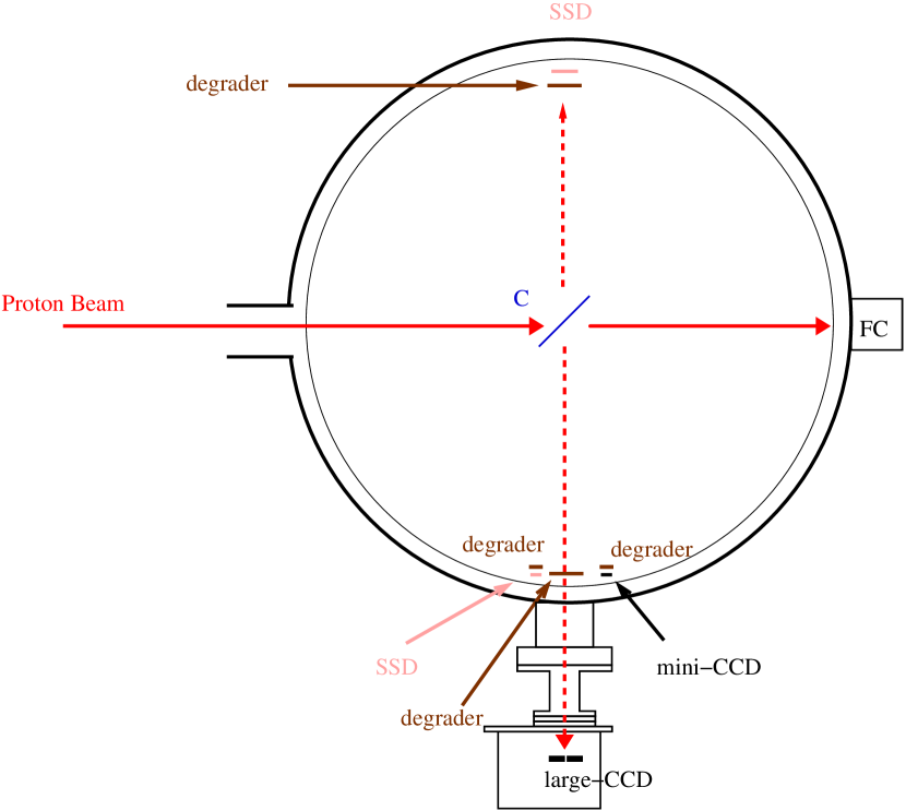
Figure 1 shows a top view of our experimental setup in a scattering chamber of 1 m in diameter. The direct proton beam from the accelerator was scattered at the center of the chamber. The large-CCD, which was installed in a camera body attached outside of the chamber via flange, was located at a right angle to the axis of the proton beam. The proton beam intensity was measured by a Faraday cup, and the energy spectra of the scattered protons were measured by silicon solid-state detectors.
A thin carbon foil of 15 mg cm-2 was used as a scattering target. The first excited energy level of 12C nucleus is about 4.4 MeV that is large enough to remove inelastic scattered protons using a thin aluminum degrader shown in Figure 1. The proton beam energy was 10.5 MeV, and protons incident on the CCDs through degraders were mono-energetic with a peak energy of 6.7 MeV and a full width at half maximum of 0.9 MeV. The protons incident on the CCDs had a range of about 360 m in silicon and easily penetrated our device with a thickness of 200 m. Therefore, energy deposition was relatively uniform along the depth direction with 12–16 keV m-1. The total deposited energy in our device of single proton was about 2.7 MeV.
The large-CCD was operated in the camera body with a temperature of -110∘C and the whole imaging area was irradiated with an 55Fe source. The back bias voltage applied was 35 V. Degradation of the large-CCD was monitored alternating proton irradiation and 55Fe data acquisition. On the other hand, the mini-CCD was placed without a camera system inside the chamber hence its gradual change was not monitored. Instead, the mini-CCD provided a higher dose data because of its closeness to the scattering target than the large-CCD. The 55Fe data of the mini-CCD were taken before and after this experiment in our laboratory.
3 Dose rate in the orbit of the Astro-H satellite and exposed dose in this experiment
In order to determine whether or not our device has radiation hardness enough for space use, it is necessary to estimate the dose rate in space and convert the exposed dose in this experiment to equivalent time in space. For the calculation of the dose rate, we referred to the day-averaged cosmic-ray flux model in the low earth orbit at an inclination angle of 30∘[17], in which the Astro-H will fly. The cosmic-ray model shows that the geomagnetically-trapped proton in the South Atlantic Anomaly (SAA) is by far the largest population among high-energy particle and radiation components which can penetrate a surrounding camera body and reach the CCD inside. At least more than 90% of whole high-energy charged particles exposed to a satellite come from the SAA on a day-average basis (T. Mizuno, private communication). We thus used the SAA proton component alone from the cosmic-ray model.
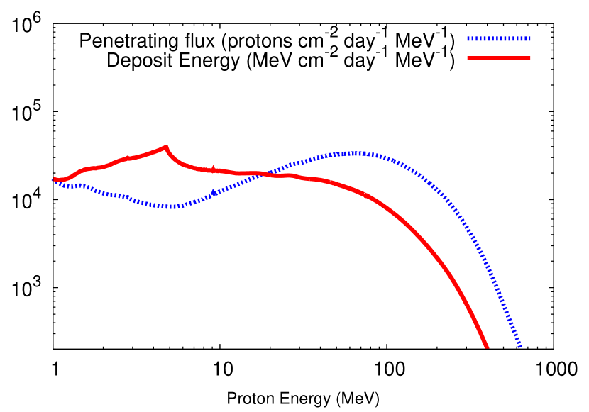
Figure 2 shows a number flux spectrum of protons that penetrate the camera body and reach the CCD. This spectrum was obtained from the SAA proton flux spectrum calculating their energy loss at the passage of the camera body. We approximated the camera body as an aluminum 2 cm thickness shell in this calculation. Figure 2 also shows an energy spectrum deposited from protons at the CCD. This spectrum was obtained multiplying the incoming proton number flux to the CCD with their energy deposition at the CCD that is a function of the proton energy. The incoming number flux spectrum has a peak around 70 MeV, which is the threshold energy to penetrate 2 cm thick aluminum camera body. On the other hand, the deposited energy spectrum shows that lower energy proton population contributes more to the total dose at the CCD. Integrating the deposited energy spectrum, we obtained a dose rate of 2.2 106 MeV cm-2 day-1 or 260 rad year-1. Uncertainty of this value was estimated to be at most a factor of 2 that mainly comes from the SAA proton flux spectrum (T. Mizuno, private communication).
The total proton fluence exposed to the large-CCD and the mini-CCD were about 0.9 and 3.7 109 cm-2, respectively. These values correspond to about 3 and 13 year in orbit, which covers the Astro-H satellite’s mission life time of 5 years. The gradual degradation of the large-CCD was monitored at equivalent times in orbit of 2 days, 2 weeks, 2 months, 6 months, 1 year, 2 years, and 3 years.
4 Result
4.1 Charge transfer inefficiency as a function of proton fluence

Figure 3 shows “stacking plots” made from 55Fe irradiation data, in which pulse heights of the X-ray hit pixels are plotted as a function of row number that is namely half of the number of transfers in our case because of on-chip 22 binning. Each stacking plot shows dense and faint bars which come from Mn K and Mn K data, respectively. In the analysis, we used selected events in which the charge is in a single pixel, not be split into neighboring pixels.
Before the experiment (no fluence), the pulse height decline is barely seen along the row number. On the other hand, after the experiment (the proton fluence exposed was 0.9 109 cm-2), the pulse height clearly decreases as a function of the row number due to an increase of the CTI. The scatter of the pulse height at a given row number also becomes larger, which is more evident in Mn K data in this figure. Comparing the bottom two plots, it is clear that applying the CI technique reduces radiation damage effects of this type: both the pulse height decline and scattering are mitigated. A “saw-tooth shape” seen in the bottom-right plot is the characteristic of applying the CI[14]. The degree of the mitigation is locally maximum just after the charge-injection row and decreases as apart from it. The regularly-spaced charge-injection rows thus make such a periodic pattern in the stacking plot.
The CTI value can be determined by fitting the stacking plots with the following function,
| (1) |
where is the original charge produced by X-ray from 55Fe, is the observed charge after transfer, and is the row number of the pixel hit by the X-ray. Red lines in Figure 3 show the best fit curves only using the Mn K data. The CTI value represents the slope of the stacking plot.
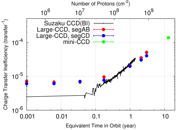
Figure 4 shows the CTI measured without applying the CI technique. The data are plotted as a function of proton fluence (top label) or equivalent time in orbit (bottom label). The colored circles indicate the data taken from our experiment. There are two segments (we call AB and CD) in the large-CCD as we used two readout nodes. Systematic uncertainties dominate and we estimated them as follows. We first divided the data into 10 subsets, derived the CTI value for each subset, and used a scatter of the values as a systematic uncertainty of the data, although they were still smaller than the radius of the circles in the figure. The black dots show the Suzaku BI CCD data actually taken in space. The Suzaku CCD has two 55Fe calibration sources irradiating top corners of the imaging area (far side from readout nodes)[2]. The calibration data was available on a daily basis and summarized on-line111see http://space.mit.edu/XIS/monitor/ccdperf/. We reproduced the CTI values based on the on-line data. Data points at 0.001 year equivalent in orbit mean those before experiment or before launch.
In the case of our P-channel CCD, the CTI was measured to be 7.0 10-6 before experiment and more or less constant until about 1 month or so. It then went up to an order of 10-5 after 4.5 months, and reached to 5.0 10-5 at 3 year. The mini-CCD data point suggests that the CTI would rise with a similar slope up to about 13 year. This time evolution is similar to that of the Suzaku CCD data, especially in terms of the slope after a few months. The apparent difference between their slopes is likely due to the possible uncertainty of factor of 2 in the conversion of proton fluence to equivalent time in orbit.
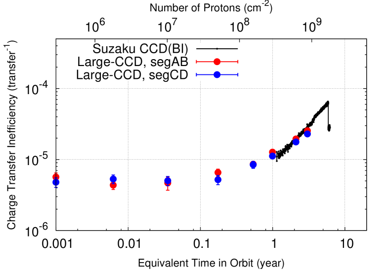
Figure 5 shows the CTI measured with applying the CI technique. The definition of the marks and labels are the same as that of Figure 4. The mini-CCD data with the CI was not available. The Suzaku CCD had been operated without the CI until 1.2 year after the launch. After some verification tests[12], the CI was incorporated in the standard observation mode. Thus, the calibration data with the CI were also only available since about 1 year after the launch. The amount of injected charge was increased from 2 keV equivalent to 6 keV equivalent about 6 years after the launch, which reduced the CTI as shown in Figure 5.
Applying the CI technique reduces not only the CTI values themselves but also its growth rate: the reduction factors are 1.5, 1.8, and 2.0 in the last three data. This suggests that the CI works more efficiently when the device is more damaged at least in our case. The slope is again similar to that of the Suzaku CCD data. Our P-channel data appear to go along with the 6 keV equivalent Suzaku CCD data rather than that of the 2 keV equivalent, although it may not be significant considering the uncertainty.
In the both cases with or without the CI, the degradation of the CCD performance in terms of the CTI is shown to be comparable with that of the Suzaku CCD. Applying the same ground-base CTI correction as those for the Suzaku CCD data to our P-channel CCD data, we can expect to provide the data with the similar quality as the Suzaku data.
4.2 Charge transfer inefficiency as a function of temperature
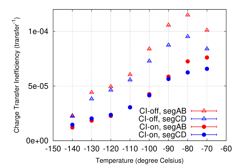
Figure 6 shows the CTI measured as a function of the temperature of the CCD. These data were taken in our laboratory after the proton radiation damage experiment. The values are slightly different from those shown in previous figures even at the same temperature (-110 ∘C) probably because of partially used different electronics. Within the temperature range we tested, it is found that the CTI is smaller at lower temperature. The turn over of the data without the CI at -80∘C is not real. At temperature higher than -90∘C, a charge-trailing became obvious likely due to an increase of the number of traps with a short detrapping time scale of a few CCD clock cycles[2]. In such a situation, using a single pixel data introduces a selective bias and the CTI would be falsely evaluated to be smaller. The difference between the two segments is also smaller at the lower temperature. The effect of applying the CI technique reducing the CTI by about a factor of 2 is almost the same regardless of the temperature.
5 Discussion
We performed a proton radiation damage experiment on our newly developed P-channel CCD and confirmed that its radiation hardness is comparable with that of the Suzaku N-channel CCD actually working in space. Although this result verifies the validity of space use of our P-channel CCD, it might contradict with the previous report that P-channel CCDs are radiation harder than N-channel CCDs.
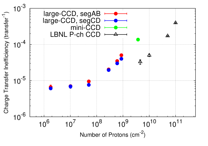
Figure 7 shows a comparison between our results and those reported from another team using a P-channel CCD made by the Lawrence Berkeley National Laboratory (LBNL) [8]. There were two types of the LBNL CCDs whose data were published: one had the “notch” structure and the other did not. The notch structure, a narrow implant in the CCD channel confining a charge packet to a fraction of the pixel volume in an additional potential well, has been known to reduce the CTI[18, 8]. In order to make a direct comparison, we plot our P-channel CCD data without applying the CI and the LBNL P-channel CCD data without the notch structure. A simple comparison along the number of protons irradiated indicates that the LBNL CCD may have about an order of magnitude higher radiation tolerance compared to our CCD. This difference can not be resolved even considering the differences in the incident proton energies and the CCD temperatures between the two experiments. In the LBNL CCD experiment, the incident proton energy and the CCD temperature were 12 MeV and -145∘C, respectively. The energy deposit of the 12 MeV protons is about a factor of 2 lower than that of 6.7 MeV protons used in our experiment. From figure 6, lowering the CCD temperature from -110∘C to -145∘C would reduce the CTI by about a factor of 2. Thus, about a factor of 4 difference can be explained by the difference in the experimental setup. However, significant difference in the radiation hardness still remains between the two P-channel CCDs. The different manufacturing process might be a reason but we do not have a clear answer at this moment.
The LBNL CCD experiment was performed while the devices were unpowered and at room temperature. On the other hand, the large-CCD was powered and cooled during our proton irradiation experiment. However, this difference does not appear to affect the degree of the damage at least in terms of the CTI, considering the relatively smooth connection between the large-CCD and the mini-CCD data. The same conclusion was deduced for N-channel CCDs in a similar proton radiation experiment[19].
The temperature dependency measurement described in section 4.2 was performed in our laboratory about two months after the proton radiation damage experiment. Meanwhile the large-CCD was kept at room temperature. A CTI measurement at the same CCD temperature showed about a 40% worse value compared to the last value obtained at the accelerator laboratory. As we previously noted, this apparent degradation was most likely due to a partial difference of electronics used. This fact then suggests that an annealing at room temperature did not help to restore the radiation damage for our device at least at this damage level.
We confirmed that applying the CI technique and lowering the CCD temperate are both efficient methods to mitigate the radiation damage. Although we tentatively spaced the CI rows 128 row apart in this experiment, the Suzaku CCD camera injects charges at every 54 row. We can expect further reduction of the CTI by narrowing the spacing of the CI rows. Since too many CI rows also reduce an effective imaging area, we need to find out an optimized spacing in future experiments.
The temperature dependence of the CTI of the damaged CCDs varies device to device[15, 16]. Therefore, the understating of the temperature dependence allows us a flexible operation in space where the power available is quite limited. For example, it is a possible option for us to operate the CCD with -100∘C in the initial phase and -120∘C in the later phase of the mission based on this result.
Acknowledgment
We would like to thank all the SXI team members. We also appreciate Dr. T. Mizuno who kindly provided the cosmic-ray flux model used in this report, Dr. M. Kokubun for useful comments, and the Suzaku XIS team at MIT for making the 55Fe monitoring data available on-line. This work was supported by JSPS KAKENHI Grand Number 23000004.
References
- Tanaka et al. [1994] Y. Tanaka, H. Inoue, S. S. Holt, The X-ray astronomy satellite ASCA, PASJ 46 (1994) L37–L41.
- Koyama and et al. [2007] K. Koyama, et al., X-Ray Imaging Spectrometer (XIS) on Board Suzaku, PASJ 59 (2007) 23–33.
- Matsuura and et al. [2006] D. Matsuura, et al., Development of p-Channel Charge-Coupled Device for NeXT, the Next Japanese X-ray Astronomical Satellite Mission, Japanese Journal of Applied Physics 45 (2006) 8904.
- Tsunemi and et al. [2010] H. Tsunemi, et al., Soft x-ray imager (SXI) onboard ASTRO-H, in: Society of Photo-Optical Instrumentation Engineers (SPIE) Conference Series, volume 7732 of Society of Photo-Optical Instrumentation Engineers (SPIE) Conference Series.
- Hayashida and et al. [2011] K. Hayashida, et al., Development of the soft x-ray imager (SXI) for ASTRO-H, in: Society of Photo-Optical Instrumentation Engineers (SPIE) Conference Series, volume 8145 of Society of Photo-Optical Instrumentation Engineers (SPIE) Conference Series.
- Takahashi and et al. [2010] T. Takahashi, et al., The ASTRO-H Mission, in: Society of Photo-Optical Instrumentation Engineers (SPIE) Conference Series, volume 7732 of Society of Photo-Optical Instrumentation Engineers (SPIE) Conference Series.
- Hopkinson [1999] G. R. Hopkinson, Proton damage effects on p-channel CCDs, IEEE Transactions on Nuclear Science 46 (1999) 1790–1796.
- Bebek et al. [2002] C. Bebek, D. Groom, S. Holland, A. Karcher, W. Kolbe, J. Lee, M. Levi, N. Palaio, B. Turko, M. Uslenghi, A. Wagner, G. Wang, Proton radiation damage in p-channel CCDs fabricated on high-resistivity silicon, IEEE Transactions on Nuclear Science 49 (2002) 1221–1225.
- Marshall et al. [2004] C. J. Marshall, P. W. Marshall, A. Wacynski, E. Polidan, S. D. Johnson, A. Campbell, Comparisons of the proton-induced dark current and charge transfer efficiency responses of n- and p-channel CCDs, in: J. D. Garnett, J. W. Beletic (Eds.), Society of Photo-Optical Instrumentation Engineers (SPIE) Conference Series, volume 5499 of Society of Photo-Optical Instrumentation Engineers (SPIE) Conference Series, pp. 542–552.
- Spratt [1997] J. P. Spratt, The effects of nuclear radiation on P-channel CCD imagers, IEEE Radiation Effects Data Workshop (1997) 116–121.
- Bruzzi [2001] M. Bruzzi, Radiation damage in silicon detectors for high-energy physics experiments, IEEE Transactions on Nuclear Science 48 (2001) 960–971.
- Bautz and et al. [2007] M. W. Bautz, et al., Mitigating CCD radiation damage with charge injection: first flight results from Suzaku, in: Society of Photo-Optical Instrumentation Engineers (SPIE) Conference Series, volume 6686 of Society of Photo-Optical Instrumentation Engineers (SPIE) Conference Series.
- Nakajima and et al. [2008] H. Nakajima, et al., Performance of the Charge-Injection Capability of Suzaku XIS, PASJ 60 (2008) 1.
- Uchiyama and et al. [2009] H. Uchiyama, et al., New CTI Correction Method for Spaced-Row Charge Injection of the Suzaku X-Ray Imaging Spectrometer, PASJ 61 (2009) 9.
- Sembay et al. [2004] S. Sembay, A. Abbey, B. Altieri, R. Ambrosi, D. Baskill, P. Ferrando, K. Mukerjee, A. M. Read, M. J. L. Turner, In-orbit performance of the EPIC-MOS detectors on XMM-Newton, in: G. Hasinger, M. J. L. Turner (Eds.), Society of Photo-Optical Instrumentation Engineers (SPIE) Conference Series, volume 5488 of Society of Photo-Optical Instrumentation Engineers (SPIE) Conference Series, pp. 264–271.
- Grant et al. [2006] C. E. Grant, M. W. Bautz, S. E. Kissel, B. LaMarr, G. Y. Prigozhin, Temperature dependence of charge transfer inefficiency in Chandra x-ray CCDs, in: Society of Photo-Optical Instrumentation Engineers (SPIE) Conference Series, volume 6276 of Society of Photo-Optical Instrumentation Engineers (SPIE) Conference Series.
- Mizuno and et al. [2010] T. Mizuno, et al., Monte Carlo simulation study of in-orbit background for the soft gamma-ray detector on-board ASTRO-H, in: Society of Photo-Optical Instrumentation Engineers (SPIE) Conference Series, volume 7732 of Society of Photo-Optical Instrumentation Engineers (SPIE) Conference Series.
- Tsunemi et al. [2004] H. Tsunemi, M. Miki, E. Miyata, Application of a mesh experiment for a proton beam onto the charge-coupled device, IEEE Transactions on Nuclear Science 51 (2004) 2288–2292.
- Miyata et al. [2002] E. Miyata, T. Kamazuka, H. Kouno, M. Fukuda, M. Mihara, K. Matsuta, H. Tsunemi, K. Tanaka, T. Minamisono, H. Tomida, K. Miyaguchi, Proton Irradiation Experiment for X-ray Charge-Coupled Devices of the Monitor of All-Sky X-ray Image Mission Onboard the International Space Station: I. Experimental Setup and Measurement of the Charge Transfer Inefficiency, Japanese Journal of Applied Physics 41 (2002) 7542.