Heat rectification effect of serially coupled quantum dots
Abstract
The nonlinear thermoelectric properties of serially coupled quantum dots (SCQDs) embedded in a nanowire connected to metallic electrodes are theoretically studied in the Coulomb blockade regime. We demonstrate that the electron heat current of SCQDs exhibit a direction-dependent behavior (heat rectification) in an asymmetrical structure in which the electron Coulomb interactions are significant. The phonon thermal conductivity of the nanowire is also calculated, which is used to estimate the phonon heat current. Finally, we discuss how to reduce phonon heat current to allow observation of electron heat rectification behavior in the SCQD junction system in low temperature regime ().
Transport properties of a single semiconductor quantum dot (QD) or nanostructure have been experimentally and theoretically studied in the Coulomb blockade regime for application as a single electron transistor due to its functionality of charge filtering.1-5 It has been proposed that the QD system can be used as a qubit for quantum computation.6 For the realization of solid state quantum computer, many experimental studies have been devoted to the tunneling current of serially coupled double quantum dots (DQDs).7 The serially coupled DQDs can act as a spin filter when the the Pauli spin blockade condition is met.7 Recent experimental works have extended DQDs to triple quantum dots (TQDs) for studying multi electron spin blockade process and leakage current arising from phonon assisted tunneling.8-10 However, there has been little study on the energy transfer of such nanostructure junctions including DQDs and TQDs. The understanding of energy transfer and heat extraction of the nanostructure junction is also crucial in the implementation of solid state quantum register, because the heat accumulation will degrade the performance of quantum computation.
Apart from that, solid state coolers and power generators at nanoscale may be important in the integration of quantum device circuits.11 Unlike electronic nanodevices, it is still a challenge to realize nanoscale solid state thermoelectric devices.11 Up to date, several theoretical studies on the thermoelectric properties of nanostructures have been reported.12-17These studies have focused on the thermoelectric properties of QD junctions in the linear response regime rather than nonlinear response. To the best of our knowledge, the nonlinear electron heat transport properties of serially coupled QDs (SCQDs) including DQDs and TQDs have not been reported. Here, we demonstrate that DQDs and TQDs with asymmetrical structures can exhibit direction-dependent electron heat current in the absence of phonon heat current. Such a rectification effect of electron heat current may be masked by the phonon heat current, since phonon carriers dominate the contribution of heat current in nanowires with large cross-section. Thus, only for SCQDs embedded in a thin nanowire, such heat rectification effect may be realized.
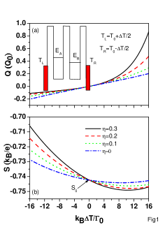
Here, we consider nanoscale semiconductor QDs, in which the energy level separations are much larger than their on-site Coulomb interactions and thermal energies. Thus, only one energy level for each quantum dot needs to be considered. The extended Hubbard model and Anderson model are used to describe the SCQD system connected to the metallic electrodes.15 Using the Keldysh-Green’s function technique [15,18], the charge and heat currents of a DQD [as shown in the inset of Fig. 1(a)] are calculated according to
| (1) | |||||
| (2) |
where is the transmission coefficient.15,16 denotes the Fermi distribution function for the left (right) electrode. and denote the chemical potentials of the left and right leads, respectively, with their average denoted by . is the voltage across the SCQD junction. denotes the equilibrium temperature of the left (right) electrode. and denote the electron charge and Planck’s constant, respectively. denotes the transmission function, which can be calculated by evaluating the on-site retarded Green’s function (GF) and lesser GF [15]. The indices and j denote the th QD and the th QD, respectively. Based on the equation of motion method, we can obtain analytical expressions of all GFs in the Coulomb blockade regime. Details are provided in Ref. 15. In the weak interdot limit (, where and denote the electron interdot hopping strength and on-site Coulomb interaction, respectively) the transmission function can be recast into a simple closed-form.16-17
To study the direction-dependent heat current, we let and , where is the average of equilibrium temperatures of two side electrodes and is the temperature difference across the junction. Because the temperature gradient can induce a significant electrochemical potential difference , now denoted by (the thermal voltage), it is important to take into account the shift of energy level () in each dot according to the expression , where denotes the fraction of voltage difference shared by QD . The value of depends on the location, shape and dielectric constant of the QD. For simplicity, we assume that is determined solely by the QD location and the voltage difference is uniformly distributed among QDs. This is a valid approximation when the dielectric constants of the QD and the surrounding material are similar, which leads to a uniform electric filed in the junction system. Let denotes the center position of QD with respect to the mid point of the junction and the separation of two electrodes is , then the electrostatic potential energy due to the uniform electric field seen by an electron in QD is simply ( is along the direction of transport). For weak field and symmetric wave function in each QD, the energy correction due to the linear term vanishes up to first order. Thus, we have . For the DQD junction, we assume and .
We have numerically solved Eqs. (1) and (2) for SCQD junctions. We first determine by solving Eq. (1) with J = 0 (the open circuit condition) for a given , and an initial guess of the average one-particle and two-particle occupancy numbers, and for each QD. Those numbers are then updated according to Eqs. (5) and (6) of Ref. 16 until self-consistency is established. Once is solved, we then use Eq. (2) to compute the heat current. We have adopted the following physical parameters and . If we adopted an energy unit , then , and .
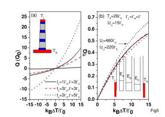
Figure 1(a) shows the heat current () as a function of temperature difference () for a DQD with various values of , where . The QD energy levels are and . The inter-dot Coulomb energy is . A nonlinear behavior of heat current is clearly seen in Fig. 1(a), where the heat current in the forward temperature bias () is much larger than that in the reversed temperature bias (). This nonlinear behavior in heat current leads to significant thermal rectification effect for the DQD junction system, which depends strongly on . When , the electrochemical potential yielded by temperature bias will not shift the QD energy levels. Consequently, the thermal rectification effect disappears even though we have . Fig. 1(b) shows the corresponding Seebeck coefficient. denotes the Seebeck coefficient in the linear response () regime. A negative value implies that electrons of the hot side electrode diffuse to the cold side electrode via the energy levels above .15 On the other hand, holes of the electrodes are the major diffusion carriers if we have a positive . Holes are defined as the empty states which are below the Fermi energy of electrodes. Note that the relationship between the electron heat current and Seebeck coefficient is highly nonlinear, it is hard to verify the electron heat rectification via the measurement of , even though is not influenced by the phonon heat current. In this study we shall consider configurations that lead to large electron heat current, which is in contrast to the Pauli spin blockade configuration considered in Refs. 7 and 15.
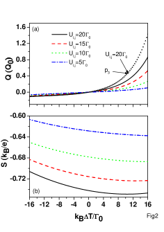
To further clarify the rectification behavior shown in Fig. 1(a), we show the heat current () of the DQD junction for various interdot Coulomb interactions () in Fig. 2(a). Other physical parameters are the same as those in Fig. 1(a) for . With decreasing , the magnitude of is seriously reduced for large forward temperature bias, and at the same time, the rectification behavior is seriously suppressed. Once all electron Coulomb interactions are excluded, the rectification behavior is very small (not shown here). This implies that the heat current rectification is directly related to the electron Coulomb interactions, especially the interdot Coulomb interactions. Note that there are eight configurations for a electron with spin to diffuse from the hot electrode to the cold electrode [see Eq. (3) of Ref. 16]. To reveal which channel dominates the heat current , the curve labeled by (which is calculated by including the configuration alone) is also plotted in Fig. 2(a) (triangles line). In the reversed temperature bias, it matches very well with the solid line (including eight configurations), whereas its magnitude is larger than that of solid line in the forward temperature bias. This is mainly because the channel allows electrons of the cold electrode to transport heat to hot side. From the results of curve labeled , the heat current is determined by the joint density of states arising from two poles and , which are separated by in the small limit. This explains why the heat current in the forward temperature bias is much larger than that in the reversed temperature. Fig. 2(b) shows the corresponding Seebeck coefficients () for various values of . We see that diminishes as the interdot Coulomb interaction decreases, since the tunneling energy levels become closer to the Fermi energy of electrodes and the contribution due to holes increases.
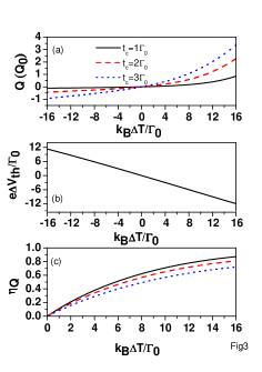
To design a good thermal rectifier, it is important to have large heat current and high rectification efficiency. Fig. 3 shows the heat current, and rectification efficiency () for different interdot hopping strengths. Other physical parameters are the same as those in Fig. 1(a) for . To elucidate the rectification efficiency of QD junction system, we define , where denote the forward (reversed) temperature bias. We find that the rectification efficiency is suppressed when increases (accompanying an increasing heat current). On the other hand, is insensitive to the variation of even in the nonlinear response regime. In the linear response regime, is very insensitive to as long as .16
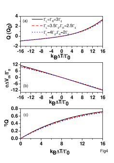
To examine the effect of coupling between QDs and electrodes on thermal rectification efficiency, Fig. 4 shows the heat current, and rectification efficiency for different tunneling rate values, while keeping and . Other physical parameters are the same as those in Fig. 1(a) for . Unlike parallel QD cases, where very asymmetrical tunneling rates ( or ) are required to observe thermal rectification effect,13 the thermal rectification behavior of SCQDs is not sensitive to the coupling condition between QDs and electrodes. Based on the results of Figs. (1)-(4), the heat current rectification of SCQD is very robust. Ref. 19 attempted to observe thermal rectification experimentally in a single QD system with two levels by using the measurement of in the linear response regime (). Our calculated results imply that it is difficult to verify the existence of electron thermal rectification in either the linear or nonlinear response regime via the measurement of due to unclear relationship between and .
So far, the results of Figs. 1-4 are related to the heat rectification of DQDs. To build a large temperature bias (large ) across the junction, it is essential to consider large number of coupled QDs in the system in order to reduce thermal current arising from phonons.11,17 For simplicity, we consider the case of a TQD junction as shown in the inset of Fig. 5, similar to the structure considered in Ref. 9. The expressions of Eqs. (1) and (2) are still valid for the TQD junction, whereas we need to consider a more complicated transmission coefficient.17 The TQD junction has 32 configurations for an electron with spin to tunneling between two metallic electrodes.17 Figure 5 shows the heat current (), and heat rectification efficiency for different physical parameters in the TQD junction with , , and . The heat current has a remarkable enhancement for and . If we adopt , then , , , , and in Fig. 5. Based on these physical parameters, it is possible to fabricate a realistic TQD junction system to realize the heat rectification behavior as predicted theoretically. As an example, we have calculated the above physical parameters for an QD junction system within the effective mass approximation.20 For a disk-shaped QD with radius and height , the intradot Coulomb interaction is . A barrier with width leads to , and . Using these realistic physical parameters, we obtain the heat current and heat rectification efficiency versus temperature for QD junction and show them as triangle marks in Fig. 5. Compared to the dotted line, the heat current is suppressed, whereas the rectification efficiency is enhanced. This result indicates that the heat current is not a monotonic increasing function of . Other systems of interest include GexSi1-x QDs embedded in Si nanowires in which the confined carriers are holes.
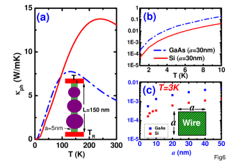
In the presence of phonon heat current, the rectification efficiency obtained above will be suppressed. To estimate the phonon heat current, we calculate the thermal conductivities of nanowires by using the method and physical parameters given in our previous work for studying semiconductor quantum wells.21 The low temperature phonon thermal conductivity of nanowire was reported in Ref. 22 for studying the thermoelectric properties of Kondo insulator nanowires. Figure 6(a) shows the calculated phonon thermal conductivity () of silicon and nanowires with lateral dimension as a function of temperature. In diagram (b) of silicon nanowire is smaller than that of GaAs nanowire in the low temperature regime. Fig. 6(c) shows the quantum size effect on of silicon and nanowires at . The results of Fig. 6(c) imply that the electron heat rectification behavior as shown in Fig. 5 is easier to observe at low temperatures in silicon system than in system. We obtain a phonon heat current for a single silicon nanowire with cross-sectional area and length at . This indicates that the results of Fig. 5 will be washed out in the presence of phonon heat current. To reduce the phonon heat current, we design a special structure as shown in the inset of Fig. 6(a) with a smaller cross-sectional area , which can be realized by advanced nanofabrication technique. The phonon heat current of silicon nanowire can reduce to about for , which is closes to the heat current, considered in Fig. 5. It is conceivable that the phonon thermal conductivity of a nanowire can be further reduced by the interface scattering effect due to the presence of QDs.23 Therefore, of silicon nanowire in the presence of GexSi1-x QDs can be smaller than at . So far, many theoretical mechanisms employing phonon or photon carriers for thermal rectifiers have been proposed.24-26 However, few literatures have reported thermal rectification effect experimentally.27
Summary
The heat current of SCQD system including DQD and TQD under finite temperature bias has been investigated theoretically. It is shown the thermal rectification behavior can arise from the electron energy transport in the absence of phonon heat current. Compared to a single QD with two levels19 or parallel multiple QDs,13 the condition for thermal rectification behavior of SCQD system is easier to realize. For example, one could consider the fabrication method of Ref. 9. The presence of phonon heat current will seriously suppress the thermal rectification efficiency. Thus, reducing the phonon heat current via smart nanostructure design becomes a key issue to the observation of direction-dependent electron heat current.
Acknowledgments
This work was supported in part by the National Science Council of the Republic of China under Contract Nos. NSC 101-2112-M-008-014-MY2, and NSC 101-2112-M-001-024-MY3.
E-mail address: mtkuo@ee.ncu.edu.tw
E-mail address: yiachang@gate.sinica.edu.tw
References
- (1) L. J. Guo, E. Leobandung and S. Y. Chou, Science. 275, 649 (1997).
- (2) H. Ishikuro and T. Hiramoto, Appl. Phys. Lett. 71, 3691(1997).
- (3) C. Joachim, J. K. Gimzewski and A. Aviram, Nature 408, 541 (2000).
- (4) D. M. T. Kuo, and Y. C. Chang, Phys. Rev. Lett. 99, 086803 (2007).
- (5) Y. C. Chang and D. M. T. Kuo, Phys Rev B 77, 245412 (2008).
- (6) R. Hanson, L. P. Kouwenhoven, J. R. Petta, S. Tarucha, and L. M. K. Vandersypen, Rev. Mod. Phys. 79, 1217 (2007).
- (7) Ono K, Austing DG, Tokura Y, Tarucha S Science 297, 1313 (2002).
- (8) M. Busl, G. Granger, L. Gradreau, R. Sanchez, A. Kam, M. Pioro-Ladriers, S. A. Studenikin, P. Zawadzki, Z. R. Wasilewski, A. S. Sachrajda and G. Platero, Nature Nanotechnology 7, 1 (2013).
- (9) S. Amaha, W. Izumida, S. Teraoka, S. Tarucha, J. A. Gupta and D. G. Austing, Phys. Rev. Lett. 110, 016803 (2013).
- (10) F. R. Braakman, P. Barthelemy, C. Reichi, W. Wegscheider, and L. M. K. Vandersypen, Appl. Phys. Lett. 102, 112110 (2013).
- (11) M. Zebarjadi, K. Esfarjania, M.S. Dresselhaus, Z.F. Ren and G. Chen, Energy Environ Sci 5, 5147 (2012).
- (12) P. Murphy, S. Mukerjee, and J. Moore, Phys. Rev. B 78, 161406 (2008).
- (13) D. M. T. Kuo and Y. C. Chang, Phys. Rev. B 81, 205321 (2010).
- (14) J. Liu, Q. F. Sun, and X. C. Xie, Phys. Rev. B 81, 245323 (2010).
- (15) D. M. T. Kuo, S. Y. Shiau and Y. C. Chang, Phys. Rev. B 84, 245303 (2011).
- (16) D. M. T. Kuo and Y. C. Chang, Nanoscale Res. Lett. 7, 257 (2012).
- (17) D. M. T. Kuo and Y. C. Chang, Nanotechnology 24, 175403 (2013) and arXiv:1209.0506.v3
- (18) H. Haug and A. P. Jauho, Quantum Kinetics in Transport and Optics of Semiconductors (Springer, Heidelberg, 1996).
- (19) R. Scheibner, M. Konig, D. Reuter, A. D.Wieck, C. Gould, H. Buhmann and L. W. Molenkamp, New. J. Phys. 10, 083016 (2008).
- (20) D. M. T. Kuo and Y. C. Chang, Phys. Rev. B 61, 11051 (2000).
- (21) Y. C. Tseng, D. M. T. Kuo and Y. C. Chang, J. Appl. Phys. 113, 113706 (2013).
- (22) Y. Zhang, M. S. Dresselhaus, Y. Shi, Z. Ren, and G. Chen, Nano Lett. 11, 1166 (2011).
- (23) D. L. Nika, E. P. Pokatilov, A. A. Balandin, V. M. Formin, A. Rastelli, and O. G. Schmidt, Phys. Rev. B 84, 165415 (2011).
- (24) B. Li, L. Wang and G. Casati, Phys. Rev. Lett. 93 184301 (2004).
- (25) B. B. Hu, L. Yang, and Y. Zhang Phys. Rev. Lett. 97 124302 (2006).
- (26) C. R. Otey, W. T. Lau, and S. H. Fan, Phys. Rev. Lett. 104 154301 (2010).
- (27) C. W. Chang, D. Okawa1, A. Majumdar, and A. Zettl, Science 17 1121 (2006).
Figure captions