Evidence for the coexistence of Dirac and massive carriers in under hydrostatic pressure
Résumé
Transport measurements were performed on the organic layered compound under hydrostatic pressure. The carrier types, densities and mobilities are determined from the magneto-conductance of . While evidence of high-mobility massless Dirac carriers has already been given, we report here, their coexistence with low-mobility massive holes. This coexistence seems robust as it has been found up to the highest studied pressure. Our results are in agreement with recent DFT calculations of the band structure of this system under hydrostatic pressure. A comparison with graphene Dirac carriers has also been done.
pacs:
72.15.Gd, 72.80.LeI Introduction
The layered organic material (aI3), which has been studied since the 1980s,Mishima95 ; Tajima00 ; Tajima06 ; Tajima09 ; Kino06 has recently attracted renewed interest because it reveals low-energy massless Dirac fermions under hyrdostatic pressure ( GPa).Kobayashi07 Compared to graphene, certainly the most popular material with low-energy Dirac fermionsNovoselov05 or electronic states at the surface of three-dimensional topological insulators,TI aI3 is strikingly different in several respects. Apart from the tilt of the Dirac cones and the anisotropy in the Fermi surface,Kobayashi07 ; Goerbig08 its average Fermi velocity is roughly one order of magnitude smaller than that in graphene. This, together with an experimentally identified low-temperature charge-ordered phase at ambient pressure,Mishima95 ; Tajima00 indicates the relevance of electronic correlations. Indeed, because the effective coupling constant for Coulomb-type electron-electron interactions is inversely proportional to the Fermi velocity, it is expected to be ten times larger in aI3 than in graphene. The material aI3 thus opens the exciting prospective to study strongly-correlated Dirac fermions that are beyond the scope of graphene electrons.CastroNeto09 .
Another specificity of aI3 is the presence of additional massive carriers in the vicinity of the Fermi level, as recently pointed out in ab-initio band-structure calculations.Alemany12 However, the interplay between massless Dirac fermions and massive carriers has, to the best of our knowledge, not yet been proven experimentally. Finally, one should mention a topological merging of Dirac points that is expected for high but experimentally accessible pressure.Kobayashi07 ; Montambaux09
Here, we present magneto-transport measurements of aI3 crystals under hydrostatic pressure larger than GPa where Dirac carriers are present. We show not only the existence of high-mobility Dirac carriers as reported elsewhere,Tajima06 ; Tajima11 ; Tajima12 but we prove also experimentally the presence of low-mobility massive holes, in agreement with recent band-structure calculations.Alemany12 The interplay between both carrier types at low energy is the main result of our studies. Furthermore, we show that the measured mobilities for the two carrier types hint at scattering mechanisms due to strongly screened interaction potentials or other short-range scatterers.
The remainder of the paper is organized as follows. In Sec. II, we present the experimental set-up and the results of the magneto-transport measurements (Sec. II.1) under hydrostatic pressure. The subsection II.2 is devoted to a discussion of the temperature dependence of the carrier densities, in comparison with the model of (A) massless Dirac fermions and (B) massive carriers. Furthermore thermopower measurements are presented to corroborate the two-carrier scenario. The measured temperature dependence of the extracted carrier mobilities is exposed in Sec. II.3, and a theoretical discussion of the experimental results, in terms of short-range (such as screened Coulomb) scatterers may be found in Sec. III. We present our conclusions and future perspectives in Sec. IV.
II Experimental evidence for coexisting Dirac and massive carriers
The single crystals of aI3 used in our study have been synthesized by electro-crystallization. Their typical size is mm2 ( plane) x m ( direction). Six nm thick gold contacts were deposited by Joule evaporation on both sides of the sample, allowing for simultaneous longitudinal and transverse resistivity measurements. A picture of one of the three samples studied is shown in the inset of figure 1. The resistivities were measured using a low-frequency ac lock-in technique. The magnetic field , oriented along the axis, was swept between and T at constant temperature between and K. To account for alignment mismatch of patterned contacts, the longitudinal (transverse) resistivity has been symmetrized (anti-symmetrized) with respect to the orientation of to obtain even [] and odd [] functions respectively. Hydrostatic pressure was applied at room temperature in a NiCrAl clamp cell using Daphne 7373 silicone oil as the pressure transmitting medium. The pressure was determined, at room temperature, using a manganine resistance gauge located in the pressure cell close to the sample. The values given below take into account the pressure decrease during cooling.
II.1 Magneto-transport measurements
The analysis of our data is based on the study of the magneto-conductivity and is similar to the one presented in Ref. Kim93, for multi-carrier semiconductor systems. The magneto-conductivity is obtained from the measured resistivity tensor by means of . For a single carrier system, its analytical expression readsZakrzewski72 ; Dziuba74
| (1) |
where , is the electron charge, the mobility, and is the carrier density.
Figure 1 displays a typical magneto-conductivity curve of aI3 under pressure, where two ‘plateaus’ can be clearly seen. As conductivity in aI3 has a strong 2D character, conductivity is shown both as 3D conductivity () and as 2D conductivity ( of each BEDT-TTF plane) according to . As conductivity is additive, in a two-carrier system, the contributions of each carrier type A and B can be added,
| (2) |
The two “plateaus”, observed in Fig. 1, indicate the existence of two different carrier types ( or ) with significantly different mobilities. From this curve, we can extract the mobilities, , of each carrier type, their zero-field conductivities, , and their carrier densities, , by .
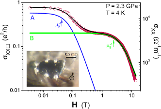
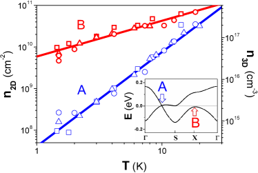
Figure 2 shows magneto-conductivity curves of aI3 at a fixed pressure for several temperatures. The previous analysis has been repeated for each of these magneto-conductivity curves to obtain the densities (Fig. 3) and mobilities (Fig. 4) for each carrier type as a function of temperature and for three different pressures, , and GPa. The strong temperature dependence of the carrier density is a signature that temperature is higher than for both A and B carriers even at the lowest measured temperature, K. This low Fermi temperature hints at the absence of charge inhomogeneities that prevent the approach of the Dirac point in graphene on Si02 substrates.Martin08
II.2 Temperature dependence of the carrier densities
The carrier density can be calculated from , where is the Fermi-Dirac distribution and is the density of states for massive () and Dirac () carriers:CastroNeto09

| (3) |
| (4) |
where and are valley and spin degeneracies and is the effective mass of massive carriers described by a Schrödinger equation. In aI3 under pressure, two Dirac cones but only one massive band exist at the Fermi level.Alemany12 For large temperatures, , the carrier density depends linearly on temperature for massive carriers and quadratically for Dirac carriers:
| (5) |
| (6) |
Figure 3 represents the measured temperature dependence of the mobilities and reveals a power-law behavior, . Indeed one obtains an exponent of for the low-mobility carriers (B), in good agreement with what [Eq. (5)] expected for massive carriers, whereas one finds for the high-mobility carriers (A), as roughly expected for massless Dirac particles [Eq. (6)].
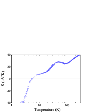
Besides, the nature of the carriers can be extracted from Hall measurements. Furthermore, we have performed thermopower measurements under pressure on a second sample (Figure 5). These data show a sign change for the Seebeck coefficient (S) around 5K. Thermopower is the voltage per unit of temperature produced by a thermal gradient. The carrier type determines the sign while the density and mobility of the carriers establish the amplitude. Thus, a sign change of the thermopower indicates that the relevant carriers at low temperature have a different charge than those at high temperature, requiring a two-carrier scenario.
In agreement with Ref. Tajima12, , A carriers which dominate the low-field conduction are electrons. On the contrary, at large fields the conduction is dominated by holes (B carriers). Notice that our results are consistent with ab-initio calculations of the band structure of aI3 under a pressure of GPa (inset of figure 3)Alemany12 and do not depend on pressure (within the range GPa). This supports the idea that massless and massive particles coexist in a broad pressure range. However, since in the whole temperature range under study, both Dirac electrons and Dirac holes are excited. Thus there are indeed not two but three carrier types: Dirac holes, Dirac electrons and massive electrons. For , the electron and hole densities are actually identical (semimetal with symmetric band structure): . The absence of a third ‘plateau’ in the magneto-conductivity data allows us to consider that Dirac electrons and holes have roughly the same mobilities: . Therefore, the results obtained in figure 3 and 4 still hold when we consider two types of Dirac carriers (electrons and holes) in addition to the massive holes. This analysis allows us to avoid using Hall effect measurements for the determination of carrier densities. Indeed, Hall effect interpretation becomes challenging as Dirac electron and hole contributions partially compensate, leading to the determination of only an ‘effective’ Dirac carrier density, and they are both mixed with massive carriers contribution. This problem is solved here by analyzing the magneto-conductivity where all carriers contributions are additive.
II.3 Mobilities
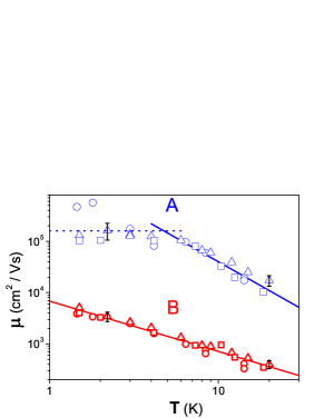
The effective mass of the massive carriers has been extracted from Eq. (5). The obtained value is quite small ( is the free electron mass). Meanwhile, from Eq. (6), m/s can be extracted, in agreement with previous theoreticaKobayashi07 ; Goerbig08 and experimental estimates.Tajima12 In Fig. 3, no significant variation of this argument is observed upon sweeping pressure (which should appear as a vertical shift of the line). This indicates that does not change with pressure. In principle, pressure should enhance hopping while reducing the unit cell volume. Thus, an enhancement of the with pressure could be expected according to the approximate expression , where is the hopping integral. This expression can be simplified by means of Harrison’s law () into . As pressure slightly modifies the lattice constant (GPa Kondo09 ), is expected to vary by the same order of magnitude which is smaller than our current experimental uncertainty. This accounts for the apparent absence of pressure effects on the carrier density in the range GPa.
In Fig. 4, the mobility of the Dirac carriers (A) reaches cm2/Vs at low temperatures ( K), a value comparable to already published values.Tajima06 It is quite high compared to typical graphene on values ( to cm2/Vs) but similar to suspended graphene and graphene on BN mobilities at very low carrier density.Bolo08 ; Kim10 ; kimBN On the other hand, the mobility for massive carriers is cm2/Vs at K, which is two orders of magnitude smaller than for Dirac carriers. The temperature dependence of the mobility follows power laws for both massive (exponent ) and Dirac carriers (exponent ). Moreover, the Dirac carrier mobility seems to saturate at . A similar saturation has been reported in others Dirac systems.Chen08 Table 1 summarizes the main parameters of massive and Dirac carriers in aI3, in comparison with graphene on .
| Quantity | Massive carriers in aI3 | Dirac carriers in aI3 | Dirac carriers in graphene/ Monteverde10 |
|---|---|---|---|
| (K) | |||
| (cm-2) | |||
| (m/s) | |||
| (4K) (cm2/Vs) | |||
| () | |||
| (fs) |
III Theoretical discussion in terms of screened Coulomb or short-range scatterers
In order to better understand the difference in the mobility, we investigate the ratio , in terms of the scattering times and for the massless Dirac and massive carriers, respectively. Furthermore, is the density-dependent cyclotron mass of the Dirac carriers, in terms of the Fermi energy . The scattering times may be obtained from Fermi’s golden rule (for )
| (7) |
in terms of the impurity density , the matrix element , and the density of states (4) for Dirac and (3) for massive carriers. We consider implicitly that both carrier types are affected by the same impurities, and the matrix element is independent of for short-range impurity scattering. Apart from atomic defects, screened Coulomb-type impurities approximately fulfill this condition, as it may be seen within the Thomas-Fermi (TF) approximation. Indeed, the screening length of the Coulomb interaction is dominated by the Thomas-Fermi wave vector m-1 of the massive carriers, for an effective Bohr radius , whereas the Thomas-Fermi wave vector for massless Dirac carriers m-1, for a density cm-1 and a fine-structure constant . The Thomas-Fermi wave vector is thus roughly one order of magnitude larger than the Fermi wave vector of the massive carriers, which is itself much larger than that of the Dirac carriers. The screened Coulomb potential for -type carriers may therefore be approximated by its value, , which is thus the same for both carrier types, as mentioned above. Here, is the permittivity of the dielectric environment and is the dielectric function calculated within the Thomas-Fermi approximation.
In view of the above considerations, we thus obtain, for the mobility ratio in the limit
| (8) |
which does neither depend on the form of the matrix element nor on the impurity density. One expects a ratio in the range, whereas the measured ratio is at K. Notice that for , that is in the experimentally relevant regime here, one may replace the energy dependence in the density of states of the massless Dirac carriers by a linear dependence in temperature, , such that one expects a linear temperature dependence of the mobility ratio (8), in agreement with our experimental findings ( for , see Fig. 4).
IV Conclusions
To conclude, we present an interpretation of magneto-transport in aI3 that indicates that both massive and Dirac carriers are present even at high pressures. Thermopower measurements performed on one of the three studied samples are also in agreement with this two carrier scenario.
So far in the literature, the conduction in this system has been attributed solely to Dirac carriers.Tajima06 Moreover, this coexistence holds with little perturbation in the whole range of pressure under study. As Dirac carriers have high mobility, they dominate the conduction at low magnetic field and high temperatures. On the contrary, for high magnetic fields and low temperatures, the massive holes drive the conduction properties. This crossover can be clearly seen from our magneto-conductivity curves and is responsible for their peculiar ‘plateau’ shape. It should also be noted that a proper separation of massive carriers has to be done prior to using any expression that concerns solely Dirac carriers. In order to confirm the picture of coexisting Dirac and massive carriers, complementary studies, such as spectroscopic measurements, are highly desirable but beyond the scope of the present paper.
Acknowledgements.
We acknowledge J.-P. Pouget, H. Bouchiat, G. Montambaux, F. Piéchon and J.-N. Fuchs for fruitful discussions.Références
- (1) T. Mishima, T. Ojiro, K. Kajita, Y. Nishio, and Y. Iye, Synthetic Metals 70, 771 (1995).
- (2) N. Tajima, M. Tamura, Y.Nishio, K. Kajita, and Y. Iye, J. Phys. Soc. Jpn. 69, 543 (2000).
- (3) N. Tajima, S. Sugawara, M. Tamura, Y. Nishio, and K. Kajita, J. Phys. Soc. Jpn. 75, 051010 (2006).
- (4) N. Tajima, S. Sugawara, R. Kato, Y. Nishio, and K. Kajita, Phys. Rev. Lett. 102, 176403 (2009).
- (5) H. Kino, and T. Miyazaki, J. Phys. Soc. Jpn. 75, 034704 (2006).
- (6) A. Kobayashi, S. Katayama, Y. Suzumura, and H. Fukuyama, J. Phys. Soc. Jpn. 76, 034711 (2007).
- (7) K. S. Novoselov, A. K. Geim, S. V. Morozov, D. Jiang, M. I. Katsnelson, I. V. Gregorieva, S. V. Dubonos, and A. A. Firsov, Nature 438, 197 (2005); Y. Zhang, Y.-W. Tan, H. L. Stormer, and P. Kim, Nature 438 201, (2005).
- (8) For a review, see M. Z. Hasan and C. L. Kane, Rev. Mod. Phys. 82, 3045 (2010); X.-L. Qi and S. C. Zhang, Rev. Mod. Phys. 83, 1057 (2011).
- (9) M.O. Goerbig, J.-N. Fuchs, G. Montambaux, and F. Piéchon, Phys. Rev. B 78, 045415 (2008).
- (10) A.H. Castro Neto, F. Guinea, N.M.R. Peres, K.S. Novoselov, and A.K. Geim, Rev. Mod. Phys 81, 109 (2009); M. O. Goerbig Rev. Mod. Phys 83, 1193 (2011); V. N. Kotov, B. Uchoa, V. M. Pereira, F. Guinea, and A. H. Castro Neto, Rev. Mod. Phys. 84, 1067.
- (11) P. Alemany, J.-P. Pouget, and E. Canadell, Phys. Rev. B 85, 195118 (2012).
- (12) G. Montambaux, F. Piéchon, J.-N. Fuchs, and M.O. Goerbig, Phys. Rev. B 80, 153412 (2009); Eur. Phys. J. B 72, 509 (2009).
- (13) M. Sato, K. Miura, S. Endo, S. Sugawara, N. Tajima, K. Murata, Y. Nishio, and K. Kajita, J. Phys. Soc. Jpn. 80, 023706 (2011).
- (14) N. Tajima, R. Kato, S. Sugawara, Y. Nishio, and K. Kajita, Phys. Rev. B, 85, 033401 (2012).
- (15) J.S. Kim, D.G. Seiler, and W.F. Tseng, J. Appl. Phys 73, 8324 (1993).
- (16) T. Zakrzewski, and E.Z. Dziuba, Phys. Status Solidi B 52, 665 (1972).
- (17) E.Z. Dziuba, Phys. Status Solidi B 62, 307 (1974).
- (18) J. Martin, N. Akerman, G. Ulbricht, T. Lohmann, J. H. Smet, K. Von Klitzing, and A. Jacoby, Nature Phys. 4, 144 (2008).
- (19) R. Kondo, S. Kagoshima, N. Tajima, and R. Kato, J. Phys. Soc. Jpn. 78, 114714 (2009).
- (20) C. Dean, A. Young, P. Cadden-Zimansky, L. Wang, H. Ren, K. Watanabe, T. Taniguchi, P. Kim, J. Hone, and K. Shepard, Nature Phys. 7, 693 (2011).
- (21) K.I. Bolotin, K.J. Sikes, Z. Jiang, M. Klima, G. Fudenberg, J. Hone, P. Kim, H.L. Stormer, Solid State Communications, 146, 351 (2008).
- (22) C.R. Dean, A.F. Young, I. Meric, C. Lee, L. Wang, S. Sorgenfrei, K. Watanabe, T. Taniguchi, P. Kim, K.L. Shepard, and J. Hone, Nature Nanotechnology 5, 722 (2010).
- (23) J.-H. Chen, C. Jang, S. Xiao, M. Ishigami, and M.S. Fuhrer, Nature Nanotechnology 3, 206 (2008).
- (24) M. Monteverde, C. Ojeda-Aristizabal, R. Weil, K. Bennaceur, M. Ferrier, S. Guéron, C. Glattli, H. Bouchiat, J.-N. Fuchs, and D.L. Maslov, Phys. Rev. Lett. 104, 126801 (2010).