Interfacial Magnetism in Manganite Superlattices
Abstract
We use a two-orbital double-exchange model including Jahn-Teller lattice distortions, superexchange interactions, and long-range Coulomb (LRC) interactions to investigate the origin of magnetically disordered interfaces between ferromagnetic metallic (FM) and antiferromagnetic insulating (AFI) manganites in FM/AFI superlattices. The induced magnetic moment in the AFI layer varies non-monotonically with increasing AFI layer width as seen in the experiment. We provide a framework for understanding this non-monotonic behavior which has a one-to-one correspondence with the magnetization of the FM interface. The obtained insights provide a basis for improving the tunneling magnetoresistance in FM/AFI manganite superlattices by avoiding a magnetic dead layer (MDL) in the FM manganite.
The FM manganites have emerged as potential candidates for spintronics devicesteresa-manganite-spintronics ; bibes-mtj-spintronics due to their high spin polarizationpark-lsmo-halfmetal ; tok-book . For the future generation of magnetic tunnel junctions (MTJs) artificial trilayers of insulating metal oxides sandwiched between FM manganites are currently designed. In MTJs a large tunneling magnetoresistance (TMR)bowen-tmr-large is observed by switching the spin orientation in the FM leads from antiparallel to parallel configurations; the TMR is defined by the ratio where and are the resistances for antiparallel and parallel orientations, respectivelyjulliere-tmr . Although SrTiO3 is predominantly used as the insulator between La0.67Sr0.33MnO3 (LSMO) layers, also other combinations of FM and NMI oxides (FM = LSMO, La0.67Ca0.33MnO3 (LCMO); NMI = TiO2, LaAlO3, NdGaO3) have also been tested for their performancesun-lcmo-tmr ; sun-NdGaO3-mdl ; bibes-lcmo-mdl ; bibes-tio2-tmr .
TMR is a spin dependent process which critically depends on the magnetic and the electronic properties of the interface between FM manganites and the insulating materialteresa-manganite-spintronics . In such a spin sensitive device it is required to have a structurally and magnetically well defined interface. It is an experimental fact that the magnetization of FM manganites decreases at the interface below its bulk valuefreeland-magnetization-interface , the origin of which is not well understood. The reduction of the magnetization at the interface, usually referred to as the ‘magnetic dead layer’ (MDL)sun-NdGaO3-mdl ; bibes-lcmo-mdl has an adverse effect on the TMR by decreasing the tunneling current, which by itself should be large for device applications. A recent microscopic analysismdl-lsmo-sto suggests that the decrease of the double-exchange energy at an FM/SrTiO3 interface is the origin of the MDL. The possible coexistence of different magnetic phases at the interface is however not accessible from such an analysis.
The reduction of the magnetization has been attributed to phase separation, and/or electronic and magnetic reconstructions due to structural inhomogeneities at the interface. Unlike at the surface of FM manganitespark-lsmo-halfmetal it is a difficult task to determine the electronic and structural changes at interfaces which are several nanometers below the surface. To minimize disorder and strain effects isostructural interfaces are favorable. In a different approach NMI barriers were replaced by AFI manganitescheng-tri-layer ; li-lcmo-pcmo ; jo-lcmo-lcmo ; mathur-lsmo-pcmo . In the presence of a small external magnetic field not only the FM manganites align but there is a likely possibility that the magnetization in the AFI layer also aligns along the FM leadsli-lcmo-pcmo ; mathur-lsmo-pcmo . Specifically the relation between the magnetoresistance and the induced magnetic moment in the AFI barrier was established in LSMO/Pr0.67Ca0.33MnO3(PCMO)/LSMO superlatticesmathur-lsmo-pcmo1 . The magnetic moment of the PCMO layers in the superlattice behaves non-monotonically with increasing PCMO layer widthmathur-lsmo-pcmo . Remarkably the magnetoresistance follows a very similar non-monotonic behavior. It is a priori not clear from the LSMO/PCMO/LSMO superlattices, if MDLs at the interface exist for different widths of the PCMO layers.
In this letter, we explore in detail the electronic and magnetic reconstructions of the FM/AFI superlattices at the electron density for different widths of the AFI layers. Electrons are transferred from the FM to the AFI layers at the interface even though the initial electron density in the bulk materials are equal. The amount of electron transfer from the FM interfacial line depends upon the thickness of the AFI layer. We explain the non-monotonic behavior of the induced ferromagnetic moment in the AFI layer with increasing AFI layer width and establish explicitly a one-to-one correspondence between the induced magnetic moment in the AFI layer and the magnetization at the interface in the FM/AFI superlattices. This concept establishes a route to minimize or even avoid the MDL in FM/AFI superlattices.
We consider a two-dimensional model Hamiltonian for manganite superlattices composed of alternating FM and AFI regions. The model and the method we employ have been elaborately discussed in Ref.19. The model is given by
| (1) |
where both and have the same reference Hamiltonian yunoki-hamil ; dag-hamil-pr ; sanjeev-x-0 ; kp-bsite-prl
| (3) | |||||
is constructed to qualitatively reproduce the phase diagram in the bulk limitkp-bsite-prl ; kp-bsite-epl . is the coupling between the eg electron and the Jahn-Teller phonons in the adiabatic limit, and is the superexchange interactions between the spins . We treat and as classicalclass-ref1 and set . We also set the stiffness of Jahn-Teller modes and the Mn-Mn hopping . is the reference energy scale.
The Hund′s coupling , between and the electron spin i, estimated to be 2 eVokimoto-hunds in manganites, is much larger than (satpathy-t ). For this reason we use the limit dag-hamil-pr . In an external magnetic field we add a Zeeman coupling term to the Hamiltonian
The average electron density of the FM/AFI superlattice is fixed by choosing the same chemical potential at each site. The LRC part of the Hamiltonian controls the amount of charge transfer across the interface. Here a self-consistent solution of the Coulomb potentials is set up at the mean-field levelmillis-mft-int ; yunoki-poisson-int ; brey-0.67-0.67 ; for details see Ref.19. = / is the Coulomb interaction strength where and are the dielectric constant and the lattice parameter, respectively. For the 2D case considered here is approximately 0.1kp-sl-prb .
We use the ‘traveling cluster approximation’ (TCA)tca-ref based Monte Carlo sampling technique. This method was already successfully applied in several earlier studies sanjeev-x-0 ; kp-bsite-prl ; kp-bsite-epl . At each system sweep, with the additional term in the Hamiltonian, we solve for the Coulomb potentials self-consistently until the electron density at each site is convergedkp-sl-prb . All physical quantities are averaged over the results for ten different ‘samples’ where each sample denotes a different initial realization of the classical variables.
Here we analyze specifically superlattices composed of FM and AFI manganites of equal electron density . We use the typical value perring-se ; kp-bsite-prl for both the FM and the AFI manganites and differentiate between a FM and an AFI phase by varying . For the parameters and , the groundstate is a FM for while it is an AFI for . The AFI phase at is a charge and orbital ordered CE phasekp-bsite-prl . The density of states is finite for the FM phase while it is gapped at the Fermi level for the AFI phase; charge transfer from the FM to the AFI side is expected when the FM and the AFI are joined together.
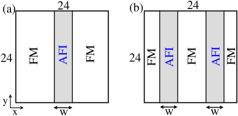
Two types of FM/AFI superlattices are shown schematically in Fig.1; denotes the width of the AFI spacer. Periodic boundary conditions in both directions ensures that the superlattice structures are composed of alternating FM and AFI layers. The type I superlattice is considered in the following discussions while results for the type II superlattice are discussed in the concluding paragraphs.
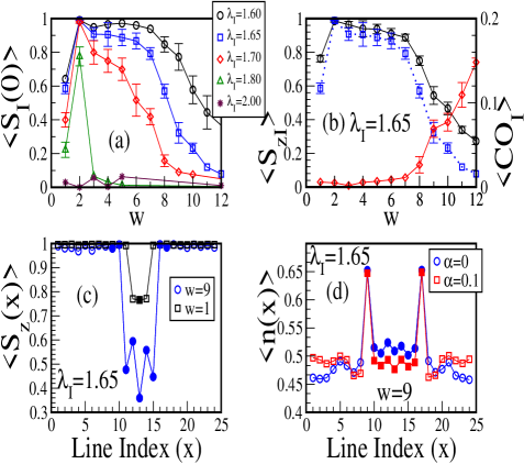
Different combinations of electron-phonon couplings (, ) are considered first in the absence of LRC intreractions . To start with we discuss the results for 1.65 (see Fig.2(a)), for which the ferromagnetic structure factor behaves non-monotonically with increasing AFI layer width, where = e and the angular bracket denotes the average over thermal equilibrium configurations combined with an additional average over ten different ‘samples’. The induced magnetization in the AFI layer is small for , nearly equal to 1 (all the t2g spins are fully ordered) for , and rapidly decreases for .
The averaged component of the t2g spins in the AFI layer for = 1.65 is similarly non-monotonic as as shown in Fig.2(b). We also calculate the local staggered charge order by = e where denotes lattice sites in the AFI layer with position . , shown in Fig.2(b), remains small for and starts to rise for . The decrease in the magnetization accompanied by the emerging charge order indicate that the AFI layer gradually returns to the bulk AFI state with increasing .
for different values also varies non-monotonically with increasing width of the AFI layer except for = 2.0. The induced magnetic moment for decreases more rapidly for larger electron-phonon coupling . The AFI layer recovers the AF, charge ordered state at a smaller width for larger . This is why it is possible to magnetize only 2 lines of the AFI layer for while for the induced magnetic moment remains very small in the AFI layer irrespective of its width.
In order to understand the non-monotonic behavior we specifically choose and for which is small. To start with we analyze the magnetization profile across the interface by calculating average magnetization for each line of the superlattice for transverse coordinate . , in Fig.2(c), decreases for = 11-15 for , in the center lines of the AFI layer, which implies that the induced ferromagnetic moment in the AFI layer is confined to the near vicinity of the interface. The relation between the induced magnetization and the line-averaged electron density becomes evident in Fig.2(d). for the interfacial line on the FM side, named as FM interfacial line, decreases while the AFI interfacial line increases from the initial electron density 0.5 to 0.65. The induced ferromagnetic moment for the lines = 9 and 17 is therefore due to the enhanced electron density and the spin bias from the ferromagnetic metal. In fact, for the parameters , , and the groundstate of the bulk system is a FM. The magnetization in the line = 10 (16) is induced by the fully magnetized line = 9 (17). The interfacial lines of the AFI layer are also magnetized for other values, except for which is discussed later. The spin bias from the ferromagnetic metal is important for the induction of a ferromagnetic moment in the AFI interfacial lines. The induced magnetization in the AFI layer is very small irrespective of the AFI layer width where the FM interfacial lines are magnetically disorderedkp-sl-prb .
The direction of electron transfer is from the FM to the AFI layer as anticipated earlier. Sufficiently far away from the interface the average electron density must return to the initial electron density , which however is not fully accomplished for and . But with the additional LRC interaction indeed gradually returns to the initial electron density (see Fig.2(d)). For the average electron densities are clearly higher (lower) in the FM (AFI) layers as compared to . In the FM/AFI superlattices, where the constituent FM and AFI manganites have the same initial electron density, the LRC interaction reduces the critical width, beyond which starts to decreasekp-sl-prb . Remarkably, at the FM interfacial lines is largely unaltered by the LRC interactions.
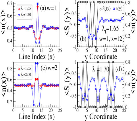
The line averaged for is also shown in Fig.2(c). But in contrast to the AFI layer width , in the FM interfacial line decreases for . The difference results from the decrease in the electron density for in the FM interfacial line as shown in Fig.3(a). The spin pattern in the interfacial line decomposes into FM and G-type AF regions. This is shown in Fig.3(b) which displays the averaged components of the t2g spins for each site of the FM interfacial line for one selected ’sample’.
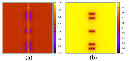
The averaged electron density at the FM interfacial line is smaller for as compared to as shown in Fig.3(a). For this reason the G-type AF regions in the FM interfacial line are more pronounced for (see Fig.3(d)). The electron densities and the components of the t2g spins at each site in the FM/AFI superlattice are shown in Fig.4 for . The magnetic and the electronic profile of both FM interfacial lines are similar to each other on both sides of the AFI line. The magnetic profile of the AFI line is tied to the profile of the FM interfacial lines while the electron density of the sites in the AFI layer is enhanced to 0.7.
With increasingly larger values of the magnetization of the FM interfacial line decreases due to the enhanced G-type correlations for . This establishes the crucial relation between the magnetization at the FM interfacial line and the induced magnetic moment in the AFI layer. This is in general true for any width . So the non-monotonic behavior of in Fig.2(a) implies that the FM interfacial line remains ferromagnetic for . For the decrease in the electron density in the FM interfacial line (see Fig.3(c), ) is very small as compared to , and these lines therefore remain ferromagnetic. For the electron density in the FM interfacial line decreases considerably except for . The electron density profile for and resembles the profile of and shown in Fig.3(c). This implies that the charge transfer across the interface from the FM to the AFI layer also varies non-monotonically similar to the induced magnetic moment in the AFI layer shown in Fig.2(a). The competition between FM and G-type AF spin patterns at the interface is controlled by the double-exchange energy gain due to the induced magnetic moment in the AFI layer. The magnetization of the FM interfacial layer remains ferromagnetic for , i.e. the large induced magnetic moment in the AFI layer removes the MDL.
At large electron-phonon couplings electrons are site-localized due to strong lattice distortions; this decreases the double-exchange energy gain from induced ferromagnetic moments which are hence absent in the AFI layer (see Fig.2(a)) irrespective of the AFI layer width. For this reason G-type spin patterns are more prominent at the FM interfacial lines and in the FM interfacial line decreases considerably (see e.g. Fig.3(c) for and ). These results suggest that also in FM/NMI superlattices local AF correlations may emerge in the FM interfacial line and the magnetization at the interface is wiped out originating in an MDL due to the decrease in the electron density at the interfacesun-NdGaO3-mdl ; bibes-lcmo-mdl .
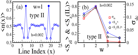
In the type I FM/AFI superlattices the spins in the FM leads are aligned in the same direction due to the periodic boundary conditions; this set up mimics the experimental situation in which the FM layers of the superlattice are aligned by an external magnetic field. Specifically we have designed the type II superlattice where two AFI layers instead of one are considered as shown in Fig.1(b) to represent more closely the experimental setup. The magnetizations in the left and the right FM layers are aligned parallel while the middle FM layer is free to choose its spin direction. A small external magnetic field is applied to align all the FM layers in the same direction. Fig.5(a) shows the line averaged vs. line index for , , and . In Fig.5(b), we plot the averaged in the AFI layers along with averaged component of the spins in the FM interfacial lines for the same magnetic field. The magnetization of the FM interfacial line follows a non-monotonic behavior similar to the induced magnetic moments in the AFI layer. The dc limit of the longitudinal conductivity , also displayed in Fig.5(b), as obtained from the Kubo-Greenwood formulamahan-book ; cond-ref , follows the same trend with increasing AFI layer width . It is the combination of the induced magnetic moment in the AFI layer and the magnetization of the FM interfacial lines which enhances the conductivity.
In the type II set up the TMR may be calculated by fixing the spins of the middle FM layer in the direction opposite to that of the left and right FM layers. However in the limit adopted here where the spins of the mobile eg electrons are perfectly aligned along the local spin direction the dc conductivity (resistivity) for this set up is zero (infinity). For this reason a quantitative calculation of TMR for different widths of the AFI layer is not presented here. In the experiments the resistivity is large but finite in the antiparallel configuration of the FM layers. The increase of the conductivity in the parallel configuration of the FM layers, shown in Fig.5(b) will necessarily enhance the TMR.
In conclusion, our 2D model calculations provide a framework to explain the origin of the MDL at the FM interface in FM/Insulator superlattices. The magnetization of the interfacial lines of the FM layers is determined by the amount of electron transfer from the FM interfacial lines to the AFI layer. The decrease in the magnetization of the FM interface, when joined with a NMI oxide is due to the decrease in the electron density at the interfacial lines as a result of the charge transfer across the interface. The amount of transferred charge is limited in a scenario for which instead AFI layers are sandwiched between FM layers, since inducing ferromagnetic moment in the AFI layer requires to control the charge transfer. But even in such a FM/AFI superlattices, the MDL is absent only for a specific range of AFI layer widths, because the induced magnetic moment in the AFI layer varies non-monotonically with the AFI layer widthmathur-lsmo-pcmo . The absence of the MDL in FM/AFI superlattices enhances the TMR. The MDL at the interface in an FM/NMI junction may be minimized by the insertion of an intervening AFI layer. In such a setup, the width of the AFI layer has to be chosen such that the AFI layer is maximally polarized along the direction of the magnetization in the FM layers due to charge transfer. Indeed the TMR is significantly enhanced in the engineered FM/NMI MTJs with an intervening AFI layerfm-afi-nmi-ref ; fm-afi-nmi-ref1 . The role of the MDL for different widths of the intervening AFI layer in these engineered MTJs deserves further investigation. We leave this as the subject for future work.
This work was supported by the DFG through TRR80.
References
- (1)