Pointing LISA-like gravitational wave detectors
Abstract
Space-based gravitational wave detectors based on the Laser Interferometer Space Antenna (LISA) design operate by synthesizing one or more interferometers from fringe velocity measurements generated by changes in the light travel time between three spacecraft in a special set of drag-free heliocentric orbits. These orbits determine the inclination of the synthesized interferometer with respect to the ecliptic plane. Once these spacecraft are placed in their orbits, the orientation of the interferometers at any future time is fixed by Kepler’s Laws based on the initial orientation of the spacecraft constellation, which may be freely chosen. Over the course of a full solar orbit, the initial orientation determines a set of locations on the sky were the detector has greatest sensitivity to gravitational waves as well as a set of locations where nulls in the detector response fall. By artful choice of the initial orientation, we can choose to optimize or suppress the antennas sensitivity to sources whose location may be known in advance (e.g., the Galactic Center or globular clusters).
1 Introduction
In the current effort to open the gravitational wave astronomy frontier, a space-based laser-interferometric gravitational wave detector operating in the 0.1 mHz to 100 mHz waveband is far and away the most promising marriage of technological capability and number and variety of strong sources. In its most studied form a space-based laser interferometric gravitational wave detector involves three free-flying sciencecraft — acting as the stations of an interferometer — inhabiting 1 AU circumsolar orbits arranged so that the sciencecraft form an equilateral triangle constellation, inclined to the ecliptic plane by , with arm lengths of several million km (Jennrich et al., 2011). Once set in their orbits the orientation of the interferometer with respect to the celestial sphere is determined by Kepler’s laws of motion; correspondingly, the initial orientation of the equilateral triangle in its plane affects the detector’s sensitivity to gravitational waves sources in different regions of the sky. In all present proposals only one of the sciencecraft is equipped to measure the relative velocity to both of the other two sciencecraft; so, only one interferometer can be synthesized (Jennrich et al., 2011; Baker et al., 2011a, b, c, d). Here we show how the freedom to choose the initial orientation of the sciencecraft constellation — and, thus, the orientation of the interferometer — affects the detector’s sensitivity to gravitational waves associated with sources in the direction of the Galactic Center.
Decher et al. (1980) first investigated the design aspects of a space-based, laser interferometric gravitational wave detector. The mission and detector they described quickly converged to the modern “LISA” concept that, in its most mature form, is described in several technical assessments performed for ESA (Danzmann et al., 2011; Jennrich et al., 2011).111“LISA” was the name adopted for a joint ESA-NASA mission: in the U.S. as part of NASA’s Beyond Einstein Program and in Europe as part of ESA’s Cosmic Vision 2015-2025 Program. While that mission was ended when NASA was unable to meet its commitments, missions based on the LISA design but rescaled for different cost-caps are being considered by both ESA and NASA (Baker et al., 2011a, b, c, d; Jennrich et al., 2011). Here we use the term “LISA” to refer to any space-based, laser-interferometric gravitational wave detector whose mission profile is similar to the former joint ESA-NASA mission that was ranked as a large space mission priority in (Committee for a Decadal Survey of Astronomy and Astrophysics & National Research Council, 2010).
In the modern LISA concept each of the three sciencecraft follow independent, circumsolar orbits that lead or lag Earth in its orbit by tens of degrees. Each sciencecraft hosts a freely floating reference mass (a “gravitational reference sensor”, or GRS) that it simultaneously shields from the thermal and particle space environment and tracks to ensure that the sciencecraft trajectory is as close to a free trajectory through space-time as technology allows. Modulated laser signals passed between the sciencecraft are used to measure the relative velocities of the three reference masses. Gravitational waves passing through the constellation lead to correlated disturbances in these relative velocity measurements.
The gravitational wave antenna that is synthesized from the relative velocity measurements of the three reference masses behaves like an interferometer with one sciencecraft acting as a beamsplitter and the other two acting as end-stations (Armstrong et al., 2003; Dhurandhar & Tinto, 2005). Like an interferometer its greatest sensitivity is to sources in the directions normal to the plane defined by the three sciencecraft. Also like an interferometer the antenna has four nulls — directions in which it is entirely insensitive to gravitational wave sources — that lie in the plane. The direction of these nulls is tied to the orientation of the sciencecraft in their plane. The requirement that the sciencecraft each travel freely through space yet maintain, over several orbital periods, the same relative configuration, strongly constrains the sciencecraft orbits (Folkner et al., 1997; Folkner, 2001; Dhurandhar et al., 2002, 2005), leading each null to trace-out a “figure-eight” pattern on the sky over the course of a year. Where these patterns appear on the sky is set by the initial orientation of the sciencecraft in their plane. Our purpose here is to demonstrate how the choice of initial constellation orientation affects the sensitivity of LISA concept detectors to the direction hosting the greatest number of gravitational wave sources: i.e., the Galactic Center.
Section 2 of this manuscript describes our sensitivity measure for a LISA concept gravitational wave antenna as it orbits Sol. Section 3 examines the sensitivity of a LISA concept mission to gravitational wave sources in the direction of Milky Way Galactic Center and some of the more important Milky Way globular clusters. We summarize our conclusions in Section4.
2 Sensitivity measure
We base our measure of LISA’s sensitivity to point gravitational wave sources on its low-frequency angular response. For our purposes the three LISA sciencecraft correspond to the beamsplitter and end-mirrors of a Michelson delay-line interferometer. Each sciencecraft is on an independent, 1 AU circumsolar orbit. These orbits are chosen so that the sciencecraft remain close to relative rest at the vertices of an equilateral triangle with km legs. We refer to the relative position of the sciencecraft as the constellation. Tidal forces on the constellation owing to Sol, the Earth-Moon system, Jupiter and Venus all act to distort this configuration. The LISA mission lifetime is bounded by an upper limit on the relative sciencecraft velocities. This bound will be exceeded well-before deviations in the constellation shape affect significantly the angular sensitivity of the interferometer. Correspondingly, it is conventional to treat the constellation as a rigid equilateral triangle whose center follows a Kepler orbit, in the ecliptic plane, about Sol. We follow this convention.
To evaluate LISA’s response consider a (TT-gauge) plane gravitational wave propagating in the direction through Minkowski space:
| (2-1) |
where and are the usual and wave polarization tensors,
| (2-2a) | ||||
| (2-2b) | ||||
| (2-2c) | ||||
In the low-frequency (small antenna) limit the response of the inferometer may be expressed
| (2-3a) | ||||
| where is the effective interferometer arm-length, the constellation location, | ||||
| (2-3b) | ||||
| (2-3c) | ||||
| and is the antenna projection tensor: | ||||
| (2-3d) | ||||
with and the unit vectors in the direction of the interferometer arms.
Our basic measure of LISA’s sensitivity is the quadrature sum of and ,
| (2-4) |
and its value integrated over a year-long observation and normalized so that its maximum value, over all , is unity:
| (2-5a) | ||||
| where | ||||
| (2-5b) | ||||
Note that the dependence of on is identical to the dependence on of the power signal-to-noise associated with a compact object binary system when averaged over the binary’s orientation.
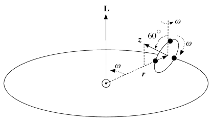
The time dependence of and is determined by the motion of the constellation as it orbits Sol. The special orbits that allow the constellation to maintain a relatively stable equilateral triangle configuration enforce upon the constellation a characteristic internal motion and orientation with respect to the constellation’s orbital plane. The orientation and motion is particularly simple when described in terms of the constellation plane’s orientation relative to its orbital plane about Sol, and the orientation of the constellation in the constellation’s plane. The sciencecraft orbits require that the constellation plane is always inclined relative to the ecliptic plane (i.e., the constellation’s orbital plane) with the constellation plane normal always in the plane defined by the constellation’s orbital radius vector and its orbital plane normal: i.e., the constellation plane precesses, in a positive sense, about the ecliptic plane normal with a one-year period. In addition to this precession, the constellation itself spins within its plane, also with a one-year period. Choosing the constellation plane normal’s direction to have a positive projection on the ecliptic plane normal the constellation spins in its plane with a negative sense. Figure 1 shows these three different motions — orbital, precessional, and spin — schematically.
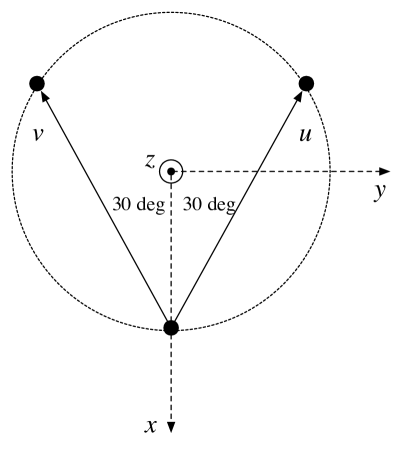
To evaluate and via Equations (2-3b)–(2-3c) we need to express , , and all in the same coordinate system. We choose to work in (heliocentric) ecliptic coordinates. To express and , the unit vectors in the direction of the interferometer arms, in ecliptic coordinates we first describe them in the constellation’s rest frame; next, we describe the rotations that relate ecliptic and constellation rest coordinates; and, finally, we express and in ecliptic coordinates via Equations 2-8. Figure 2 shows the constellation, the interferometer arms, and the constellation rest-frame coordinates that we use to describe the constellation’s gravitational wave response. In these coordinates and are
| (2-6a) | ||||
| (2-6b) | ||||
The convolution of the different rotations involved in describing the constellation’s motion is quite simply expressed in terms of quaternions. Introduce the usual quaternion basis , and , with
| (2-7) |
Associate the quaternion basis vectors with the basis vectors of a Cartesian coordinate system: i.e., associate with , with and with . Any vector may thus be regarded equally well as a quaternion or a Cartesian vector. It is then straightforward to show that the vector corresponding to the rotation of vector by angle about axis is equal to
| (2-8a) | ||||
| where | ||||
| (2-8b) | ||||
| (2-8c) | ||||
To describe the relation between ecliptic and constellation rest-frame coordinates first introduce the usual ecliptic longitude and latitude and the corresponing Cartesian coordinate vectors , and . Measure the constellation’s location in its orbit in terms of the position angle , measured from , with at . Finally, let denote the constellation plane orientation at . The quaternion that relates vector components in the constellation coordinate system to components in the ecliptic coordinate system may be written
| (2-9a) | ||||
| where orients the constellation in its plane, | ||||
| (2-9b) | ||||
| inclines the constellation plane relative to the ecliptic, | ||||
| (2-9c) | ||||
| and precesses the constellation plane about the ecliptic normal, | ||||
| (2-9d) | ||||
It remains to express the polarization tensors and in ecliptic coordinates. Let and identify the ecliptic longitude and latitude corresponding to the wave propagation direction (i.e., the source is in the direction). A suitable choice of polarization tensors and is then
| (2-10a) | ||||
| (2-10b) | ||||
| where | ||||
| (2-10c) | ||||
| (2-10d) | ||||
| for | ||||
| (2-10e) | ||||
| (2-10f) | ||||
| (2-10g) | ||||
3 Discussion
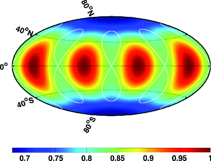
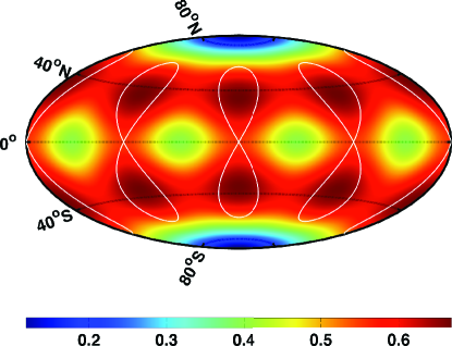
An interferometric detector has a null response to gravitational-wave sources in four different directions — all in the plane formed by the detector. When the light travel time along its arms is equal, as is the case for LISA, two of the nulls are in the direction and anti-direction of the bisector between the arms, while the other two nulls are at right angles to these directions: i.e., in the and directions in Figure 2. As the antenna orbits Sol these nulls trace out figure-8 patterns on the sky. The white curves in Figure 3 show, in ecliptic coordinates, the trace of these nulls over a full orbit overlaid on a colormap that shows our sensitivity measure (see Eq. 2-5).
Note that the ecliptic longitude is unlabeled in Figure 3. The ecliptic longitude of the traces of the nulls depend on the constellation’s initial orientation (see Eq. 2-9) at : i.e., rotating the constellation in its plane while leaving the plane’s location and orientation fixed shifts the null curves in ecliptic longitude by the same angle. It is the initial choice of constellation orientation that allows us to “point” LISA toward or away from any source that lies within of the ecliptic plane.
Although all but the closest extragalactic sources of gravitational radiation are likely to be distributed isotropically, Galactic sources — including the vast majority of close white dwarf binaries, by far the largest expected population of LISA sources — will be concentrated primarily in the direction of the Galactic Center and, secondarily, the Galactic plane. It is a fortunate coincidence that the Galactic Center lies nearly on the ecliptic plane and the Galactic Plane, like the LISA constellation plane, is inclined relative to the ecliptic plane: just those regions on the sky where the choice of gives us greatest control over LISA’s sensitivity. Referring to Figure 3, our initial choice of LISA constellation orienation can make a 17% difference in the constellation’s sensitivity toward the Galactic Center sources: i.e., to just those sources that dominate LISA’s signal. If we choose as our goal the study of these sources we can maximize LISA’s sensitivity to the Galactic Center direction; alternatively, if our goal is the detection and study of extragalactic sources we can choose LISA’s initial orientation to minimize our sensitivity to these (now confounding) sources, allowing LISA observations to “dig deeper” into the pool of extra-galactic sources.
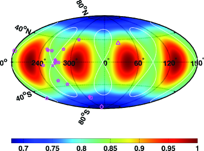
Now consider the binary choice of maximizing or minimizing LISA sensitivity to Galactic Center sources and ask what effect this choice has on the sensitivity to gravitational wave emitters associated with other localized and nearby objects: in particular, globular clusters within 5 kpc of Earth, the Large and Small Magellanic clouds, the Andromeda galaxy (M31), and the Virgo cluster. These objects are representative of typical hosts for halo and extragalactic populations of white-dwarf binaries, ultra compact binaries, and nearby extreme mass-ratio inspiral systems. Figure 4 and Table 1 summarize how minimizing or maximizing sensitivity to Galactic Center sources affects LISA’s sensitivity to gravitational wave emitters associated with these objects. Figure 4 plots the object locations, given in the first two columns of Table 1, together with the antenna nulls and sensitivity measure corresponding to an initial LISA orientation that suppresses the constellation’s response to Galactic Center sources. Both Magellanic clouds (diamond for the LMC, square for the SMC) and two globular clusters (47 Tuc and NGC 3201, both marked with stars) are sufficiently far south of the ecliptic that there is negligible change in the sensitivity for any constellation orientation. Most of the remaining globular clusters (all marked with stars) are close enough to the Galactic Center that LISA’s sensitivity to sources within them varies together with sensitivity to the Galactic Center. Only for the globular cluster M71 and the Andromeda galaxy (M31) is the constellations’s sensitivity relatively high when it is relatively low for Galactic Center sources. The final column of Table 1 quantifies these observations, providing for each object the ratio , where () is the sensitivity measure when the constellation’s orientation is chosen to (maximize (minimize) its sensitivty to Galactic Center sources.
| Object | Lon | Lat | Sources | |
|---|---|---|---|---|
| Gal. Cen. | 266.85172 | -5.6076736 | DWD, COB | 0.84 |
| Virgo Cluster | 181.04266 | 14.333893 | COB, EMRI | 0.82 |
| LMC | 312.50989 | -85.351425 | COB | 1.00 |
| SMC | 312.08823 | -64.605469 | COB | 0.99 |
| Androm. Gal. (M31) | 27.849274 | 33.349022 | COB, EMRI | 1.04 |
| NGC104 (47Tuc) | 311.25247 | -62.352768 | DWD, COB | 1.03 |
| NGC3201 | 181.36612 | -51.539581 | DWD, COB | 0.97 |
| NGC6121 (M4) | 248.48676 | -4.8687668 | DWD, COB | 0.96 |
| NGC6218 (M12) | 250.57292 | 20.272308 | DWD, COB | 0.97 |
| NGC6259 (M10) | 253.45894 | 18.441391 | DWD, COB | 0.94 |
| NGC6366 | 261.54391 | 18.122971 | DWD, COB | 0.88 |
| NGC6397 | 266.69220 | -30.290436 | DWD, COB | 0.90 |
| NGC6544 | 271.66437 | -1.5686417 | DWD, COB | 0.83 |
| 2MS_GC01 | 271.97073 | 3.5952682 | DWD, COB | 0.83 |
| 2MS_GC02 | 272.24817 | 2.6416550 | DWD, COB | 0.83 |
| Terzan12 | 272.82751 | 0.66725922 | DWD, COB | 0.84 |
| NGC6656 (M22) | 278.31403 | -0.72771454 | DWD, COB | 0.86 |
| GLIMPSE01 | 283.12085 | 21.387779 | DWD, COB | 0.91 |
| NGC6752 | 281.02106 | -37.221313 | DWD, COB | 0.95 |
| NGC6838 (M71) | 305.34909 | 38.792225 | DWD, COB | 1.05 |
Now turn attention to the variation in LISA sensitivity to fixed sources over the course of a year. As the constellation rotates in its plane is modulated for all sources but those in the direction of the ecliptic poles. For sources within of the ecliptic plane there will be choices of orientation that lead an antenna null to pass over the source at least once per year, corresponding to 100% modulation of antenna’s response to the incident waves. Figure 5 summarizes the modulation of the response as the fractional root-mean-square variation of from its mean value over an orbital period: i.e.,
| (3-1) |
For sources at ecliptic latitudes the modulation is greater than % regardless of the initial constellation orientation. Referring to Table 1 this includes three of the nearest globular clusters (NGC3201, NGC6752 and NGC6838). For sources with ecliptic latitude the degree of modulation varies significantly with the initial constellation orientation: for sources on the ecliptic equator it can be varied between and %.Only for sources near the ecliptic poles () will the modulation ever be small (%).
The modulation of LISA’s sensitivity in a given direction provides another means of “tuning” LISA’s sensitivity to different sources. It has often been remarked that the number of low-frequency sources in the direction of the Galactic Center is sufficiently great that their cacophony may limit our ability to observe other low-frequency sources elsewhere on the sky (Bender et al., 1996; Kosenko & Postnov, 1998). Taking advantage of our ability to point LISA by choosing its initial orientation, we can arrange for the antenna nulls pass over or close to the Galactic Center twice per year. During these periods LISA will largely insensitive to Galactic Center sources while remaining sensitive to sources at moderate to high ecliptic latitudes, and low ecliptic latitudes at longitudes and from the Galactic Center. This includes most of the sources identified in Table 1.
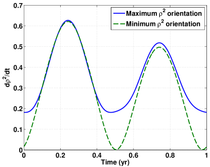
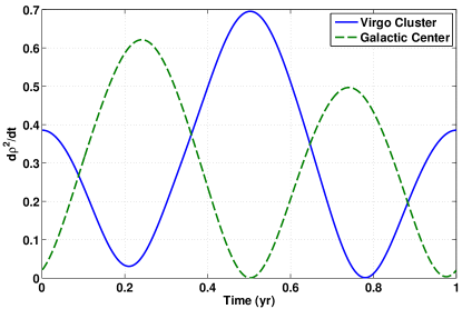
To illustrate, Figure 6 shows how the modulation in sensitivity varies over the course of a year for Galactic Center direction sources when LISA’s initial orientation is chosen to maximize or minimize its sensitivity in this direction. While the peak sensitivity over the course of a year varies only slightly, the minimium sensitivity can be sent to zero. Figure 7 shows LISA’s sensitivity to sources in the direction of the Virgo Cluster and the Galactic Center when LISA’s orientation is chosen to so that an antenna null passes over the Galactic Center twice per year. For this orientation LISA’s sensitivity to sources in the direction of the Galactic Center vanishes just when its sensitivity to sources in the direction of the Virgo Cluster is greatest, and vice versa. Thus, by appropriate pointing of LISA we can mitigate significantly any interference that Galactic close white dwarf binaries have in the detection of extra-galactic sources.
4 Conclusions
The LISA sciencecraft form what is effectively an interferometric gravitational wave antenna. Such an antenna has four nulls: i.e., directions in which it is entirely insensitive to incident gravitational waves. As the sciencecraft proceed in their special orbits the antenna rotates and precesses, leading the nulls to trace-out four figure-8 pattens on the sky. The choice of initial constellation orientation can be chosen to ensure that a null traces over, or avoids, any fixed sky location within of the ecliptic plane. Sources in this zone include the Galactic Center, the Virgo Cluster, and the nearest Galactic globular clusters. By choice of the initial constellation orientation LISA may thus be pointed toward or away from any of these sources, with significant consequences for the success of its science mission. In the case of sources in the direction of the Galactic Center this freedom amounts to a 17% difference in the power signal-to-noise accumulated over a year’s observation (averaged over all source orientations).
As important as the variation in the annual signal-to-noise is the variation in the sensitivity throughout the sciencecraft constellation’s annual orbital period. The relative location of the Galactic Center and the Virgo Cluster is such that we may choose a null to cover the Galactic Center during just those times when the antenna’s sensitivity to the Virgo Cluster is greatest. Thus, we can arrange our orbits to suppress the confusion noise associated with the large number of Galactic white dwarf binaries at just those times when our sensitivity to Virgo Cluster sources is greatest.
The choice of initial constellation orientation need not affect the mission cost. The dominant cost to the mission associated with a choice of initial constellation orientation is that required to launch the mass in fuel needed to move the sciencecraft from Earth to their initial orbital stations. Viewed with respect to Earth there is a constellation orientation that requires minimum fuel mass to reach. By appropriate choice of launch date we can make this cost-preferred Earth-relative configuration correspond to any desired ecliptic coordinate relative orientation.
How to best take advantage of the ability to point a LISA-like gravitational wave antenna requires the kind of judgements that are only possible in the context of the mission science goals: e.g., is the mission’s principal science goal the study of Galactic sources, extra-galactic sources, or something different still? Here we have demonstrated that the mission profile includes a heretofore unrealized freedom — the ability to point the antenna toward or away from sources within of the ecliptic plane — and have given but one example of how choices in pointing can affect sensitivity to multiple sources.
References
- Armstrong et al. (2003) Armstrong, J. W., Estabrook, F. B., & Tinto, M. 2003, Class. Quantum Grav., 20, 283
- Baker et al. (2011a) Baker, J., Benacquista, M., Berti, E., Brinker, E., Buchman, S., Camp, J., Cornish, N., Cutler, C., de Vine, G., Finn, L. S., Gair, J., Gallagher, R. J., Hellings, R., Hughes, S., Klipstein, W., Lang, R., Larson, S., Littenberg, T., Livas, J., McKenzie, K., McWilliams, S., Mueller, G., Norman, K., Spero, R., Stebbins, R., Thorpe, J., Vallisneri, M., Welter, G., & Ziemer, J. 2011a, SGO High: A LISA-Like Concept for the Space-based Gravitational-wave Observatory (SGO) at a High Cost-Point, Tech. rep., NASA Goddard SpaceFlight Center
- Baker et al. (2011b) —. 2011b, SGO Low: A LISA-Like Concept for the Space-based Gravitational-wave Observatory (SGO) at a Low Price-Point, Tech. rep., NASA Goddard SpaceFlight Center
- Baker et al. (2011c) —. 2011c, SGO Lowest: A LISA-Like Concept for the Space-based Gravitational-wave Observatory (SGO) at the Lowest Cost-Point, Tech. rep., NASA Goddard SpaceFlight Center
- Baker et al. (2011d) —. 2011d, SGO Mid: A LISA-Like Concept for the Space-based Gravitational-wave Observatory (SGO) at a Middle Price-Point, Tech. rep., NASA Goddard SpaceFlight Center
- Bender et al. (1996) Bender, P., Ciufolini, I., Danzmann, K., Folkner, W., Hough, J., Robertson, D., Rüdiger, A., Sanford, M., Schilling, R., Schutz, B., Stebbins, R., Sumner, T., Touboul, P., Vitale, S., Ward, H., Winkler, W., Cornelisse, J., Hechler, F., Jafry, Y., & Reinhanrd, R. 1996, LISA. Laser Interferometer Space Antenna for the detecion and observaiton of gravitational waves, Tech. rep., Max-Planck-Institut für Quantenoptik, Hans-Kopfermann-Str. 10, D-85748 Garching, mPQ 208
- Committee for a Decadal Survey of Astronomy and Astrophysics & National Research Council (2010) Committee for a Decadal Survey of Astronomy and Astrophysics & National Research Council. 2010 (National Academies Press)
- Danzmann et al. (2011) Danzmann, K., Prince, T. A., Binetruy, P., Bender, P., Buchman, S., Centrella, J., Cerdonio, M., Cornish, N., Cruise, M., Cutler, C. J., Finn, L. S., Gundlach, J., Hogan, C., Hough, J., Hughes, S. A., Jennrich, O., Jetzer, P., Lobo, A., Madau, P., Mellier, Y., Phinney, S., Richstone, D. O., Schutz, B., Stebbins, R., Sumner, T., Thorne, K., Vinet, J.-Y., & Vitale, S. 2011, LISA: Unveiling a hidden Universe, Tech. Rep. ESA/SRE(2011)3, European Space Agency
- Decher et al. (1980) Decher, R., Randall, J. L., Bender, P. L., & Faller, J. E. 1980, in Presented at the Society of Photo-Optical Instrumentation Engineers (SPIE) Conference, Vol. 228, Society of Photo-Optical Instrumentation Engineers (SPIE) Conference Series, ed. W. J. C. Jr., 149–153
- Dhurandhar et al. (2005) Dhurandhar, S. V., Nayak, K. R., Koshti, S., & Vinet, J.-Y. 2005, Class. Quantum Grav., 22, 481
- Dhurandhar et al. (2002) Dhurandhar, S. V., Nayak, K. R., & Vinet, J.-Y. 2002, Phys. Rev. D, 65, 024015
- Dhurandhar & Tinto (2005) Dhurandhar, S. V. & Tinto, M. 2005, Living Reviews in Relativity, 8, 4
- Folkner (2001) Folkner, W. M. 2001, Class. Quantum Grav., 18, 4053
- Folkner et al. (1997) Folkner, W. M., Hechler, F., Sweetser, T. H., Vincent, M. A., & Bender, P. L. 1997, Class. Quantum Grav., 14, 1405
- Jennrich et al. (2011) Jennrich, O., Binetruy, P., Colpi, M., Danzmann, K., Jetzer, P., Lobo, A., Nelemans, G., Schutz, B., Stebbins, R., Sumner, T., Vitale, S., & Ward, H. 2011, NGO. Revealing a hidden Universe: opening a new chapter of discovery, Tech. Rep. ESA/SRE(2011)19
- Kosenko & Postnov (1998) Kosenko, D. I. & Postnov, K. A. 1998, A&A, 336, 786