The phase shift induced by a single atom in free space
Abstract
In this article we theoretically study the phase shift a single atom imprints onto a coherent state light beam in free space. The calculations are performed in a semiclassical framework. The key parameters governing the interaction and thus the measurable phase shift are the solid angle from which the light is focused onto the atom and the overlap of the incident radiation with the atomic dipole radiation pattern. The analysis includes saturation effects and discusses the associated Kerr-type non-linearity of a single atom.
I Introduction
The interaction of light and single atoms in free space has received a considerable amount of interest over the past years, see Ref. Leuchs and Sondermann (2013) for an overview of recent achievements in this field. Here, the term free space is used to describe a situation in which the atom interacts with the whole continuum of the free-space field modes and has also the characteristic free-space spatial emission properties. Besides other phenomena, the phase shift imprinted by a single quantum system onto a coherent beam has been studied in prior experiments Aljunid et al. (2009); Pototschnig et al. (2011); Hétet et al. (2012). The reported phase shifts amount to about 1∘ using a single neutral atom Aljunid et al. (2009) and 3∘ for a single molecule Pototschnig et al. (2011). Phase shifts of about 0.3∘ have been achieved recently for a single ion Hétet et al. (2012). For the sake of simplicity, all kinds of quantum systems will be denoted by the term ’atom’ throughout this paper.
The maximum phase shift observed for a free-space setup is still an order of magnitude below the values achieved with cavity quantum electrodynamics setups Turchette et al. (1995); Fushman et al. (2008); Young et al. (2011), but a phase shift close to the maximum possible value of 180∘ has not been observed in either system. Dispersive interaction has also been studied for an atomic ensemble trapped in the evanescent field of a nano fibre Dawkins et al. (2011). However, the deduced phase shift per single atom does not exceed the values measured so far in a free-space setup.
The typical phase-shift setup in free space can be simplified to the scheme shown in Fig. 1. The incident electromagnetic field mode is focused onto the atom by a focusing device, e.g. a large numerical aperture lens Aljunid et al. (2009); Pototschnig et al. (2011); Hétet et al. (2012) or a parabolic mirror Sondermann et al. (2007). Depending on the electric field strength acting upon the atom, the atom scatters a certain amount of dipole radiation which is phase-shifted with respect to the incident field. The phase of the scattered field is determined solely by the detuning of the incident light from the atomic resonance. The scattered radiation as well as the re-diverging incident field are both collected by the same optical element. This can be a second lens Aljunid et al. (2009); Hétet et al. (2012) or the focusing device itself. The latter is the case e.g. in Ref. Pototschnig et al. (2011), where a reflective element retro-reflects the incident radiation towards the focusing lens, or when using a deep parabolic mirror as envisaged earlier Sondermann et al. (2007); Lindlein et al. (2007).
After collection, scattered and incident radiation are processed in a phase measuring setup. This may be a Mach-Zehnder interferometer Aljunid et al. (2009), a heterodyning setup Pototschnig et al. (2011) or a scheme utilizing polarization degrees of freedom Hétet et al. (2012). As part of the phase measuring setup the scattered and re-collimated incident radiation are focused onto some detector where they interfere. From this it is clear that the overall overlap of the scattered radiation with the incident one plays a decisive role in determining the measurable phase shift, see also Ref. Aljunid et al. (2009). Moreover, the amount of coherently scattered light determines the impact of the phase of the scattered light onto the phase of the total field, i.e. the superposition of scattered field and incident field.

Theoretical treatments can be found in several publications. In Ref. Aljunid et al. (2009) the central parameter governing the phase of the total field is the so called scattering ratio, i.e. the ratio of scattered power to the incident power. This parameter includes the overlap of the incident field with the dipole field radiated by the atom. The scattering ratio can reach a value of two when focusing from half solid angle Zumofen et al. (2008); Tey et al. (2009), which is the upper limit considered in Ref. Aljunid et al. (2009) leading to a maximum phase shift approaching 90∘ for arbitrarily small but non-zero detunings. This is in accordance with the findings of Ref. Pototschnig et al. (2011) where the same maximum phase shift is predicted. There, a single overlap parameter is used to account for the focusing geometry as well as various aspects related to the use of a molecule. Nevertheless, phase shifts of more than 90∘ are possible. This is already evident from Eq. 26 of Ref. Zumofen et al. (2009): When considering a dipole wave incident from full solid angle, which corresponds to a semi-aperture angle in the nomenclature of Ref. Zumofen et al. (2009), one finds a phase shift of 180∘ on resonance. The same result is obtained when using the formulas of Ref. Aljunid et al. (2009) and calculating the scattering ratio for arbitrary solid angle, including the full solid angle case Leuchs and Sondermann (2013).
Another aspect is the influence of saturation of the atomic transition on the achievable phase shift. This aspect has been treated in the calculations of Ref. Pototschnig et al. (2011), where also a corresponding measurement has been performed, as well as by van Enk van Enk (2004). Although the latter paper is not explicitly devoted to the phase shift problem, the results reported here and elsewhere can be obtained by calculating the argument of Eq. 26 of Ref. van Enk (2004), using Eq. 41 of the same reference. There, the treatment is fully quantum-mechanical. However, also Ref. van Enk (2004) quantifies the similarity of the incident wave with a dipole mode by using a single parameter, which is inconvenient when modelling real experiments. The nonlinear phase shift induced onto a pulse containing more than one photon has been derived in Ref. Koshino (2008), where perfect coupling of atom and light field has been assumed implicitly. Consequently, the influence of the key parameters discussed here has not been treated.
In this paper, we present a discussion of the phase shift induced by a single atom in free space accounting for all of the above effects in an explicit way. Section II comprises the derivation of a formula for the phase shift, followed by the treatment of some examples in Sec. III. Finally, in Sec. IV the inclusion of saturation effects is used to derive a formula for the phase shift that is reminiscent of the Kerr effect found in other non-linear optical media.
II Derivation of the phase shift
We consider a two-level atom with upper level and lower level . It is located at the origin of the coordinate system. The atom is illuminated by a weak classical field of frequency and amplitude at the place of the atom. We take to be real. Thus, the relative phase of the field at the place of the atom is zero. Furthermore, is the amplitude of the field component parallel to the atomic dipole.
The expectation value of the positive frequency part of the electric field which is scattered by the atom is given by Scully and Zubairy (1997)
| (1) |
where and are the atomic transition frequency and the dipole matrix element (taken to be real), respectively, is the angle between the quantization axis and the point and is the atomic lowering operator. The expectation value of the lowering operator is given by Scully and Zubairy (1997) with being the density matrix element describing the polarization of the atom.
In the steady state, we have
| (2) |
with the spontaneous emission rate , the Rabi frequency , the detuning and the density matrix element gives the probability to find the atom in the upper state. The steady state solution of the latter is given by
| (3) |
which leads to
| (4) |
Thus, the scattered field amplitude is
| (5) |
The phase of the scattered field is hence given by
| (6) |
For a wave of power incident onto the atom the field amplitude parallel to the atomic dipole is given by Sondermann et al. (2008)
| (7) |
with . is the effective solid angle over which the incident field extends calculated weighting by the atomic dipole characteristics. It has a maximum value of . is the overlap of the incident field with the field emitted by the atomic dipole, calculated only in the region covered by the incident light. Next, we insert this expression for into the definition of the Rabi frequency, approximating . Plugging the result into Eq. 5 and integrating over the full solid angle we arrive at the scattered power
| (8) |
The last term in the sum of the the denominator is the saturation parameter on resonance .
For the sake of simplicity we normalize the solid angle to its maximum value, , which results in . Furthermore, the saturation parameter at non-zero detuning is . This leads to
| (9) |
Now, we have all ingredients at hand to calculate the phase of the field resulting from the superposition of the incident field and the scattered field. However, one has to distinguish two scenarios. The first one is a symmetric setup in the sense that the re-diverging incident field is collected with optics covering the same amount of solid angle as for focusing. Furthermore, the spatial radiation pattern of the incident light after re-collimation is identical to the one before focusing. This scenario is the one occurring in Refs. Aljunid et al. (2009); Pototschnig et al. (2011); Hétet et al. (2012). In an asymmetric setup, the optics used for collection/re-collimation may cover a different fraction of the solid angle than the one used for focusing, as also treated e.g. in Ref. Zumofen et al. (2008) for the extinction of a coherent beam. Another example for an asymmetric setup is the usage of different types of optics for focusing and collection, respectively Erik W. Streed et al. (2012); Jechow et al. (2013). Also every finite size parabolic mirror constitutes an asymmetric setup as outlined in more detail below.
II.1 Symmetric case
First, we have to account for the fact that only the part of the scattered field emitted into the solid angle cone of the transmitted incident field has to be considered. The power of this fraction is
| (10) |
The amplitude of the corresponding field mode is . Taking the phase of the scattered field into account yields . Furthermore, we have . We also have to account for the Gouy phase shift of that the transmitted wave experiences while re-diverging from the location of the atom Tyc (2012); Zumofen et al. (2008); Pototschnig et al. (2011); Aljunid et al. (2009). We do this by . Furthermore, only the part of the scattered wave that overlaps with the transmitted incident wave can interfere with it. Moreover, only the coherent part of the scattered light will interfere with the incident light Wrigge et al. (2008). The coherently scattered power fraction is given by Meschede (2005). We take this into account by writing
| (11) |
The phase of the coherent superposition of incident and scattered field can then be expressed as Aljunid et al. (2009). This leads to
| (12) |
With and we finally arrive at
| (13) | ||||
II.2 Asymmetric case
We now treat the asymmetric case. Using optics of different aperture for focusing and re-collimation results in an dipole weighted solid angle covered by the re-collimation optics . Thus Eq. 10 changes to
| (14) |
and we write with . A further consequence of such a scenario is that the overlap parameter , calculated only for the part of the solid angle used for focusing, may change for the re-collimation optics. Hence, for the part of the scattered light interfering with the incident light we have
| (15) |
Last but not least the case induces a power loss to the re-collimated incident beam. We account for this by introducing the parameter with . When calculating the -function, we now write .
With these modifications we arrive at the phase shift for the asymmetric, i.e. general case:
| (16) | ||||
III Examples
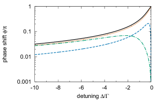
The results of some example calculations are given in Fig. 2, starting the discussion with the symmetric case. Since the phase shift just changes sign when the detuning does, only values for are plotted. The solid line depicts the case that results in the maximum possible phase shift at any detuning: focusing from full solid angle with a dipolar radiation pattern and a negligible saturation parameter.
The dashed line depicts the case when focusing from 38% of the solid angle weighted with the radiation pattern of a linear dipole oriented perpendicular to the optical axis. The solid angle fraction corresponds to the one covered by a microscope objective with a numerical aperture of NA=0.95. Again, we assume perfect mode overlap and negligible saturation.
Next, we treat an example for the asymmetric case. The dotted line corresponds to the experimental setup described in Refs. Sondermann et al. (2007); Golla et al. (2012) and a low but non-negligible saturation parameter. The setup consists of a parabolic mirror covering almost the entire solid angle, described by a parameter . As incident light field a radially polarized doughnut mode is considered. Such a mode is expected to couple efficiently to an atom with a linear dipole transition located at the mirror’s focus. A doughnut mode with an overlap parameter of has been achieved recently in experiments Golla et al. (2012). The dash-dotted line shows the phase shift for the same setup and strong saturation of the atom.
However, using a parabolic mirror brings some intricate details that necessitate the use of Eq. 16. Any ray propagating along the optical axis of the parabola which enters the mirror at a distance to the optical axis leaves the mirror at a distance with the focal length of the parabolic mirror Leuchs et al. (2008). This has the following consequences: For a finite parabolic mirror, the change entails that rays entering the mirror close to the optical axis do not hit the parabolic surface a second time and are not re-collimated. This results in a smaller effective solid angle for the re-collimated incident light and a re-collimated power-fraction . Furthermore, a parabolic mirror reshapes the radiation pattern of the incident beam. That is, after re-collimation by the parabolic mirror the transmitted incident beam has another overlap with the dipole mode than upon focusing onto the ion. In the present example, we account for all these effects by setting , , and .
Performing the calculations for the same setup using Eq. 13 for the symmetric case, i.e. setting , and , leads to larger phase shifts. But the deviations are so small, on the order of 1.5%, that Eq. 13 will be used in the remainder of this paper for the sake of simplicity. Nevertheless, one can construct realistic examples in which the deviation is more pronounced.
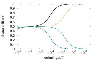
In what follows, we examine the phase shift close to resonance in more detail. For arbitrary and the phase shift on resonance is determined by the sign of the real part of the argument of the -function in Eq. 13:
| (17) |
In other words, the solid angle fraction must be larger than for observing a non-zero phase shift on resonance: Illumination has to occur from more than half the solid angle (see also Ref. Leuchs and Sondermann (2013)). However, even for a low or a large saturation parameter may result in zero phase shift. Figure 3 illustrates this discussion in a phase space picture.

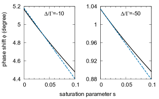
The change of the phase shift at from to zero occurs in an abrupt manner, i.e. the phase shift depends nonlinearly on the parameter combination . This is illustrated in Fig. 4 in more detail for detunings . The first example (solid line and dashed line) with the change of from slightly below to slightly above half solid angle may seem unrealistic. However, this case is realizable by using a parabolic mirror covering almost the entire solid angle and restricting the solid angle cone of the incident light to a fraction of the mirror surface corresponding to the values given above.
We conclude this section noting that it is obvious from Eqs. 17 and Fig. 3 that the overall phase shift is not determined by the atom but rather by the properties of the incident field and the set-up. No matter how large the coupling efficiency is in dependence of and Leuchs and Sondermann (2013); Golla et al. (2012), the phase of the light scattered coherently by the atom is fixed for a given detuning. This phase lag has been examined recently by a background subtraction technique Jechow et al. (2013) in an experimental regime of low coupling efficiency, i.e. exciting the atom from small solid angle. The better the coupling efficiency and the lower the saturation parameter, the larger is the amount of light scattered coherently into the mode of the incident field. This amount determines the phase of the superposition of incident and scattered field.
IV Intensity dependent phase shift
The examples presented in Figs. 2 and 4 already demonstrated that the phase shift induced by a single atom is strongly influenced by the intensity of the light driving the atom. In what follows, the phase shift derived above is put into a shape reminiscent of the typical formulas used to describe the optical Kerr effect. One way of describing this effect is to write the refractive index as Maker et al. (1964); Chiao et al. (1964); Boyd (1992)
| (18) |
where is the weak-field refractive index and describes the change of refractive index due to the intensity of the optical field. Corresponding more detailed expressions can be found for an ensemble of two-level atoms in free space e.g. in Ref. Boyd (1992) and e.g. in Ref. Hilico et al. (1992) for an an atomic ensemble in a cavity. To arrive at a similar expression in the scenario treated here requires several approximations.
In order to have an interaction that is predominantly dispersive, we assume a saturation parameter . In other words, the atom is not excited on average and the light is scattered coherently by the atom. The condition of low saturation is met easiest at large detunings. Therefore, we assume . This includes the case for which one finds that and hence . In other words, we can rewrite Eq. 13 as
| (19) |
Furthermore, the large detuning approximation allows to replace the function by its argument yielding
| (20) |
A Taylor expansion of the above equation around finally yields a Kerr-type expression reading
| (21) | |||||
V Concluding remarks
As outlined above, the phase shift induced on the exciting field by a single atom in free space is maximized by coupling the incident light to the atom from full solid angle. In this case, the phase shifts observed for large detunings are still of considerable magnitude. As evident from Fig. 5, the phase shift observed at 50 linewidths detuning is on the order of the ones reported for low detuning in previous experiments using free space setups. This suggests that a single atom in free space might be a good candidate for the realization of a quantum repeater scheme based on dispersive light-matter interaction. Such a scheme has been proposed by van Loock et al. for cavity based setups van Loock et al. (2006). When realizing such a system one has to balance all parameters carefully. For example, the induced phase shift should exceed the uncertainty of the phase of the incident coherent state, which is given by the inverse of the square root of the state’s amplitude if the latter is sufficiently large. Thus, on might be tempted to improve the performance by using coherent states of larger amplitude. But this in turn results in a larger saturation parameter and a reduction of the imprinted phase shift, unless the temporal width of the incident pulse is increased as well to maintain constant incident power. On the other hand, the pulse duration affects the success rate of the repeater scheme. This brief discussion highlights that a detailed assessment of all parameters using a free-space setup is desirable. However, this is beyond the scope of the present paper and subject of future work.
Acknowledgements.
The authors acknowledge M. Bader, R. Maiwald and M. Fischer for useful comments on the manuscript.References
- Leuchs and Sondermann (2013) G. Leuchs and M. Sondermann, Journal of Modern Optics 60, 36 (2013).
- Aljunid et al. (2009) S. A. Aljunid, M. K. Tey, B. Chng, T. Liew, G. Maslennikov, V. Scarani, and C. Kurtsiefer, Physical Review Letters 103, 153601 (2009).
- Pototschnig et al. (2011) M. Pototschnig, Y. Chassagneux, J. Hwang, G. Zumofen, A. Renn, and V. Sandoghdar, Phys. Rev. Lett. 107, 063001 (2011).
- Hétet et al. (2012) G. Hétet, L. Slodička, N. Röck, and R. Blatt, arXiv:1212.0810 (2012).
- Turchette et al. (1995) Q. A. Turchette, C. J. Hood, W. Lange, H. Mabuchi, and H. J. Kimble, Phys. Rev. Lett. 75, 4710 (1995).
- Fushman et al. (2008) I. Fushman, D. Englund, A. Faraon, N. Stoltz, P. Petroff, and J. Vučković, Science 320, 769 (2008).
- Young et al. (2011) A. B. Young, R. Oulton, C. Y. Hu, A. C. T. Thijssen, C. Schneider, S. Reitzenstein, M. Kamp, S. Höfling, L. Worschech, A. Forchel, et al., Phys. Rev. A 84, 011803 (2011).
- Dawkins et al. (2011) S. T. Dawkins, R. Mitsch, D. Reitz, E. Vetsch, and A. Rauschenbeutel, Phys. Rev. Lett. 107, 243601 (2011).
- Sondermann et al. (2007) M. Sondermann, R. Maiwald, H. Konermann, N. Lindlein, U. Peschel, and G. Leuchs, Appl. Phys. B 89, 489 (2007).
- Lindlein et al. (2007) N. Lindlein, R. Maiwald, H. Konermann, M. Sondermann, U. Peschel, and G. Leuchs, Laser Physics 17, 927 (2007).
- Zumofen et al. (2008) G. Zumofen, N. M. Mojarad, V. Sandoghdar, and M. Agio, Phys. Rev. Lett. 101, 180404 (2008).
- Tey et al. (2009) M. K. Tey, G. Maslennikov, T. C. H. Liew, S. A. Aljunid, F. Huber, B. Chng, Z. Chen, V. Scarani, and C. Kurtsiefer, New Journal of Physics 11, 043011 (2009).
- Zumofen et al. (2009) G. Zumofen, N. M. Mojarad, and M. Agio, Nuovo Cimento C 31, 475 (2009).
- van Enk (2004) S. J. van Enk, Phys. Rev. A 69, 043813 (2004).
- Koshino (2008) K. Koshino, Phys. Rev. A 78, 023820 (2008).
- Scully and Zubairy (1997) M. O. Scully and M. S. Zubairy, Quantum Optics (Cambridge University Press, Cambridge, 1997).
- Sondermann et al. (2008) M. Sondermann, N. Lindlein, and G. Leuchs, arXiv:0811.2098 [physics.optics] (2008).
- Erik W. Streed et al. (2012) Erik W. Streed, Andreas Jechow, Benjamin G. Norton, and David Kielpinski, Nature Communications 3, 933 (2012).
- Jechow et al. (2013) A. Jechow, B. G. Norton, S. Händel, V. Blūms, E. W. Streed, and D. Kielpinski, Phys. Rev. Lett. 110, 113605 (2013).
- Tyc (2012) T. Tyc, Opt. Lett. 37, 924 (2012).
- Wrigge et al. (2008) G. Wrigge, I. Gerhardt, J. Hwang, G. Zumofen, and V. Sandoghdar, Nature Physics 4, 60 (2008).
- Meschede (2005) D. Meschede, Optik, Licht und Laser (Teubner, Wiesbaden, 2005).
- Golla et al. (2012) A. Golla, B. Chalopin, M. Bader, I. Harder, K. Mantel, R. Maiwald, N. Lindlein, M. Sondermann, and G. Leuchs, Eur. Phys. J. D 66, 190 (2012).
- Leuchs et al. (2008) G. Leuchs, K. Mantel, A. Berger, H. Konermann, M. Sondermann, U. Peschel, N. Lindlein, and J. Schwider, Applied Optics 47, 5570 (2008).
- Maker et al. (1964) P. D. Maker, R. W. Terhune, and C. M. Savage, Phys. Rev. Lett. 12, 507 (1964).
- Chiao et al. (1964) R. Y. Chiao, E. Garmire, and C. H. Townes, Phys. Rev. Lett. 13, 479 (1964).
- Boyd (1992) R. W. Boyd, Nonlinear optics (Academic Press, 1992).
- Hilico et al. (1992) L. Hilico, C. Fabre, S. Reynaud, and E. Giacobino, Phys. Rev. A 46, 4397 (1992).
- van Loock et al. (2006) P. van Loock, T. D. Ladd, K. Sanaka, F. Yamaguchi, K. Nemoto, W. J. Munro, and Y. Yamamoto, Phys. Rev. Lett. 96, 240501 (2006).