The effect of gravity on the stability of an evaporating dichloromethane liquid film
Abstract
Zero gravity evaporation of a Dicholoromethane (DCM) liquid film is explored. The resulting film dynamics are presented and a criterion for stable films is described based on the long wave theory. It is concluded that films subject to long wave instabilities shows the appearance of the mode of maximum growth rate at rupture, irrespective of the initial condition or domain size conditions. Films stable in Earth’s gravity are destabilized in zero gravity.
1 Impact of liquid films
Liquid films and coatings find applications in several areas of technology, physics and biology as their flows occur over a large range of length scales 1. Coatings receive widespread attention in several industries. They are used as lubricants, paint for rust prevention and aesthetics in architecture, in time release capsules and tablets in the medical industry, the paper and pulp industry and the microelectronics fabrication industry. Liquid films find applications in the food processing industry 2, 3, cooling of server towers (which was a $36 Billion industry in 2007) 4, 5, 6 and for improved oil recovery from petroleum reservoirs 7, 8. A report from the Brookhaven National Laboratory estimated that in excess of $100 billion per year, is spent on the prevention and remediation of rust damage 9.
One of the earliest commentaries to study liquid films was by Rayleigh10 wherein he described convective cells in spermacetti heated from below and the corresponding wavelength associated with this convection pattern. It was suggested by Rayleigh that this convection was driven by surface tension. This was corrected later, notably, by Pearson 11 who suggested that given the rigid-rigid boundary conditions used by Rayleigh could not have allowed for surface tension gradients to drive the convection. Rayleigh’s observations were deemed to be due to buoyancy effects. Pearson conducted an examination of liquid films heated from below and subject to rigid-free boundary conditions at the bottom and top respectively to uncover surface tension driven convection. These convection cells were thereafter referred to as Pearon cells. Scriven and Sterling provided numerical methodology for a similar situation as that which gave rise to the “Pearson cells’. In their case, the surface was assumed to be infinitesimally deformed via long waves. Scriven and Sterling’s work paved the way for the long wave theory. The long wave theory (LWT) was further explored shortly after by Benney 12, 13 to describe the interactions of long wavelength disturbances in falling films.
The study of long wave interactions on the surface of liquid films gained significant impetus when Davis et al. 14 and later Burelbach et al.15 developed a non-linear evolution equation to describe the film dynamics of an evaporating liquid film. The essense of the Navier-Stokes’ equations was rolled into this evolution equation. This equation has been used since for a variety of problems concerning liquid films that could be categorized under problems of the lubrication approximation type/long wavelength phenomena.
This theoretical treatment can be traced far back to Benney 13. The evolution equation, as a result of applying the LWT to the Navier Stokes’ equations has been successfully used to analyse liquid film dynamics and several instances can be found in literature 16, 17, 18, 19.
The general trend in literature since the development of the evolution equation has been the simulation of non-evaporating liquid films via LWT/evolution equation 16, 17, 19, 20, 21. The stability of evaporating liquid films were analysed in two-dimensional space by Burelbach 15 and in three-dimensional space by Oron 19, 22. The former lacked three-dimensional simulations while the latter did not attempt a solution to the complete evolution equation for evaporating liquid films and neglected mass loss and destabilization by vapor recoil in favor of disjoining pressures.
There is a paucity of research on zero gravity film dynamics. Pradhan and Samal 23 and Straughan 24 performed some normal mode analysis on the full Navier Stokes’ equations in zero gravity. Studying zero gravity film dynamics is important as zero gravity environments help isolate a system from terrestrial gravity effects. Understanding the instabilities that affect fluids and liquid films in zero gravity is important as capillary forces could become significant and could govern the behavior of the liquid system. For instance, propulsion systems or water recovery systems that employ or recover liquids would behave differently in low gravity as compared to an Earth like gravity field. Evaporation in such systems may not allow the liquid and the gas phases to separate into two distinct components due to a lack of buoyancy 25.
In this article, a modified evolution equation describing evaporating liquid film dynamics is solved numerically as an initial value problem to describe a slowly evaporating Dicholoromethane liquid film in zero gravity and Earth’s gravity. The importance of gravity in dictating film dynamics is studied.
2 Evolution equation describing dynamics of an evaporating liquid film
The evolution equation derived from the LWT, describing an evaporating Newtonian liquid film is given by equation 2. The non-dimensional parameters, viz., are expressed in table 1.
| (1) |
Using to scale the various terms in the evolution equation and using the linear stability theory, the wavenumber corresponding to the fastest growing wavenumber is derived and presented in equation 2. The fastest growing wavelength is merely where is the length of the domain.
| (2) |
Here , and are respectively the Bond number, evaporative effects of mass loss and vapor recoil, thermocapillarity number.
There are several advantages to scaling the evolution equation with the surface tension number, . The evolution equation is generally scaled with a combination of and . However, involving the Galileo number, , in the scaling leads to undesirable divide by zero errors when exploring film dynamics in zero gravity environments. The scaling method used here to arrive at the fastest growing wavelength allows for zero gravity film dynamics to be explored.
2.1 Validation
The evolution equation has been verified and validated against literature 16, 19 by comparing film dynamics for non-evaporating cases. We use slowly evaporating films () whose fastest growing wavelength are not far removed from non-evaporating liquid films. The fastest growing wavelength for various non-evaporating, evaporating situations is tabulated in table 2. This serves as a comparison with literature 16, 19 and validation of our expression (termed “MTU/UW”) for the fastest growing wavelength as in equation 2.
Table 2 shows a comparison with the fastest growing wavelength as calculated by Oron 19. The first row is a validation of our expression for the fastest growing wavelength, equation 2. The second and third rows of table 2 show the influence of increasing the number of mechanisms (viz., lack of gravity, evaporative mass flux, non-equilibrium at the interface) that affect the dynamics of a liquid film.
It is observed from table 2 that for a slowly evaporating liquid film with an , the fastest growing wavelength is not affected strongly by evaporative mass flux and vapor recoil when the . However, it is noticed from table 2 that in the case of zero gravity evaporation, the film is susceptible to shorter wavelengths for slow evaporation rates.
The evolution equation 2, was solved as an initial value problem with periodic boundary conditions with the LSODE solver 26 in the Mathematica environment 27. We compared our numerical results with those of Oron 19 and Krishnamoorthy16 and have concluded that our code produces results within of literature. We used film profile plots in conjunction with discrete Fourier transform plots (with their DC component zeroed) to analyse the film structure and the frequency trends of evaporating DCM liquid films.
3 Definition of rupture
It has been propounded that when a film ruptures on a substrate, an adsorbed layer is left behind whose depletion is a function of the wetting nature28 of the film on this substrate. Rupture is defined as that juncture in time when the the film recedes from the surface depending on the surface wetting characteristics. Disjoining pressure terms would need to be included in the evolution equation, 2 to study film rupture via dewetting on the surface.
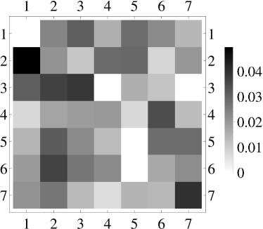
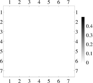
We do not include the effect of wetting via Van der Waal’s forces in the evolution equation. From hereon, we define rupture as that juncture in the computation when the effect of various non-linear terms in the evolution equation is to induce numerical stiffness at small film thicknesses. In our simulation cases, rupture occurs when the film thickness reaches about 3-4% of the initial film thickness. Physically, this rupture thickness translates to about for the dichloromethane film we simulate. From the discrete Fourier transform (DFT) plots (eg. figure 2), at rupture, the film profile shows the appearance of high frequency Fourier modes. The utility of the DFT plots is enabling the realization that as the film progresses toward rupture, higher frequencies appear. The fastest growing wavelength is the dominant mode. A cascade of higher frequencies is seen as gray spots. The DFT plots show all those frequencies that account for or more of the total energy at that stage in time.
4 Dichloromethane liquid film evaporating in zero gravity
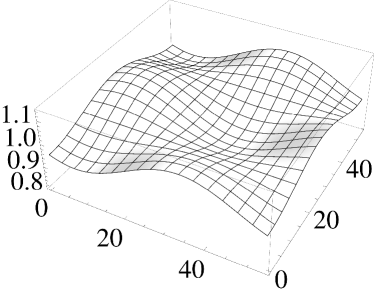
Two different initial conditions are used to perturb a DCM film evaporating in zero gravity. Figure 1 a smooth cosine initial condition and it’s discrete Fourier transform (DFT) frequency distribution is compared against a uniform random distribution. The smooth initial condition is generally used in literature.
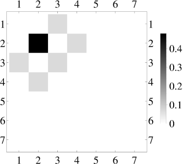
The evolution equation 2 is solved to simulate a 2.35mm thick Dichloromethane liquid film which is slowly evaporating. The non dimensional parameters for the Dichloromethane liquid film are compared with that of the mathematical fluid in table 3. The film is placed in a square domain whose side length is equal to about inches ( inches for a mm DCM film). When the film is perturbed by a smooth initial condition or a uniform random initial condition the film ruptures via long wave type/thermocapillary driven structures. The end result in figure 1 shows a cascade of Fourier modes in zero gravity. The dominant mode in the DFT plot is that which corresponds to the fastest growing wavelength, with the maximum growth rate.
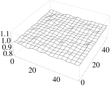
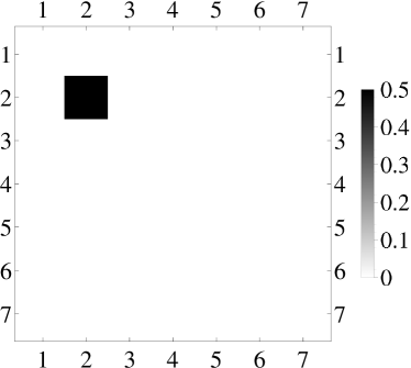
However, when the DCM evaporates in Earth’s gravity, the film is resistant to long wave type instabilities as seen by the blank DFT plot in figure 2 LABEL:sub@fig:2a. Hence a DCM film that is resistant to thermocapillary rupture in Earth’s gravitational field is destabilized in zero gravity and is driven to rupture. Another interesting observation is that in Earth’s gravity, the complete depletion of the liquid film takes place in about 1 minute. However, in a zero gravity environment, the film ruptures in around 4 seconds.
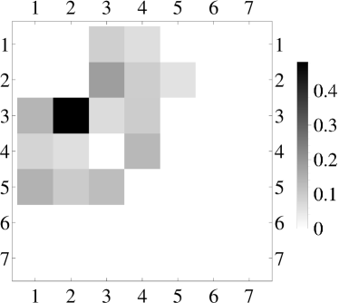
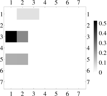
The domain size is now changed for this DCM film evaporating in zero gravity. We use a square domain with and a rectangular domain with . When the film is perturbed with a uniform random initial condition a cascade of frequencies with the fastest growing wavelength as the dominant mode emerges as seen in figure 3.
5 Criterion for film thickness for long wave destabilization
Based on gravity stabilization and thermocapillarity destabilization conditions, there exists a criterion for the growth of thermocapillarity driven long wave instabilities. For a certain balance between stabilizing (gravity, surface tension) and destabilizing (thermocapillarity, evaporative mass flux, vapor recoil) forces, the film thickness has an effect on whether or not long wave type instabilities manifest.
The growth rate of long wave instabilities can be used as a metric to define the film thickness criterion for long wave destabilization affecting evaporating liquid films in zero- and micro-gravity environment. The growth rate of long wave instabilities is given by the equation 3. This is derived from the method of linear stability applied to the evolution equation 2.
| (3) |
A positive growth rate () signifies a positive growth rate of long wave instabilities. Positive destabilizing growth rates occur in the case depicted in figure 2 LABEL:sub@fig:2a. A zero or negative growth rate signifies a damping of long wave instabilities. Negative, damping of instabilities occurs in figure 2 LABEL:sub@fig:2b.
The growth rate, , in equation 3 is function of film parameters , the excitation wavenumber, q and the mean film thickness . For a given excitation, q, given Bond number, and given strength of thermocapillarity, , the growth rate of long wave instabilities would depend on the mean film thickness, .
A plot depicting the trend of vs q for different film thicknesses is shown in figure 4 for zero gravity with , , and and in figure 5 for a marginally higher gravity with , , and .
The various curves in the vs q plots in figures 4 and 5 are for different film thicknesses (non-dimensional). A DCM film of thickness signifies a film thickness of mm. For a certain film thickness for an evaporating liquid film, the incidence of long wave instabilities decreases as the film thickness increases. In other words, thicker films are more resistant to long wave instabilities than thinner films for the corresponding liquid. As a film slowly evaporates, based on the gravity and thermocapillarity condition long wave instabilities may or may not manifest.
From this observation, it is possible to back-calculate a film thickness for zero gravity evaporation for which the film is resistant to long wave instabilities. In figure 6, DCM film thicknesses stable to long wave modes and those film thicknesses that represent zero growth rate are shown. Stabilization of long wave modes () occurs for thicker films. As the film grows thinner by evaporation, a stable DCM configuration can be rendered unstable and shows the existence of long wave modes leading to thermocapillary driven rupture.
6 Conclusions
The evolution equation describing long wavelength instabilities affecting thin evaporating liquid films is used to capture film dynamics of an evaporating dichloromethane liquid film in zero gravity and in Earth’s gravitational field. An expression for the fastest growing wavelength is derived. This expression allowed for zero gravity evaporation to be explored. The evolution equation and the expression for the fastest growing wavelength are validated against literature.
A mm thick dichloromethane liquid film evaporating in zero gravity shows interesting film dynamics when subject to a variety of initial condition and domain size combinations.
-
1.
A DCM film evaporating in Earth’s gravity is resistant to long wave type instabilities.
-
2.
An evaporating DCM film in zero gravity confined to a square domain when perturbed with a smooth initial condition or a uniform random perturbation shows the appearance of the fastest growing wavelength at rupture.
-
3.
When the domain shape is changed from a square to rectangle with length and width, the fastest growing wavelength appears as the dominant mode at rupture. A directional preference is seen in the DFT plots.
Zero gravity evaporation allows for evaporating DCM liquid films to be destabilized via long wave modes while a DCM film of the same thickness is robust and resilient to long wave type instabilities under the influence of Earth’s gravitational field.
The growth rate of long wave instabilities is derived from the linear stability analysis is used as a metric to calculate the film thickness which provides the DCM film resistance to long wave type instabilities. Various growth rate curves are calculated for different film thicknesses and it is observed that when a DCM film is evaporating in zero gravity, as the film thickness decreases, it is more easily affected by long wave type instabilities.
References
- Craster and Matar 2009 R. V. Craster and O. K. Matar. Dynamics and stability of thin liquid films. Reviews of Modern Physics, 81(3):1131–1198, August 2009.
- Pehlivan and Özdemir 2012 Hüseyin Pehlivan and Mustafa Özdemir. Experimental and theoretical investigations of falling film evaporation. Heat and Mass Transfer, pages 1–9, January 2012.
- Moresi 1988 M. Moresi. Apple juice concentration by reverse osmosis and falling film evaporation. Preconcentration and drying of food materials, pages 61–76, 1988.
- Agostini et al. 2007 Bruno Agostini, Matteo Fabbri, Jung E. Park, Leszek Wojtan, John R. Thome, and Bruno Michel. State of the art of high heat flux cooling technologies. Heat Transfer Engineering, 28(4):258–281, 2007.
- Darabi 2003 J. Darabi. Development of a chip-integrated micro cooling device. Microelectronics Journal, 34(11):1067–1074, November 2003.
- Marcinichen et al. 2010 Jackson B. Marcinichen, John R. Thome, and Bruno Michel. Cooling of microprocessors with micro-evaporation: A novel two-phase cooling cycle. International Journal of Refrigeration, 33(7):1264–1276, November 2010.
- Schramm and Novosad 1992 Laurier L. Schramm and Jerry J. Novosad. The destabilization of foams for improved oil recovery by crude oils: Effect of the nature of the oil. Journal of Petroleum Science and Engineering, 7(1-2):77–90, April 1992.
- Bergeron et al. 1993 V. Bergeron, M. E. Fagan, and C. J. Radke. Generalized entering coefficients: a criterion for foam stability against oil in porous media. Langmuir, 9(7):1704–1713, July 1993.
- Cheremisinoff 2003 Nicholas P. Cheremisinoff. Industrial Solvents Handbook. Marcel Decker, second edition, 2003.
- Rayleigh 1916 Rayleigh. On convective currents in a horizontal layer of fluid when the higher temperature is on the under side. Philo. Mag. Series, 32(6):529–546, 1916.
- Pearson 1958 J. R. A. Pearson. On convection cells induced by surface tension. Journal of Fluid Mechanics Digital Archive, 4(05):489–500, 1958.
- Benny 1966a D. J. Benny. Long waves on liquid films. Journal of Mathematics and Physics, 45(2):150–155, 1966a.
- Benny 1966b D. J. Benny. Long non-linear waves in fluid flows (long finite amplitude wave motions and interactions in inviscid fluid flows). Journal of Mathematics and Physics, 45:52–63, 1966b.
- Williams and Davis 1982 M. B. Williams and S. H. Davis. Nonlinear theory of film rupture. Journal of Colloid and Interface Science, 90(2):220–228, 1982.
- Burelbach et al. 1988 J. P. Burelbach, S. G. Bankoff, and S. H. Davis. Nonlinear stability of evaporating/condensing films. Journal of Fluid Mechanics, 195:463–494, 1988.
- Krishnamoorthy et al. 1995 S. Krishnamoorthy, B. Ramaswamy, and S. W. Joo. Spontaneous rupture of thin liquid films due to thermocapillarity: A full-scale direct numerical simulation. Physics of Fluids, 7(9):2291–2293, 1995.
- Vanhook et al. 1997 Stephen J. Vanhook, Michael F. Schatz, J. B. Swift, W. D. McCormick, and Harry L. Swinney. Long-wavelength surface-tension-driven benard convection: experiment and theory. Journal of Fluid Mechanics, 345(1):45–78, 1997.
- Oron et al. 1997 Alexander Oron, Stephen H. Davis, and S. George Bankoff. Long-scale evolution of thin liquid films. Rev. Mod. Phys., 69(3):931–980, Jul 1997.
- Oron 2000a Alexander Oron. Nonlinear dynamics of three-dimensional long-wave marangoni instability in thin liquid films. Physics of Fluids, 12(7):1633–1645, 2000a.
- Sultan et al. 2005 Eric Sultan, Areski Boudaoud, and Martine B. Amar. Evaporation of a thin film: diffusion of the vapour and marangoni instabilities. Journal of Fluid Mechanics, 543:183–202, 2005.
- Dietzel and Troian 2009 Mathias Dietzel and Sandra M. Troian. Formation of nanopillar arrays in ultrathin viscous films: The critical role of thermocapillary stresses. Physical Review Letters, 103(7):074501+, August 2009.
- Oron 2000b Alexander Oron. Three-dimensional nonlinear dynamics of thin liquid films. Phys. Rev. Lett., 85:2108–2111, Sep 2000b.
- Pradhan and Samal 1987 G. K. Pradhan and P. C. Samal. Thermal stability of a fluid layer under variable body forces. Journal of Mathematical Analysis and Applications, 122(2), 1987.
- Straughan 1989 Brian Straughan. Convection in a variable gravity field. Journal of Mathematical Analysis and Applications, 140(2), 1989.
- Ostrach 1982 I. Ostrach. Low gravity fluid flows. Annual Review of Fluid Mechanics, 14:313–345, January 1982.
- Hindmarsh 1987 A.C. Hindmarsh. Lsode: Livermore solver for ordinary differential equations. Technical report, Lawrence Livermore National Laboratory, March 1987.
- Struthers et al. 2010 A. Struthers, R.W. Kolkka, J.S. Allen, and A.D. Narendranath. Accurately resolving rupture in 4th order partial differential equations modeling thin films using ndsolve. Wolfram Technology Conference 2010, 2010.
- Oron and Bankoff 2001 Alexander Oron and S. George Bankoff. Dynamics of a condensing liquid film under conjoining/disjoining pressures. Physics of Fluids, 13(5):1107–1117, 2001.
7 Tables and Figures
| Parameter | Definition | Physics described |
|---|---|---|
| Surface tension | ||
| Gravity | ||
| Thermocapillarity | ||
| Pr | Momentum vs thermal diffusion | |
| Evaporation | ||
| Non equilibrium at interface | ||
| Buoyancy | ||
| Surface tension | ||
| Mean film thickness | ||
| Temperature | ||
| Mass density | ||
| Kinematic viscosity | ||
| Thermal diffusivity | ||
| Latent heat | ||
| Accommodation coefficient | ||
| Universal gas constant | ||
| Molecular weight |
| Case | Literature 19, 16 | MTU/UW |
|---|---|---|
| 93.78 | 93.78 (validation) | |
| – | 92.322 | |
| – | 79.1712 |
| DCM () | Math fluid (regular/zero g) | |
| Ga | / 0 | 0.333 / 0 |
| S | 100 | |
| M | 35.1 | |
| Pr | 7.02 | |
| 0 | ||
| 0 | ||
| m |