Theory of wetting-induced fluid entrainment by advancing contact lines on dry surfaces
Abstract
We report on the onset of fluid entrainment when a contact line is forced to advance over a dry solid of arbitrary wettability. We show that entrainment occurs at a critical advancing speed beyond which the balance between capillary, viscous and contact line forces sustaining the shape of the interface is no longer satisfied. Wetting couples to the hydrodynamics by setting both the morphology of the interface at small scales and the viscous friction of the front. We find that the critical deformation that the interface can sustain is controlled by the friction at the contact line and the viscosity contrast between the displacing and displaced fluids, leading to a rich variety of wetting-entrainment regimes. We discuss the potential use of our theory to measure contact-line forces using atomic force microscopy, and to study entrainment under microfluidic conditions exploiting colloid-polymer fluids of ultra-low surface tension.
Introduction.– The entrainment of a fluid by a solid raises fundamental questions on the hydrodynamics of moving contact lines Bonn et al. (2009), which are the intersection of fluid and solid boundaries, and is relevant to a wide variety of practical situations in materials science Stratford et al. (2005); Subramaniam et al. (2005) and microfluidics Utada et al. (2007); Leshansky et al. (2012). Fluid entrainment gives rise to rich phenomena such as bubble entrainment in solid plate immersion Blake and Ruschak (1979); Marchand et al. (2012), gas intrusion in coating Blake and de Coninck (2002); *BlakePatent and solid-liquid splashing Duez et al. (2007), drop emission from forced liquid microfilaments Ledesma-Aguilar et al. (2011), the ejection of drops and rivulets from forced running drops Podgorski et al. (2001); Peters et al. (2009) and the more familiar film deposition on withdrawn solid plates Maleki et al. (2007); Snoeijer et al. (2008).
Typically, entrainment has been studied when a liquid front is forced to retreat from a solid at constant driving speed, . Considerable theoretical progress has been made in understanding the stability of such receding configuration on hydrophilic substrates de Gennes (1986); Eggers (2004), where the static contact angle, or Young’s angle , is small. In this case, it is now well understood that the front can only dewet completely from the surface up to a maximum receding speed de Gennes (1986); Eggers (2004), where is the liquid/solid interfacial surface tension, is the liquid viscosity, and is a numerical prefactor specific to the system geometry. Above this threshold, the liquid is entrained by the solid and a thin film is left on the surface Snoeijer et al. (2008).
Despite being an archetype of forced liquid fronts, the advancing configuration, where a liquid moves over a solid surface displacing a gas, is understood to a much lower extent. For advancing contact lines, the front is also destabilized above a critical speed, . However, this can be significantly larger ( m s-1) than the receding speed () Peters et al. (2009). For a receding contact line the liquid dewets from the solid, while for an advancing contact line it is the gas. This asymmetry can be used to rationalize the gap in magnitudes between and ; upon retreating, the gas offers a smaller viscous friction than the liquid, and thus the destabilization threshold should be larger for the advancing configuration. Although a similar scaling, Duez et al. (2007), has been suggested for advancing contact lines on hydrophobic surfaces (where depends on the gas viscosity, ), this relation does not capture the experimentally reported dependence of on the wider range Blake and de Coninck (2002); Duez et al. (2007); Ledesma-Aguilar et al. (2011).
Increasing experimental evidence supports the important role of surface specificity on entrainment Blake and de Coninck (2002); Duez et al. (2007); Ledesma-Aguilar et al. (2011). A non-monotonic dependence of as is varied was observed when forcing water films on wafers covered with dry gelatin containing different surfactants Blake and de Coninck (2002). However, careful measurements displayed a dramatic saturation of on hydrophilic substrates made of glass, and a rapid decay with on hydrophobic solids (treated with silane chains) Duez et al. (2007). Similarly, can be controlled by wearing a superhydrophobic surface, suggesting that surface heterogeneity can lead to entrainment Ledesma-Aguilar et al. (2011). These examples illustrate the wide variety of situations where entrainment can arise, yet for which a general theoretical framework is lacking.
In this Letter we put forward a theoretical framework that combines the hydrodynamics of the advancing front with the dynamics of the contact line to predict the onset of fluid entrainment on surfaces of arbitrary wetting properties. Due to the strong sensitivity of the advancing front to the interfacial morphology, the maximum advancing speed of the front shows a rich behavior depending on the wetting properties of the solid and the viscosity contrast between the fluids. The coupling with the large-scale morphology of the front in our theoretical framework is generic; hence the reported results can be applied to a wide variety of fluid geometries.
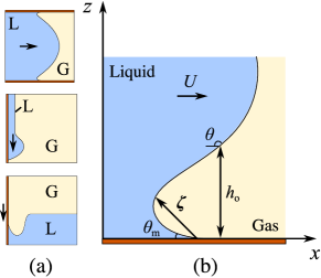
Theory.– Fig. 1(a) shows schematically typical liquid fronts advancing over dry substrates due to the action of different external forces, , e.g., a pressure gradient forcing a meniscus between parallel plates, gravity pushing a thin film down a vertical surface, or the drag caused by a solid plate that plunges into a liquid bath. At small scales the shape of the front is independent of geometry, and has the generic structure depicted in Fig. 1(b). Here we consider the motion of flat contact lines and focus on the variation of the front in the plane, with the solid surface located at . In steady state, the interface profile is described by the parametric curve which propagates at speed . The relevant condition for a steady interfacial state is that the total force per unit length of the contact line acting along the longitudinal coordinate, , vanishes,
| (1) |
where is the capillary force, and and are the viscous friction forces offered by the liquid and the gas. Since these forces depend on and , it is possible to recast Eq. (1) into a relationship between the interface shape and its velocity. Hence, the entrainment onset corresponds to the maximum speed for which the interface shape is consistent with the previous force balance.
Obtaining the maximum advancing speed, , is challenging because the interfacial shape follows from the solution of the non-linear free-boundary problem associated with the hydrodynamics of the liquid and gas phases, subject to boundary conditions at the solid surface. While numerically it is possible to solve the hydrodynamics for a specific geometry Marchand et al. (2012), this gives a less general understanding of the physics behind fluid entrainment. As an alternative, we will show that a good approximation of the curved interface profile captures the leading order behavior of the force balance.
The scale dependence of the competing terms in Eq. (1) gives rise to a natural division of the interface into two regions. At large scales, corresponding to an outer region, the interface shape is determined by the balance between the external forcing and capillarity (see Fig. 1(a)). This contrasts with a small-scale inner region, depicted in Fig. 1(b), where viscous stresses and capillarity are dominant. The cross-over between the outer and inner regions occurs at a thickness , comparable to the capillary length , where is the hydrostatic pressure gradient due to the external force. Since the front is driven externally, the stability of the interface is subject to the ability of the contact line to follow the leading front. Accordingly, we focus on the dynamics in the region close to the solid substrate. In the inner region the external force can be neglected while the capillary term corresponds to the dynamic Young’s force, , obtained integrating the gradient of the Laplace pressure, , for , where and are the the local curvature and inclination angle of the interface, is the molecular thickness, and is the microscopic contact angle with which the interface intersects the solid. The remaining terms in Eq. (1) are the friction forces, with , where refers to the area occupied by phase in the plane (Fig. 2(a)). The first term in accounts for the friction arising from the sliding motion of the fluid wedges meeting at the contact line, where the large-slope correction, , approaches unity for sharp wedges Snoeijer (2006), close to the entrainment threshold. The second term corresponds to viscous stresses arising far from the contact line and is characterized by order-unity numerical pre-factors, . Dividing through by , Eq. (1) reduces to
| (2) |
where is the capillary number and is the viscosity contrast between the fluids. This equation includes the effects of both moving phases, and can be used to describe advancing and receding fronts.
Previous results for receding contact lines correspond to the limit of small interface slopes Eggers (2004), and vanishing gas viscosity. This limit is recovered by setting and in Eq. (2), whereby one obtains . This expression is equivalent to the thin-film lubrication equation, as pointed out in Ref. Bonn et al. (2009), which can be used to obtain the well-known scaling for the maximum receding speed Eggers (2004).
The first challenge in using Eq. (2) is the divergence of viscous forces at the intersection between the fluid and solid boundaries Huh and Scriven (1971). To regularize this singularity we treat as a cut-off length scale. Hence, at the solid boundary the profile obeys
| (3) |
where determines the local structure of the interface at small scales. While for receding contact lines Cox (1986), for advancing fronts the interface slope can deviate from its static value for arbitrarily small distances from the solid surface due to the microscopic details of the contact line motion de Gennes (1986). We account for the detailed dynamics at the contact line assuming a local force balance, which to leading order in the front displacement can be expressed as Bonn et al. (2009)
| (4) |
where is a dimensionless friction coefficient that subsumes the specific microscopic details of the contact line motion Briant and Yeomans (2004); Qian et al. (2006). For advancing fronts the interface curvature changes sign at the cross-over thickness, , due to the external forcing, and its local slope is characterized by the dynamic angle, . The matching conditions of the inner region with the outer profile hence read
| (5) |
where is the local interfacial slope. Rather than using these conditions to relate the inner and outer profiles of a specific geometry, we consider a generic setting by treating as a given external interfacial deformation.
(a) (b)
To determine the interfacial profile, we use the local force-density balance , where the local capillary force, varying as , is balanced by the viscous force, scaling as . Since for advancing fronts the profile may develop overhangs, it is useful to invert the profile, , for small . Matching with the outer region through Eq. (5), we obtain both the interface profile
| (6) |
and 111See supplementary material for details. For small interfacial slopes 222This particular limit corresponds to the lubrication equation, which can be solved perturbatively in powers of .. Expanding in powers of , together with Eq. (3) to fix the profile at the contact line, one recovers the classic result where Cox (1986).
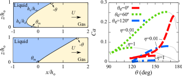
The wettability of the solid surface has a strong influence on the front morphology. To illustrate this we plot Eq. (6) in Fig. 2(a) for hydrophilic () and hydrophobic () surfaces for a fixed dynamic contact angle, . We fix the scale separation as for visualisation purposes, although such weak separation between microscopic and macroscopic lengthscales is realistic, e.g., for colloid-polymer demixed fluids Aarts et al. (2004). Due to the coupling to the solid at small scales, Eq. (3), the interface can bend forward to develop a foot on hydrophilic substrates (top panel). This structure appears whenever and extends from the molecular length, , to the turning point . The gas counterpart to the liquid foot is the wedge shown in Fig. 2(a), which can only form when . On hydrophilic substrates, when , the wedge is truncated and extends down to the thickness of the overhang at the contact line, (top panel), or down to the microscopic lengthscale for hydrophobic surfaces (bottom panel). Remarkably, Eq. (6) is a very good approximation to the interface profile even for large slopes, as shown by a direct comparison to lattice-Boltzmann simulations 333See supplement for details on the geometry of the interface (the size of the foot, and the depth of the gas wedge ), and details of the comparison to simulations.
With the shape of the interface, Eq. (6), we can now evaluate Eq. (2) to obtain
| (7) |
where . Note that, due to the definition of in Eq. (5), the curvature dependent term drops in Eq. (7).
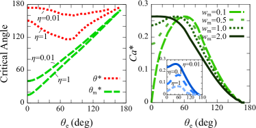
Discussion.– Eq. (7) determines the velocity of the liquid front as a function of the dynamic angle over the wide range imposed by the external forcing. As depicted in Fig. 2(b), increases from its equilibrium value with , indicating the morphological response of the interface to larger driving forces. Crucially, the capillary force in Eq. (7) can only sustain a maximum deformation, while the friction forces can grow indefinitely as . This implies that there is a maximum capillary number, , beyond which the force balance cannot be satisfied, leading to fluid entrainment. The set of maxima shown in Fig. 2(b) correspond to different critical interface deformations, and therefore depend on the small-scale coupling set by and on the viscous bending, controlled by . This is illustrated in Fig. 3(a), which shows that is reached at a critical dynamic angle, , weakly dependent on and is generally above for (representative of air-water systems). This changes for high , where a stronger viscous friction offered by the displaced phase leads to lower and . Similarly, the microscopic contact angle reaches a critical value, , at the onset of entrainment, which differs from the equilibrium angle by an amount set by the viscosity contrast.
(a) (b)
Remarkably, the maximum advancing speed, , depends on the static angle and on the contact line friction (Fig. 3(b)). On hydrophilic surfaces the friction due to the liquid foot controls . For small Eq. (4) yields , leading to a sharp foot that generates a larger amount of viscous friction. This increase in the viscous response becomes larger as , and therefore generates unstable fronts at smaller . The result is a non-monotonic dependence. For larger , the microscopic angle departs from , relaxing the friction offered by the foot. This effect eventually balances the capillary force, leading to a plateau-like behavior. Such remarkable surface specificity has been observed in experiments. In Ref. Blake and de Coninck (2002), water films were forced on surfactant-treated, dry aqueous gelatin surfaces, where was found to increase on hydrophilic surfaces to reach a maximum at . In Ref. Duez et al. (2007), a plateau for the splashing speed of glass beads treated with a hydrogen peroxide–sulphuric acid solution (hydrophilic beads) and a rapid decay for those grafted with silane chains (hydrophobic beads) was reported. Such a decay on hydrophobic surfaces is due to the absence of the liquid foot. Instead, the viscous friction is dominated by the gas wedge in front of the contact line, which becomes increasingly narrow as . In agreement with a previous analysis Duez et al. (2007), in the hydrophobic limit Eq. (7) reduces to
| (8) |
where is a numerical pre-factor that depends on the scale separation, . In this regime the critical advancing speed obeys , as indicated by the scaling of the capillary (l.h.s.) and friction (r.h.s.) terms in Eq. (8).
The viscosity contrast between the fluids also has a significant influence on fluid entrainment. Here we focus on the effect of the solid, which we illustrate in the inset of Fig. 3(b). While the critical point is shifted to a lower scale as is increased (reducing the gap between the advancing and receding critical velocities), the plateau-like behavior in hydrophilic substrates, due to the insensitivity of the advancing front to the foot shape at high , can persist to these variations. The critical dynamic angle, on the other hand, approaches 180∘ for decreasing viscosity of the displaced fluid, as has been shown numerically for plunging plate geometries Marchand et al. (2012). These results illustrate that the advancing configuration is distinct to the receding one due to the coupling between wetting, expressed in the shape of the profile, and the fluid viscosities.
Conclusions.– We have analyzed the impact of wetting on the onset of fluid entrainment on a forced advancing fluid front. We have put forward a general theoretical framework to identify the morphological origin of fluid entrainment and the asymmetric role played by the affinity of the solid substrate to the advancing front. Our theory highlights the relevance of the fluid foot that the forcing liquid develops when the front advances on hydrophilic surfaces. The change in structure of the fluid front close to the solid, and the relative viscosity between the moving fluids are then shown to be responsible for the asymmetry in the entrainment speed between advancing and receding configurations.
The rich variety of wetting-entrainment regimes found highlights the important role of surface properties, characterized by the contact line friction coefficient . Recent developments in atomic force microscopy (AFM) Xiong et al. (2009) can probe forces associated to contact line dynamics 444P. Tong, private communication, opening the possibility of quantifying the friction of the advancing contact line. The magnitude of the forces exerted on the probe support the feasibility of experiments that measure force profiles as a function of the immersion speed of a dipping probe. Neglecting buoyancy forces, the force exerted by the AFM probe of diameter is balanced by the vertical component of the interfacial tension , and by the viscous stress acting over the probe’s surface. For a m-wide probe Xiong et al. (2009), the order of magnitude of these forces (below the transition), is set by , and is of tens to hundreds of nano Newtons. A detailed observation of the entrainment in the microfluidic regime is also possible, by using laser scanning microscopy of microfluidic experiments of demixed colloid-polymer mixtures of ultra-low surface tension Aarts et al. (2004). Such experiments can be used to gain insight on the nature of the dynamic transition associated to entrainment and help in manufacturing substrates with well defined wetting properties to manipulate and better control the flow of liquid fronts at small scales.
We thank Dirk Aarts, Penger Tong and Luis Vázquez for enlightening discussions on the experimental applicability of our theory, and Andrew Clark and Chris Lenn for useful discussions. RLA acknowledges support from Marie Curie Actions (FP7-PEOPLE-IEF-2010 no. 273406). AHM acknowledges partial financial support from MICINN (Spain) under project FIS2009-192964- C05-02 and DURSI project SGR2009-00014. IP acknowledges financial support from MINECO (Spain) and DURSI under projects FIS2011- 22603 and 2009SGR-634, respectively.
References
- Bonn et al. (2009) D. Bonn, J. Eggers, J. Indekeu, J. Meunier, and E. Rolley, Rev. Mod. Phys. 81, 739 (2009).
- Stratford et al. (2005) K. Stratford, R. Adhikari, I. Pagonabarraga, J.-C. Desplat, and M. E. Cates, Science 309, 2198 (2005).
- Subramaniam et al. (2005) A. B. Subramaniam, M. Abkarian, and H. A. Stone, Nature Mater. 4, 553 (2005).
- Utada et al. (2007) A. S. Utada, A. Fernandez-Nieves, H. A. Stone, and D. A. Weitz, Phys. Rev. Lett. 99, 094502 (2007).
- Leshansky et al. (2012) A. M. Leshansky, S. Afkhami, M.-C. Jullien, and P. Tabeling, Phys. Rev. Lett. 108, 264502 (2012).
- Blake and Ruschak (1979) T. D. Blake and K. J. Ruschak, Nature 282, 489 (1979).
- Marchand et al. (2012) A. Marchand, T. S. Chan, J. H. Snoeijer, and B. Andreotti, Phys. Rev. Lett. 108, 204501 (2012).
- Blake and de Coninck (2002) T. D. Blake and J. de Coninck, Adv. Coll. Int. Sci. 96, 21 (2002).
- Blake and Morley (1998) T. D. Blake and S. D. Morley, US Patent 5,792,5155 , (1998).
- Duez et al. (2007) C. Duez, C. Ybert, C. Clanet, and L. Bocquet, Nat. Phys. 3, 180 (2007).
- Ledesma-Aguilar et al. (2011) R. Ledesma-Aguilar, R. Nistal, A. Hernández-Machado, and I. Pagonabarraga, Nature Mater. 10, 367 (2011).
- Podgorski et al. (2001) T. Podgorski, J. M. Flesselles, and L. Limat, Phys. Rev. Lett. 87, 036102 (2001).
- Peters et al. (2009) I. Peters, J. H. Snoeijer, A. Daerr, and L. Limat, Phys. Rev. Lett. 103, 114501 (2009).
- Maleki et al. (2007) M. Maleki, E. Reyssat, D. Quéré, and R. Golestanian, Langmuir 23, 10116 (2007).
- Snoeijer et al. (2008) J. H. Snoeijer, J. Ziegler, B. Andreotti, M. Fermigier, and J. Eggers, Phys. Rev. Lett. 100, 244502 (2008).
- de Gennes (1986) P. G. de Gennes, Colloid Polymer Sci. 264, 463 (1986).
- Eggers (2004) J. Eggers, Phys. Rev. Lett. 93, 094502 (2004).
- Snoeijer (2006) J. H. Snoeijer, Phys. Fluids 18, 021701 (2006).
- Huh and Scriven (1971) C. Huh and L. Scriven, J. Colloid Interface Sci. 35, 85 (1971).
- Cox (1986) R. G. Cox, J. Fluid Mech. 168, 169 (1986).
- Briant and Yeomans (2004) A. J. Briant and J. M. Yeomans, Phys. Rev. E 69, 031603 (2004).
- Qian et al. (2006) T. Qian, X.-P. Wang, and P. Sheng, J. Fluid Mech. 564, 333 (2006).
- Note (1) This particular limit corresponds to the lubrication equation, which can be solved perturbatively in powers of .
- Note (2) See supplementary material for details.
- Aarts et al. (2004) D. G. A. L. Aarts, M. Schmidt, and H. N. W. Lekkerkerker, Science 304, 847 (2004).
- Note (3) See supplement for details on the geometry of the interface (the size of the foot, and the depth of the gas wedge ), and details of the comparison to simulations.
- Xiong et al. (2009) X. Xiong, S. Guo, Z. Xu, P. Sheng, and P. Tong, Phys. Rev. E 80, 061604 (2009).
- Note (4) P. Tong, private communication.