Two-colour generation in a chirped seeded Free-Electron Laser
Abstract
We present the experimental demonstration of a method for generating two spectrally and temporally separated pulses by an externally seeded, single-pass free-electron laser operating in the extreme-ultraviolet spectral range. Our results, collected on the FERMI@Elettra facility and confirmed by numerical simulations, demonstrate the possibility of controlling both the spectral and temporal features of the generated pulses. A free-electron laser operated in this mode becomes a suitable light source for jitter-free, two-colour pump-probe experiments.
Introduction
Chirped pulse modulation is a widely used technique, with relevant applications in several fields of research, ranging from digital communication [1] to radar detection [2], and from optics [3] to laser physics. In a broadband laser, frequency chirping is employed to stretch a short pulse prior to amplification. This stretching and the associated lower intensity mitigates the problem of phase distortion in the amplification medium. After pulse amplification, the pulse is recompressed to recover a short duration and, hence, high power [4]. A similar method has been proposed [5, 6, 7] to enhance the power generated by a single-pass seeded free-electron laser (FEL) working in the so-called coherent harmonic generation (CHG) regime [8]. After amplification and removal of the chirp, one in principle can obtain a high power, nearly Fourier-transform-limited pulse.
In this paper, we characterize the performance of a seeded FEL where frequency chirping on the seed laser is instead exploited to generate two independent pulses spectrally and temporally separated in an externally controllable fashion. As previously shown in [9], this opens the possibility of using a chirped-seeded FEL as a self-standing source for pump-probe experiments in the vacuum ultraviolet and X-ray spectral domain.
The paper is divided into the following parts: in Section 1 we introduce the principle upon which a CHG FEL is based, with specific reference to the case of the FERMI@Elettra FEL [13]. We then qualitatively describe the formation of the double spectral peak, when the seed laser carries a linear frequency chirp. In Section 2, we give a description of the effects due to both a laser frequency chirp and an electron beam energy chirp. Then in Section 3, we present the results obtained on the FERMI@Elettra FEL and, in Section 4, compare them to numerical simulations. Finally, we summarize our conclusions and provide some perspectives for future experimental studies.
1 Formation of the spectral double peak
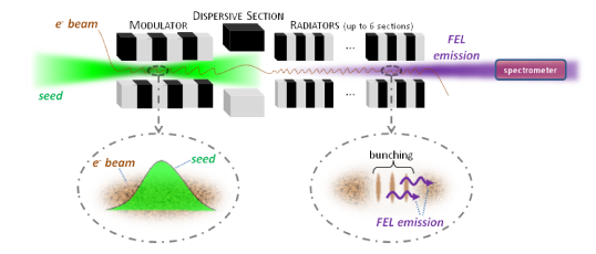
A CHG FEL such as FERMI@Elettra typically employs a layout similar to that shown in Fig. 1. A relativistic electron beam first propagates through the periodic field generated by an undulator, called the modulator, simultaneously interacting with a powerful coherent light source (e.g., a low-order harmonic of a Ti:Sapphire laser). This interaction coherently modulates the electron energy which then leads to a longitudinally-regular charge distribution after the electrons pass through a chromatically-dispersive magnet. Such a spatial modulation, called bunching, has nonzero spectral components at both the seed wavelength and at its higher harmonics. After the dispersive section, electron beam enters one or more additional undulators (called the radiators), whose normalized magnetic deflection parameters are tuned for fundamental FEL resonance to occur at an integral harmonic of the seed wavelength:
| (1) |
Here is the undulator period, the harmonic order and is the relativistic Lorentz factor characterizing the mean energy of the electron beam.
The resultant FEL radiation, which is highly temporally coherent due to the periodic bunching, can undergo quadratic (low-gain regime) or exponential (high-gain regime) amplification. For a sufficiently long radiator, the FEL process will reach saturation. The main parameters of the FERMI@Elettra configuration relevant for our experimental studies are listed in Table 1 and its caption. One should note that on FERMI@Elettra the seed pulses are much shorter than the electron beam. This is a critical point both for the spectral quality of the FEL emission and the spectro-temporal pulse-splitting phenomenon.
| Electron beam | Mean energy | GeV |
| Peak current | A | |
| Duration (FWHM) | ps | |
| Seed | Central wavelength | nm |
| Temporal profile | Gaussian | |
| Duration (FWHM) | fs | |
| Energy | J | |
| Transverse size (RMS) | m | |
| Modulator | Period | mm |
| Number of periods | ||
| Dispersive section | m | |
| Radiators | Number | 2 |
| Harmonic order | 6 | |
| Period | mm | |
| Number of periods |
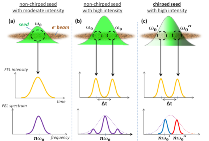
As shown in Fig. 2a, under conditions of moderate seed power and a temporally flat (i.e, both in energy and current) electron beam, the spectro-temporal properties of CHG mimic those of the seed [12, 13]: starting with a Gaussian seed pulse with a given duration and wavelength , one ends up with an output Gaussian CHG pulse at wavelength with slightly shorter duration[14] . However, this statement (which, in the temporal domain, is mainly a prediction of numerical simulations, due to the lack of temporal diagnostics in the vacuum-ultraviolet spectral range), is true only under certain limits and depends on the regime of operation of the FEL. Indeed, when increasing the seed power, the temporal edges of the seed pulse are also able to produce strong bunching at entrance to the radiator so that a larger part of the electron beam emits intense FEL radiation, giving a longer FEL pulse. For very high seed powers, the electron-beam energy modulation at the peak of the seed (i.e., the central position for a Gaussian) becomes too strong for the particular value characterizing the strength of the dispersive section. Then there is an overbunching effect and the resultant bunching in the radiator is strongly depressed. Thus, the FEL emission from this central position falls. On the other hand, there are two temporal positions with lower seed power, symmetric with respect to the peak of the seed, that match the optimum bunching condition for a given . Accordingly, the FEL signal grows and reaches the maximum intensity in these regions. This scenario is represented in Fig. 2b. For a sufficiently strong seed intensity, the FEL power at the central position almost vanishes and two successive pulses appear, as previously described in [15]. This phenomenon becomes particularly interesting if the seed is chirped i.e., if its frequency depends on the longitudinal position. As shown in Fig. 2c, in this situation the split temporal pulses have also different frequencies. In other words, two independent pulses with two different frequencies are created [9].
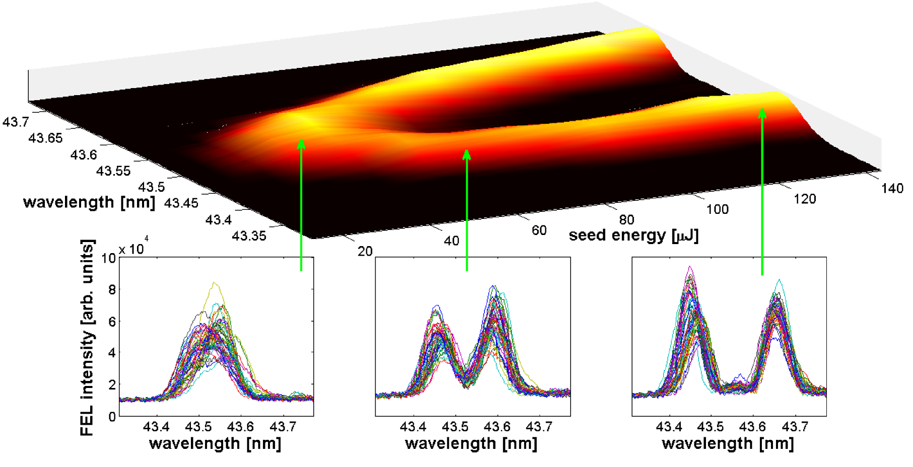
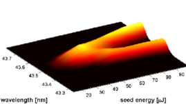
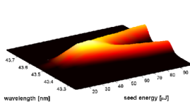
Two-colour pulse generation by a seeded FEL was observed for the first time [16] early in 2011 during the commissioning of FERMI@Elettra. A typical measurement of the FEL spectrum as a function of the seed power is shown in Fig. 3. By increasing the seed energy, the portion of electrons getting over-bunched increases, leading to a larger separation of the spectral peaks. As shown in the figure insets, the two-colour spectra are very stable on a shot-to-shot basis with very good repeatability. We obtained very similar pulse-splitting results by increasing the strength of the dispersive section while keeping the seed power constant (this is illustrated later in Fig. 7).
The spectro-temporal properties of the FEL emission are also affected by the quality of the electron beam. In particular, effects due to an energy chirp (i.e., the mean electron energy varies with longitudinal position) can couple with those from the frequency chirp carried by the seed laser. This interplay may have an impact on the process of formation of the two peaks, as well as on their spectral and temporal separations. In order to better explain the process of production of the double peak, we will now provide a description of the seed laser and electron beam chirps, with particular reference to the case of FERMI@Elettra.
2 Description of seed and electron beam chirps
Seed pulse: frequency chirp
The seed pulse used at FERMI@Elettra is the third harmonic of a Ti:Sapphire laser; both the temporal and spectral profiles are well fit by a Gaussian dependence [17]. The presence of a linear frequency chirp can be modelled by a quadratic term in the phase of the laser electric field:
| (2) |
Here A(t) stands for the temporal envelope while the exponential term carries the phase of the oscillations, including the rapidly-oscillating term at the central angular frequency and the quadratic term . The parameter is given by:
| (3) |
and being the standard deviations of the temporal intensity profile and the spectrum, respectively. The sign of corresponds to the sign of the induced frequency dispersion. In the setup adopted at FERMI@Elettra, the frequency dispersion of the seed pulse may be controlled in three different (but eventually combined) ways: (1) by propagation of the seed through different materials; (2) by passage through a dedicated set of gratings; and (3) by increasing the seed intensity, which causes self-phase modulation [18]. It is worth noting that in the presence of self-phase modulation, the chirp cannot be considered as being linear at or near the edges of the pulse. Moreover, the self-modulation process is associated with a spectral broadening. This broadening has been measured and taken into account in the present study. We also note that, for the experiments reported in this paper, the Gaussian shape of the pulse is preserved over the full range of seed energies.
The instantaneous frequency of the pulse is the derivative of the temporal phase (see Eq. 2):
| (4) |
Positive ’s define a positive linear chirp; i.e., smaller frequencies (longer wavelengths) arrive first. On the contrary, negative chirps arise for negative values. In both cases, two parts of the pulse separated by a duration have different frequencies, whose separation is, according to Eq. 4:
| (5) |
For a CHG FEL that operates in the pulse splitting regime, with the radiators tuned at the harmonic and the two sub-pulses separated by , we thus expect the frequency separation between the two spectral peaks to be:
| (6) |
For the sake of convenience, in the reminder of this paper, we will speak in terms of wavelength , instead of angular frequency and will therefore consider as the spectral separation of the two peaks of the FEL emission.
For a given spectral bandwidth, the presence of chirp in the seed pulse will increase its temporal duration.
At two positions separated by and symmetric with respect to the center of the pulse, the electron bunch experiences of the maximum intensity of a Gaussian profile seed. For our seed laser parameters, efficient seeding seems difficult below of the peak intensity, i.e., on the very far edges of the seed pulse.
Therefore, we may consider as the maximum practically achievable for a given chirp.
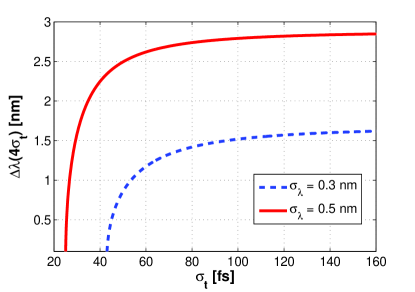
Figure 4 displays the evolution of the spectral separation between parts of the seed located at a distance , as a function of . Two different values of the bandwidth have been considered, corresponding to the two limiting cases at FERMI@Elettra: for a seed energy per pulse below J, the spectral bandwidth is close to nm whereas, for higher energies and thus intensities, nonlinear effects can broaden the spectrum up to nm. For increasing values of (i.e., for an increasing amount of chirp), reaches an asymptotic value.
Examining Fig. 4, one therefore sees for the case of FERMI@Elettra is limited to about nm. This information is important because it sets an effective limit to the spectral separation of the two pulses generated by the FEL.
Electron beam: energy chirp
As is now well known for CHG FEL’s in which the electron beam acts as an intermediary in carrying the coherent seed signal, temporal variations such as chirps in the energy profile may seriously impact the FEL output emission (see, e.g., [19, 20, 21, 22, 23]). A linear electron beam energy chirp, whose slope will be noted , couples to the total chromatic dispersion of the dispersive section and downstream undulators resulting in a simple shift of the central wavelength of FEL emission [20]. In principle, any corresponding gain reduction due to this shift can be compensated by either retuning the resonant wavelength of the undulators (see Eq. 1) or by slightly adjusting the seed wavelength. However, a quadratic chirp component will result in spectral broadening of output emission [21, 23] and, for sufficiently large magnitudes, can also reduce the FEL gain if the broadening becomes a significant fraction of the FEL’s gain bandwidth. In principle, here too the effect can be compensated by placing an equal magnitude but negative chirp on the seed pulse [24]. In the context of the subject matter of this paper, namely the formation and control of a double spectro-temporal peak, a quadratic electron beam energy chirp can either enhance or reduce the spectral offset between the two peaks and thus must be carefully taken into account.
A simple linear and quadratic energy chirp can be modelled as:
| (7) |
The exact amplitudes of the and coefficients at entrance to the FEL depend upon various propagation effects as the electron beam is transported through the linear accelerator (linac). First of all, the radio-frequency (RF) accelerating fields [25] of the successive linac sections (generally phased at or very close to crest) induce a negative quadratic chirp. Second, in order to increase the electron beam current (and thus enhance the FEL emission), the electron bunch is time-compressed. On FERMI@Elettra, this is done by first imposing a positive linear chirp component via phasing of two upstream linac sections off crest, and then by sending the electron beam through a magnetic chicane that converts the linear energy chirp into longitudinal compression. However, this procedure generates an additional negative curvature of the temporal energy profile. In order to linearize the longitudinal electron-beam phase space during the compression (generally necessary to have a relative constant current profile), an X-band, 4th high-harmonic RF cavity [26] positioned just upstream of the chicane is run close to negative crest to provide a positive contribution to the coefficient and compensate the aforementioned negative curvature. Following compression, strong longitudinal wakefields [27] in the downstream linac act upon the much higher current electron beam bunch: they induce a chirp that contains both a linear, negative term and a positive curvature component. While the linear coefficient can be eliminated by slightly dephasing off crest the last couple RF linac sections (at a price of a small reduction in final beam energy), there is no simple way to reduce the quadratic coefficient and therefore in general the electron beam enters the FEL with a quadratic energy chirp.
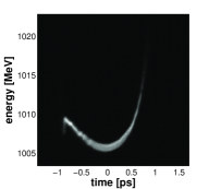
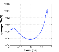
At FERMI@Elettra, we characterize the electron beam longitudinal phase space at the end of the linac via a diagnostic section composed of an RF deflecting cavity [28] followed by an energy spectrometer. The cavity stretches the beam in the vertical direction, inducing a correlation between the temporal distribution and the vertical displacement. The bending magnet chromatically disperses the electrons in the horizontal plane, making the information about the beam energy profile available along that direction. The beam longitudinal phase space can then be visualized on a fluorescent YAG crystal + CCD camera system placed downstream, as shown in Fig. 5. This particular distribution corresponds to the configuration in which most of the results presented in this paper have been obtained. The energy profile is very close to a parabola with a quite small linear component (i.e., Mev/ps) and a much more significant quadratic component with Mev/ps2. In Section 4 we consider the impact of this quadratic component upon double peak formation.
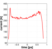
As shown in the right panel of Fig. 5, the current profile is almost flat in the middle of the bunch, even if a slow ramp towards the tail can be noticed. Experimentally, there is a typical shot-to-shot jitter of fs of the relative electron beam-seed timing. This jitter in conjunction with current inhomogeneities results in a fluctuation of the FEL power, as the seed “explores” different temporal portions of the beam. This effect may be relevant for user applications but does not affect the formation of the spectro-temporal double peak.
We now give a quantitative description of the two-colour emission results at FERMI@Elettra.
3 Experimental results
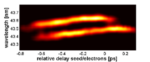
Figure 6 shows the behaviour of the FEL spectrum at the harmonic of the seed (43.5 nm) as one sweeps the relative time delay between the seed and the electron beam. To the best of our knowledge, this picture provides the first direct experimental evidence of the temporal pulse splitting in an FEL due to local overbunching induced by an intense seed. At a delay ps, the seed is superimposed on the electron beam tail, so that the first peak (at larger wavelength, since the frequency chirp is positive) appears. Then, at a delay ps, the whole seed pulse lies on top of sufficiently high current portions of the electron beam and the second peak (at shorter wavelength) also appears.
As we remarked in the previous section, a linear energy chirp of the electron energy induces a spectral shift of the FEL emission. Hence, when they appear near the tail portion of the electron beam, both peaks are detuned towards shorter wavelengths because of the strong local negative slope of the electron beam chirp (see Fig. 5). For smaller relative timing delays (i.e., moving the seed from overlapping the tail toward the head of the bunch), the central wavelengths of the two peaks drift redward due to the increase of the value of the local linear chirp of the electron energy distribution. However, the separation between the two spectral peaks (nm), their relative heights and their respective widths remain practically constant. The wavelength drift flattens out about fs before the first spectral peak disappears; this behaviour is mirrored fs later in the second peak. This early disappearance might be caused by the small current ramp from the center of the bunch to its tail (see Fig. 5) and/or by degraded transverse properties in this region.
In this experiment, the external seed chirp was created both during the propagation through different optical components such as lenses and windows, and by self-phase modulation due to high intensity. We typically measured a seed bandwidth nm and a duration fs (determined by cross-correlating the seed pulse with an infrared pulse, extracted from the oscillator of the Ti:Sapphire laser chain, whose FWHM duration fs). This gives fs-2, leading to the retrieval of the theoretical separation between the two sub-pulses, defined in Section 2. From Eqs. 5 and 6, we obtain:
| (8) |
where is the speed of light. For an harmonic order , fs (equal to ). The accuracy of this result will in principle be affected by the intrinsic chirp induced in the radiation during the FEL process [29] and by any quadratic energy chirp on the electron bunch. However, the size of the former is usually quite small relative to other chirps and the contribution of the latter is minor for our conditions, as will be confirmed in Section 4.
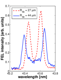
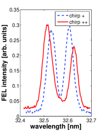
Up to now, we mainly focused on the effect of the seed power upon double spectro-temporal pulse formation. However, other parameters can influence the production and separation of the peaks. One is the strength of the dispersive section, as already discussed in [9] and experimentally demonstrated here in Fig. 7. Indeed, the dispersive section has an effect very similar to that of the seed power: the higher its strength, the lower the required seed power to produce a double pulse. Some small differences in the trend may be observed essentially because changing the seed intensity may affect the non-linear optical material dispersion and thus the chirp, while this does not happen when the is varied. Similarly, when employing a strong dispersive section, a moderate seed power can be sufficient to increase the peaks separation. Fig. 7 shows a different way to modify the spectral separation of the two pulses, i.e., by changing the seed chirp. However, increasing the seed chirp above a given limit does not produce any significant change in the FEL spectrum. This can be expected from the limitation of shown in Fig. 4.
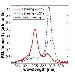
Also the relative heights of the peaks can be easily controlled, favouring the growth of one over the other, by tuning the wavelength corresponding to FEL resonance of the undulators. The spectrum represented by the dotted line in Fig. 8 corresponds to a central tuning of the undulators. The data represented by the solid line were taken at slightly negative detuning; while both peaks can be seen, the one at shorter wavelength is significantly stronger. The dashed curve shows a situation where the detuning is positive, for which the peak of the gain curve has moved to longer wavelengths. Here the shorter wavelength pulse has been almost completely suppressed.
4 Simulations
The formation of the double peak is well reproduced by simulations [9] carried out using both 3D [30] and 1D numerical codes [31]. Figure 9 shows a comparison of the spectral pulse splitting between the experimental data and 1D Perseo code simulations. As it can be seen, the agreement is very satisfactory. Note that in the simulations, the relative power before splitting is slightly higher than the one measured experimentally.
Let us now focus on one single measurement. Figure 10 shows the predicted spectrum and temporal profiles, obtained for simulation parameters that allow a good reproduction of the dashed-line spectrum reported in Fig. 7. The simulations have been carried out both for an ideal (i.e., flat in current and in energy) electron beam (dashed line), and the “real” electron-beam energy distribution shown in Fig. 5 (solid line). As shown in the left panel of Fig. 10, the positions of the spectral peaks are similar for the two cases: a slight reduction of the pulse separation on the order of nm can be observed in the “real” case. Such a small contribution may be neglected in our conditions and, in any case, the double peak formation is not affected. Moreover, if we calculate using Eq. 8 the theoretical separation between the two sub-pulses in the spectrum represented in Fig. 7, we find fs. This is close to the value found in the simulation (right panel of Fig. 10), that is fs. Therefore, we claim that the agreement between theoretical, experimental and numerical studies can be considered as very satisfactory.
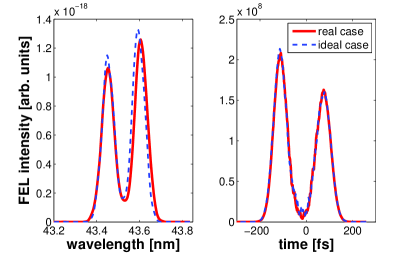
For this set of data, the spectral peaks have similar bandwidths , and the temporal pulses have similar durations, i.e., . According to these numbers, the duration of each sub-pulse is times greater than the Fourier-transform limit for a Gaussian spectrum. The distance from the Fourier-transform limit can be further reduced, e.g. by tuning the chirp of the seed laser. Since the seed and thus the FEL pulses are chirped, one could have expected a significant negative impact on the time-bandwidth product of each sub-pulse. However, this is not the case since each peak is quite narrow, and therefore barely sees the phase curvature of the seed electric field. Moreover, this also indicates that the phase of FEL pulses does not present high-order distortions.
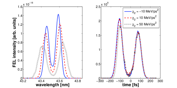
Before concluding, let us consider a situation where the quadratic chirp of the electron beam is no longer negligible. We carried out simulations with same parameters as before for several values of quadratic chirp, but without any linear component (i.e., MeV/ps2). In Fig. 11, we see that the value of has almost no effect on the temporal shape of the FEL emission but that, as already stated in Section 2, the individual bandwidths and separation of the two spectral peaks are directly affected. Consequently, a quadratic energy chirp of the electron beam acts on the spectrum in a very similar way as does a linear chirp of the seed laser, and thus both may be used individually or in conjunction to modulate the spectral shape of the FEL emission.
Conclusion
We studied the mechanism leading to the generation of two spectrally- and temporally-separated radiation pulses for a seeded, harmonic upshift free-electron laser operating in the extreme ultra-violet spectral region. This mechanism, discovered and studied in detail at the FERMI@Elettra FEL facility, relies on the use of a high-power chirped seed pulse to produce strong, coherent overbunching in an electron beam; the presence of the chirp is the key element to producing a spectral splitting between the two temporal pulses. By changing either the seed laser power or the strength of the dispersive section, we demonstrated excellent control of both the temporal distance and the spectral separation between the generated pulses. We also found that for our particular operation regime, the onset of the pulse splitting and the control of the pulses properties are only slightly affected by temporal variations in electron beam properties such as the current. Quadratic energy chirps do affect the spectral bandwidths and separation between the two pulses, but have negligible effect on their temporal separations. In the limit that radiation/electron beam slippage effects are small, the temporal separation between pulses can be directly retrieved from the measurement of the FEL spectrum and from the knowledge of the seed chirp properties. Such information can be extremely important when exploiting this two-pulse configuration to carry out jitter-free, pump-probe user experiments.
Acknowledgements
We gratefully acknowledge the valuable contribution of the FERMI@Elettra commissioning and operations team. We also profited from insightful discussions with F. Bencivenga, C. Callegari, F. Capotondi and M. Labat. This work was funded by the FERMI@Elettra project of Elettra-Sincrotrone Trieste, partially supported by the Ministry of University and Research under grant numbers FIRB-RBAP045JF2 and FIRB-RBAP06AWK3. The work of B. Mahieu, G. De Ninno and D. Gauthier has been partially supported by the CITIUS project, funded by the Program for cross-border cooperation Italy-Slovenia 2007-2013.
References
- [1] A. Berni and W. Gregg, “On the utility of chirp modulation for digital signaling,” IEEE Transactions on Communications 21, 748–751 (1973).
- [2] D. Mihovilovic and R. N. Bracewell, “Adaptive chirplet representation of signals in the time–frequency plane,” Electronics Letters 27, 1159–1161 (1991).
- [3] R. Szipöcs, K. Ferencz, C. Spielmann and F. Krausz, “Chirped multilayer coatings for broad-band dispersion control in femtosecond lasers,” Opt. Lett. 19, 201–203 (1994).
- [4] D. Strickland and G. Mourou, “Compression of amplified chirped optical pulses,” Opt. Commun. 55, 447–449 (1985).
- [5] L. H. Yu, E. Johnson, D. Li and D. Umstadter, “Femtosecond free-electron laser by chirped pulse amplification,” Phys. Rev. E 49, 4480 (1994).
- [6] F. Frassetto, L. Giannessi and L. Poletto, “Compression of XUV FEL pulses in the few-femtosecond regime,” Nucl. Instr. and Meth. A 593, 14–16 (2008).
- [7] C. Feng, L. Shen, M. Zhang, D. Wang, D. Zhao and D. Xiang, “Chirped-pulse amplification in a seeded free-electron laser for generating high-power ultra-short radiation,” Nucl. Instr. and Meth. A (2013).
- [8] L. H. Yu, “Generation of intense uv radiation by subharmonically seeded single-pass free-electron lasers,” Phys. Rev. A 44, 5178 (1991).
- [9] G. De Ninno, B. Mahieu, E. Allaria, L. Giannessi and S. Spampinati, “Chirped Seeded Free-Electron Lasers: Self Standing Light Sources for Two-colour Pump-Probe Experiments,” Phys. Rev. Lett. 110, 064801 (2013).
- [10] C. Svetina, A. Abrami, I. Cudin, C. Fava, S. Gerusina, R. Gobessi, L. Rumiz, G. Sostero, M. Zangrando and D. Cocco, “Characterization of the FERMI@Elettra’s on-line photon energy spectrometer,” Proc. SPIE 8139, 81390J (2011).
- [11] M. Zangrando, A. Abrami, D. Cocco, C. Fava, S. Gerusina, R. Gobessi, N. Mahne, E. Mazzucco, L. Raimondi, L. Rumiz, C. Svetina and F. Parmigiani, “The photon beam transport and diagnostics system at FERMI@Elettra, the Italian seeded FEL source: commissioning experience and most recent results,” Proc. SPIE 8504, 850404 (2012).
- [12] G. De Ninno, E. Allaria, M. Coreno, F. Curbis, M. B. Danailov, E. Karantzoulis, A. Locatelli, T. O. Menteş, M. A. Nino, C. Spezzani, and M. Trovò, “Generation of Ultrashort Coherent Vacuum-Ultraviolet Pulses Using Electron Storage Rings: A New Bright Light Source for Experiments,” Phys. Rev. Lett. 101, 053902 (2008).
- [13] E. Allaria, R. Appio, L. Badano, W.A. Barletta, S. Bassanese, S.G. Biedron, A. Borga, E. Busetto, D. Castronovo, P. Cinquegrana, S. Cleva, D. Cocco, M. Cornacchia, P. Craievich, I. Cudin, G. D’Auria, M. Dal Forno, M.B. Danailov, R. De Monte, G. De Ninno, P. Delgiusto, A. Demidovich, S. Di Mitri, B. Diviacco, A. Fabris, R. Fabris, W. Fawley, M. Ferianis, E. Ferrari, S. Ferry, L. Froehlich, P. Furlan, G. Gaio, F. Gelmetti, L. Giannessi, M. Giannini, R. Gobessi, R. Ivanov, E. Karantzoulis, M. Lonza, A. Lutman, B. Mahieu, M. Milloch, S.V. Milton, M. Musardo, I. Nikolov, S. Noe, F. Parmigiani, G. Penco, M. Petronio, L. Pivetta, M. Predonzani, F. Rossi, L. Rumiz, A. Salom, C. Scafuri, C. Serpico, P. Sigalotti, S. Spampinati, C. Spezzani, M. Svandrlik, C. Svetina, S. Tazzari, M. Trovo, R. Umer, A. Vascotto, M. Veronese, R. Visintini, M. Zaccaria, D. Zangrando and M. Zangrando, “Highly coherent and stable pulses from the FERMI seeded free-electron laser in the extreme ultraviolet”, Nat. Photonics 6, 699–704 (2012).
- [14] G. Stupakov, “Effect of finite pulse length and laser frequency chirp on HGHG and EEHG seeding,” SLAC Report No. SLAC-PUB-14639 (2011).
- [15] M. Labat, N. Joly, S. Bielawski, C. Szwaj, C. Bruni, and M. E. Couprie, “Pulse Splitting in Short Wavelength Seeded Free Electron Lasers,” Phys. Rev. Lett. 103, 264801 (2009).
- [16] E. Allaria, “FEL commissioning at FERMI@Elettra,” talk at Free-Electron Laser Conference 2011, WEOBI1.
- [17] M. B. Danailov, A. Demidovich, R. Ivanov, I. Nikolov, P. Sigalotti, P. Cinquegrana, “Desing and first experience with the FERMI seed laser,” in Proceedings of the Free-Electron Laser Conference 2011, TUOC4.
- [18] J. C. Diels and W. Rudolph, “Ultrashort laser pulse phenomena,” Academic Press (2006).
- [19] S.G. Biedron, S.V. Milton, H.P. Freund, ”Modular approach to achieving the next-generation X-ray light source,” Nucl. Instr. and Meth. A, 475, 401 (2001).
- [20] T. Shaftan and L. H. Yu, “High-gain harmonic generation free-electron laser with variable wavelength,” Phys. Rev. E 71, 046501 (2005).
- [21] W. Fawley and G. Penn, ”Thoughts on Spectral Broadening Effects in FERMI and other FELs Based upon Seeded Harmonic Generation,” FERMI Tech. Note ST/F-TN-06/07 (2006).
- [22] A. A. Lutman, G. Penco, P. Craievich and J. Wu, “Impact of an initial energy chirp and an initial energy curvature on a seeded free electron laser: the Green’s function,” J. Phys. A: Math. Theor. 42, 045202 (2009).
- [23] A. A. Lutman, G. Penco, P. Craievich and J. Wu, “Impact of an initial energy chirp and an initial energy curvature on a seeded free electron laser: free electron laser properties,” J. Phys. A: Math. Theor. 42, 085405 (2009).
- [24] W. Graves, private communication.
- [25] T. P. Wangler, “RF linear accelerators,” Wiley-VCH (2008).
- [26] P. Emma, “X-Band RF Harmonic Compensation for Linear Bunch Compression in the LCLS,” LCLS-TN-01-1 (2001).
- [27] J. B. Murphy, S. Krinsky and R. L. Gluckstern, “Longitudinal wakefield for synchrotron radiation,” in Proceedings of the 1995 Particle Accelerator Conference 5, 2980–2982 (1995).
- [28] P. Craievich, S. Di Mitri, M. Ferianis, M. Veronese, M. Petronio and D. Alesini, “A transverse RF deflecting cavity for the FERMI@ Elettra project,” in Proceedings of the DIPAC (2011).
- [29] J. Wu, J. B. Murphy, P. J. Emma, X. Wang, T. Watanabe and X. Zhong, “Interplay of the chirps and chirped pulse compression in a high-gain seeded free-electron laser,” JOSA B 24, 484–495 (2007).
- [30] S. Reiche, “GENESIS 1.3: a fully 3D time-dependent FEL simulation code,” Nucl. Instr. Meth. A 429, 243–248 (1999).
- [31] L. Giannessi, “Overview of Perseo, a system for simulating FEL dynamics in Mathcad,” in Proceedings of the Free-Electron Laser Conference 2006, MOPPH026.