Magnetoelectric effect in topological insulator films beyond the linear response regime
Abstract
We study the response of topological insulator films to strong magnetic and electric fields beyond the linear response theory. As a model, we use the three-dimensional lattice Wilson-Dirac Hamiltonian where we simultaneously introduce both magnetic field through the Peierls substitution and electric field as a potential energy depending on lattice coordinate. We compute the electron energy spectrum by numerically diagonalizing this Hamiltonian and obtain quantized magnetoelectric polarizability. In addition, we find that the magnetoelectric effect vanishes as the film width decreases due to the hybridization of surface wave functions. Furthermore, applying a gate voltage between the surfaces, we observe several quantized plateaus of term, which are mainly determined by the Landau level structures on the top and bottom surfaces.
pacs:
73.43.f, 85.75.d, 85.70.KhI Introduction
After a recent discovery of topological insulators (TIs) Hasan and Kane (2010); Qi and Zhang (2011), the quest for numerous fascinating effects in response to external perturbations in TIs has started. One of them is the magnetoelectric (ME) effect, which is a long standing issue in multiferroics Tokura (2007) and has been recently introduced in TIs Hasan and Kane (2010); Qi and Zhang (2011); Qi et al. (2008); Essin et al. (2009); Vazifeh and Franz (2010); Nomura and Nagaosa (2011); Tse and MacDonald (2010). The essence of the ME effect is that the external electric or magnetic fields induce magnetization or polarization in a TI, respectively. From the effective topological field theory predictions Qi et al. (2008), the ME effect in three-dimensional (3D) TIs can be described by introducing a new term in the energy density for the axion electrodynamics Hasan and Kane (2010); Qi and Zhang (2011); Qi et al. (2008); Essin et al. (2009); Chen and Lee (2011); Nomura and Nagaosa (2011); Tse and MacDonald (2010); Wilczek (1987); Vazifeh and Franz (2010); Coh et al. (2011); Sitte et al. (2012):
| (1) |
where and are the electric and magnetic fields respectively. The term, Wilczek (1987), characterizes the 3D TIs. In Eq. (1), parameter takes values for TIs, whereas it is for ordinary insulators. The magnetization and electric polarization are obtained from the energy density as follows:
| (2) | |||||
| (3) |
and clearly show the cross-correlated responses Tokura (2007); Qi et al. (2008); Essin et al. (2009, 2010); Malashevich et al. ; Malashevich et al. (2011).
In a strong magnetic field, which breaks time reversal symmetry, however, a controversy still remains in the literature regarding the quantization of ME responses. According to Ref. Tse and MacDonald, 2010, which considers only TI surface states, the response should be quantized: ( being an integer) when the electron densities on the top and bottom surfaces are balanced, i.e., no gate voltage is applied. On the other hand, Ref. Coh et al., 2011, considering only bulk states in a magnetic field, concludes that is not quantized but rather arbitrary.
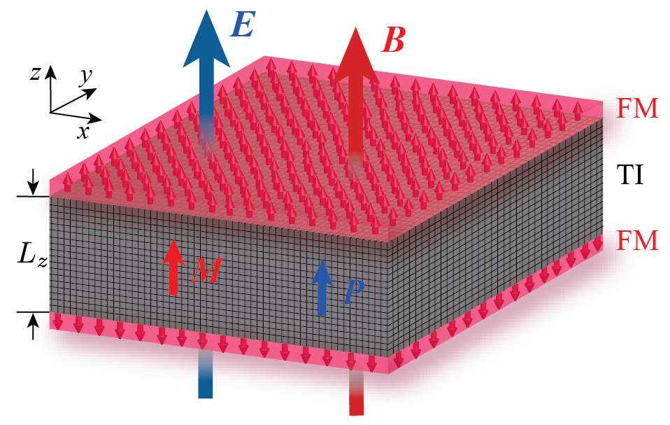
In this paper, to resolve this controversy, we study the effect of an ultrahigh magnetic field on TIs. To fully treat both bulk and surfaces, we consider the lattice Hamiltonian Zhang et al. (2009); Liu et al. (2010) for a 3D TI in a slab geometry, sandwiched between two thin ferromagnets with magnetizations pointing in the opposite directions along axis, see Fig. 1. The role of ferromagnetic films can also be played by an appropriate doping of the TI with magnetic impurities.
We first reproduce the term (1) with , in the balanced case, from the total energy of electrons. This means that the axion electrodynamics remains unchanged as long as the bulk gap is not destroyed, even though time-reversal symmetry, which plays essential role in TIs, is broken by the magnetic field. However, as the TI thickness is decreased, we observe that the ME effect starts to vanish. Based on this result, we estimate the critical thickness of TI film capable of displaying the robust ME effect, which can be useful for future experimental studies, especially in the view of recent experimental progress on TI thin films Checkelsky et al. (2012); Chang et al. (2013). Moreover, we also study the case of both strong electric and magnetic fields. We show that the response to a small change in the electric field can be characterized in this regime by different , which are still quantized as long as the Fermi level resides within the bulk gap. We show that the quantization rule of is determined by Landau level structures on the top and bottom surfaces, while the bulk states do not play an important role in thick TI films.
II Model
To study the ME effect in TIs, we employ the Wilson-Dirac tight-binding Hamiltonian for 3D lattice TI model Zhang et al. (2009); Liu et al. (2010), which is a simplified version of the effective four-band Hamiltonian for newly discovered 3D TIs such as , and Xia et al. (2009); Chen et al. (2009); Hsieh et al. (2009). We introduce external magnetic field , applied in direction, through the Peierls substitution and set its magnitude so that the magnetic flux going through a single plaquette is a rational fraction of the magnetic flux quantum. In other words, , where and are natural numbers with , is the magnetic flux quantum, and is the lattice constant. For convenience, we set in the following so the magnetic field becomes . Using Landau gauge , the Hamiltonian is defined as
| (4) |
Here, the translation operators in directions are
| (5) |
where and are the hopping parameters with and without spin flip, respectively, is the mass characterizing the spin-orbit interaction, is the lattice coordinate, is the unit lattice vector in direction, and , are the standard Dirac matrices:
where are the Pauli matrices.
To take into account the effect of an external electric field and the interaction of electron spins on TI surfaces with magnetization, we introduce additional terms and , respectively. Then, the total Hamiltonian is
| (6) | |||||
| (7) |
with the potential energy , where is the TI film thickness. The surface spin contribution Qi et al. (2008); Nomura and Nagaosa (2011); Liu et al. (2009); Abanin and Pesin (2011), see Fig. 1, is given by
| (8) |
Here, and is the surface spin constant.
III Results and Discussion
We investigate the magnetoelectric effect by calculating the energy eigenvalues of electrons. Since our model has translational invariance in and directions, Eq. (6) can be written as
| (9) |
where is matrix, see Appendix for details. By numerically performing an exact diagonalization of this Hamiltonian matrix, we solve the eigenvalue equation . The ME effect is described by the energy density of electrons:
| (10) |
where is the TI volume and is the sum of eigenvalues below the Fermi level, which is fixed at in the following. In the presence of both electric and magnetic fields, has a term as expected from the axion electrodynamics, Eq. (1).
The energy density for a typical case is plotted in the inset of Fig. 2. For fixed magnetic field, we change the electric field and plot the energy density as a function of . From Eq. (1), we estimate the parameter by , where is the slope of the linear dependence in the inset of Fig. 2. In all our calculations, we set the hopping parameters , the mass , and choose the number of layers in direction , so that the number of points in direction of the magnetic Brillouin zone is .
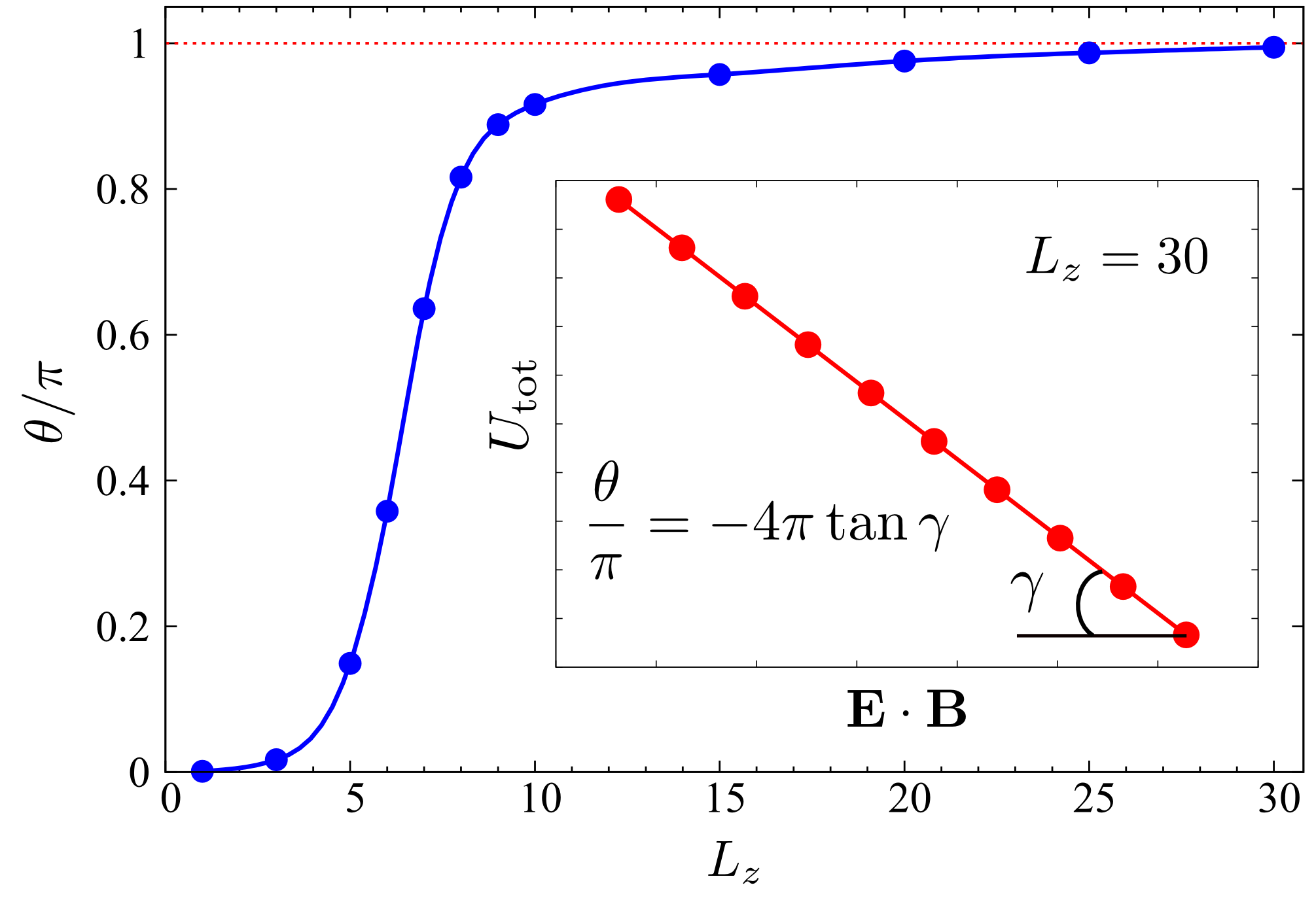
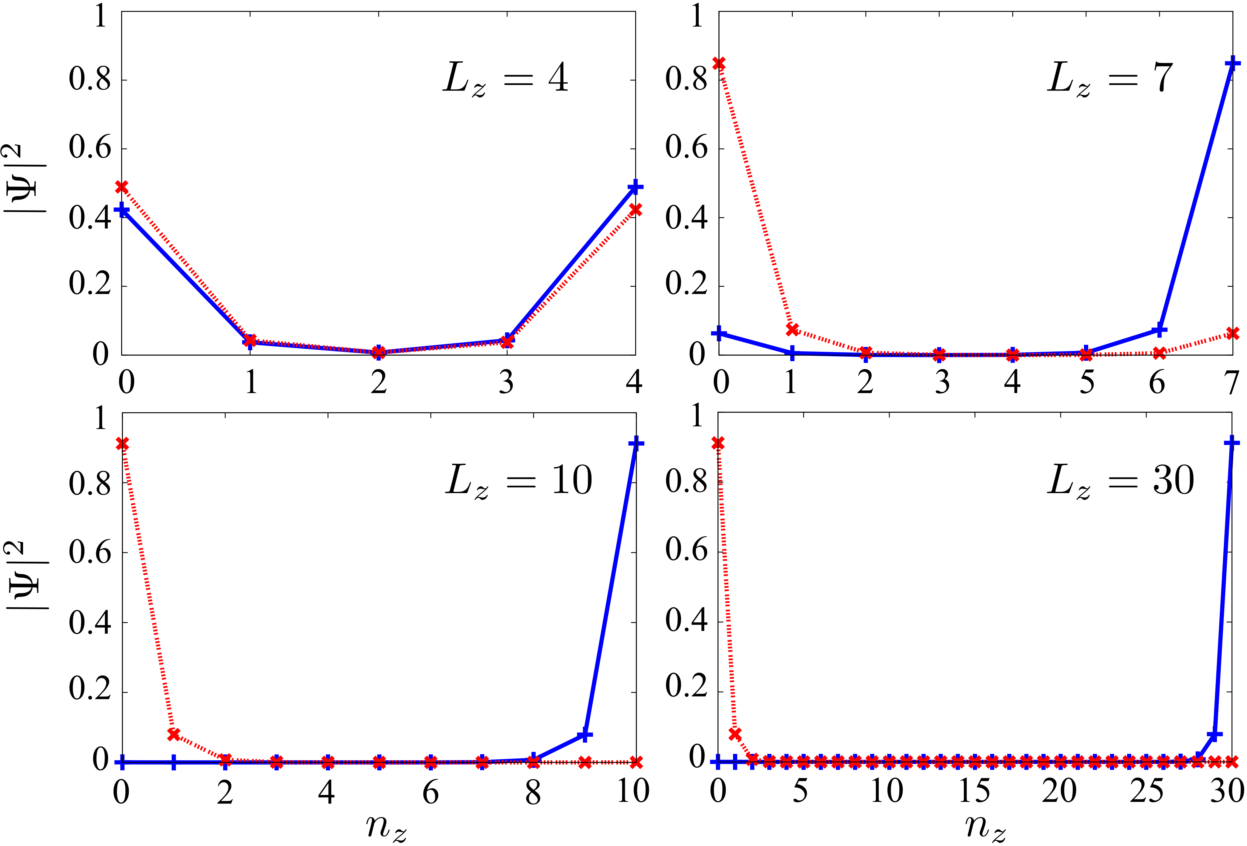
First, to verify our method, we study as a function of TI thickness for the fixed magnetic field corresponding to and , see the main panel of Fig. 2. The data show that is close to at large , whereas it decreases notably below . As approaches 1, the parameter almost vanishes, which means that in very thin TI films the ME effect disappears. When the TI thickness is very small, it is expected that its surface wave functions hybridize with each other Linder et al. (2009); Essin et al. (2009). To confirm it, we calculate the spacial profiles of the wave functions in direction for the surface states. At the point , they are calculated for several values of and shown in Fig. 3. We observe that for the wave functions are strongly localized near the TI surfaces, whereas overlap of these wave functions increases with decreasing TI thickness. At the top and bottom wave functions almost completely overlap. This clearly indicates that the reduction of the ME effect is associated with the hybridization of the surface wave functions. From Fig. 2, the value of below which the ME effect starts to significantly diminish can be estimated as . For typical TIs Cui et al. (2004); Hsieh et al. (2008); Chen et al. (2009); Xia et al. (2009); Hsieh et al. (2009), this value corresponds to nm.
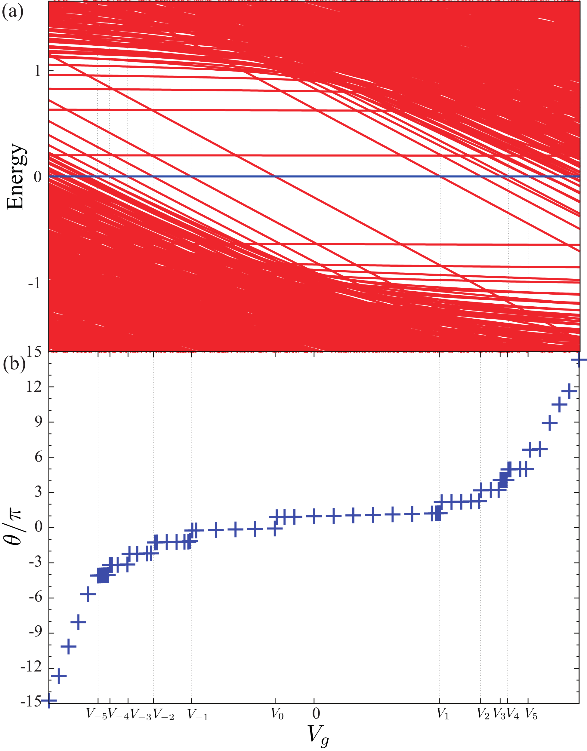
So far, we have considered a TI in a weak electric field. Experimentally, however, ultrahigh electric fields can be achieved by ionic liquid gating Checkelsky et al. (2012), and it is therefore interesting to study a nontrivial response of a TI to both strong electric and magnetic fields. In the presence of a strong magnetic field, Landau levels form on top and bottom TI surfaces. The existence of well-defined Landau levels in TIs has been confirmed by recent experimental observations of the quantum Hall effect Brüne et al. (2011); Chang et al. (2013). In our simulation, we fix for simplicity the Landau levels on the bottom surface, whereas the gating induced electric field, , shifts the energy levels on the top surface. As the gate voltage changes from , the Landau level energies on the top surface move. Figure 4(a) shows that Landau levels cross the Fermi level at the following gate voltages: . In the nonlinear regime of strong electric or magnetic fields, the axion electrodynamics corresponding to in general is not expected to be applicable. To probe this regime, we vary the electric field by small near , i. e. the total electric field is , and study the response to . Then has a role of in Eq. (1) and is defined as the overall coefficient describing the ME effect response.
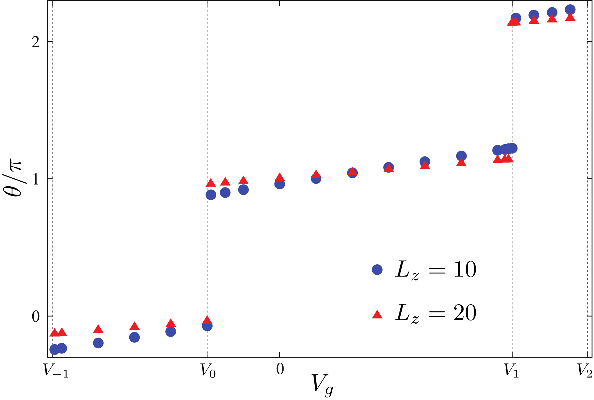
Figure 4(b) shows as a function of . One can see that there are several plateaus where is approximately quantized in integers . Every new quantization plateau in Fig. 4(b) occurs at the points where Landau levels cross the Fermi level. The exact quantization would be in agreement with the prediction of Ref. Tse and MacDonald, 2010 for weak electric fields. As we show below, the deviation from the exact quantization is mostly attributed to the asymmetry of TI surface wave functions due to the application of the large gate voltage. Thus, Fig. 4(b) shows an important fact that although time-reversal symmetry is broken in a 3D TI by a strong magnetic field, is not arbitrary as it has been claimed in Refs. Coh et al., 2011; Sitte et al., 2012, but rather quantized as long as the Fermi level is still within the bulk gap. In accord with this, the two continuous regions of the dependence in Fig. 4(b) at the left and right edges correspond to the cases when the Fermi level enters continuous (valence or conduction) bands. In the two continuous regions, however, our results only qualitatively show the behavior of the parameter , because we do not consider any screening effects coming from conduction and valence bands that may suppress the -term, and also because beyond the range bounded by and , see Fig. 4(a), there are multiple crossings of Landau levels very close to each other.
To investigate the hypothesis that the lack of exact quantization in is attributed to the asymmetry of TI surface wave functions due to gating, we repeat the same calculation for a thicker TI film. The details of the quantization of as a function of gate voltage are shown in Fig. 5 for two different TI film thicknesses. The results for are shown by blue circles and for by red triangles. At a fixed gate voltage (), applied electric field for case is two times stronger than that for . The comparison shows that when increases two times the slope of each quantization plateau becomes two times smaller. This indicates that for thick enough TI films the plateaus should become horizontal, because in this case the asymmetry of surface wave functions can be disregarded since their overlap is too small. As a result, for the thick films, depends only on the surface states, but not the bulk states. When the bulk gap is not destroyed, is determined by the surfaces and thus quantized as the Hall conductivity is quantized, i.e.,
| (11) |
where are the Landau level filling factors for the top (bottom) TI surfaces. In the case of zero applied gate voltage, , and therefore , c.f. Fig. 2.
By applying a magnetic field to the TI model, Eq. (4), we break time-reversal symmetry and as a result the system crosses from symmetry class AII, where is quantized or , to class A where in general can be arbitrary. Thus we show that depending on the perturbations (orbital or Zeeman magnetic fields or electric field), is still quantized in class A for our model. The quantization rules can be rather nontrivial depending on a combination of perturbations, however, we can successfully explain these rules based on the Landau level physics.
Finally, we study the effects of bulk magnetic interaction on the ME effect. The Zeeman type interaction between the electron spin and applied magnetic field is described by
| (12) |
where and are the effective factors depending on the TI materials. In most of cases, for materials such as Bi2Se3 and Bi2Te3, and have opposite signs Liu et al. (2010). Therefore, as a simplified model, we consider the case of . In addition, we study the influence of the exchange interaction between the electron spins and magnetic impurities that can be introduced by the appropriate doping of the TI bulk. Within the virtual crystal approximation, this interaction has the form
| (13) |
where is the exchange interaction constant and is the mean value of magnetic moments in the bulk. These two interactions, Eqs. (12) and (13), can be covered by two simple model Hamiltonians: with and being the bulk spin constant. The sign “” in indicates bulk electrons coupling with magnetization, while “” sign indicates coupling with the external magnetic field.
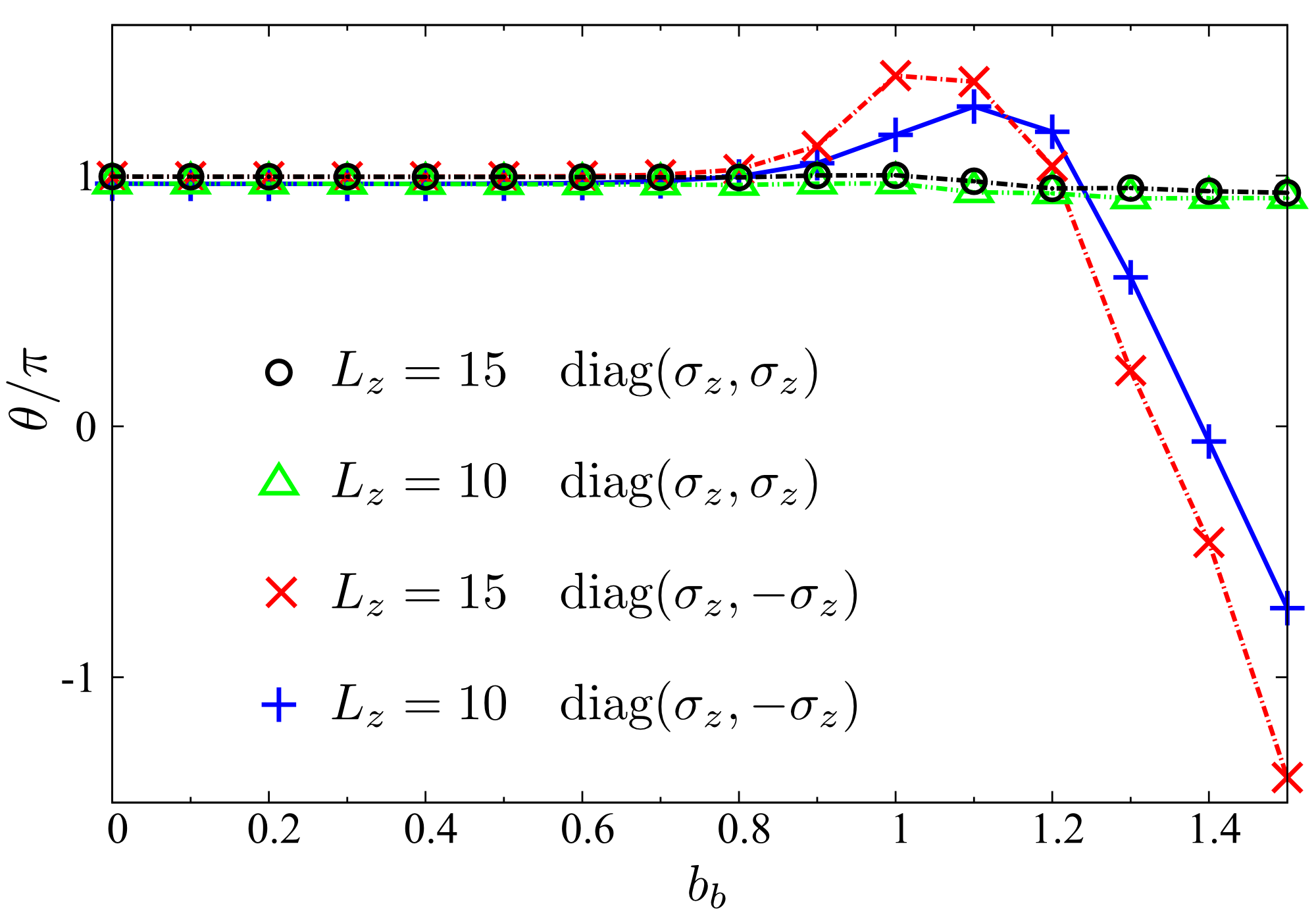
The calculation results for magnetic field are shown in Fig. 6, where the red and blue curves correspond to , red is for and blue is for . The black and green curves correspond to case, with the black for and green for . One can see from Fig. 6 that persists approximately up to , which corresponds to the TI regime. At , the system crosses to the Weyl semimetal regime Wan et al. (2011); Burkov et al. (2011) for case and therefore no quantization of beyond is expected Zyuzin and Burkov (2012). These results show remarkable robustness of the ME effect in TI phase even for very strong magnetic fields or high concentration of magnetic impurities that affect the bulk structure of the TI. It seems to be irrespective of microscopic details of coupling with the magnetic impurities or field, since it works equally well in the TI regime for the toy models with both signs.
IV Summary
We have shown that the ME effect in TIs survives even in both strong magnetic and electric fields even though time-reversal symmetry is broken. We have described the ME effect beyond the linear response regime and have confirmed that it is robust but takes a fascinating form of multiple quantization related to Landau levels crossing of the Fermi level. In addition, the influence of the TI surface hybridization has been studied in very thin TI films, describing how the ME effect vanishes in the limit of very thin TIs. Furthermore, the ME effect is shown to persist even for strong bulk interactions with magnetic field or magnetic impurities.
Acknowledgements.
We would like to thank the staff of the Center for Computational Materials Science at the IMR, Tohoku University for their support of the supercomputing facilities. K.N. was supported by Grant-in-Aid for Scientific Research (Nos. 24740211 and 25103703) from the Ministry of Education, Culture, Sports, Science and Technology (MEXT), Japan. O.A.T. acknowledges support by the Grants-in-Aid for Scientific Research (Nos. 25800184 and 25247056) from the MEXT, Japan.Appendix A APPENDIX: MODEL HAMILTONIAN IN MOMENTUM SPACE
We present below the details of diagonalization of Wilson-Dirac Hamiltonian Zhang et al. (2009); Liu et al. (2010) given by Eqs. (4) and (5) in the main text. We use a slab geometry with periodic boundary conditions in and directions and fixed boundary condition in direction, where is the number of lattice sites in direction. According to our choice of the magnetic field and Landau gauge, there is periodicity in the Aharonov-Bohm (AB) phase, i.e., the lattice sites whose coordinate is have the same AB phase. Therefore we can define a new unit cell that is times larger than the original one by introducing an additional coordinate ,
| (14) |
where is a coordinate of a one-dimensional unit cell in direction, containing lattice points and is the coordinate of the lattice site within the unit cell. As a result, the lattice can be represented by , where corresponds to a coordinate of a 3D unit cell and corresponds to a coordinate of a lattice point within that unit cell.
Because of periodicity in and directions, it is convenient to introduce a new annihilation (and corresponding creation) operator by means of Fourier transformation:
| (15) |
where and are the numbers of layers in and directions, respectively, and is the wave vector in plane. In Eq. (9) of the main text we omitted for brevity the subscript in . In terms of these operators the Hamiltonian (4) becomes
| (16) |
where and the matrix is
| (17) |
Here the diagonal block elements are
with and The nonzero off-diagonal block elements of are and , where is unit matrix.
To include the external electric field as well as surface spin interaction with magnetization terms, we apply the same transformation given by Eq. (15). Then the total model Hamiltonian, , is represented as with
| (18) |
Here the electric field and overall spin contribution coming from both TI surfaces are given by matrix with where is unit matrix.
References
- Hasan and Kane (2010) M. Z. Hasan and C. L. Kane, Rev. Mod. Phys. 82, 3045 (2010).
- Qi and Zhang (2011) X.-L. Qi and S.-C. Zhang, Rev. Mod. Phys. 83, 1057 (2011).
- Tokura (2007) Y. Tokura, J. Magn. Magn. Mater. 310, 1145 (2007).
- Qi et al. (2008) X.-L. Qi, T. L. Hughes, and S.-C. Zhang, Phys. Rev. B 78, 195424 (2008).
- Essin et al. (2009) A. M. Essin, J. E. Moore, and D. Vanderbilt, Phys. Rev. Lett. 102, 146805 (2009).
- Vazifeh and Franz (2010) M. M. Vazifeh and M. Franz, Phys. Rev. B 82, 233103 (2010).
- Nomura and Nagaosa (2011) K. Nomura and N. Nagaosa, Phys. Rev. Lett. 106, 166802 (2011).
- Tse and MacDonald (2010) W.-K. Tse and A. H. MacDonald, Phys. Rev. B 82, 161104 (2010).
- Chen and Lee (2011) K. T. Chen and P. A. Lee, Phys. Rev. B 83, 125119 (2011).
- Wilczek (1987) F. Wilczek, Phys. Rev. Lett. 58, 1799 (1987).
- Coh et al. (2011) S. Coh, D. Vanderbilt, A. Malashevich, and I. Souza, Phys. Rev. B 83, 085108 (2011).
- Sitte et al. (2012) M. Sitte, A. Rosch, E. Altman, and L. Fritz, Phys. Rev. Lett. 108, 126807 (2012).
- Essin et al. (2010) A. M. Essin, A. M. Turner, J. E. Moore, and D. Vanderbilt, Phys. Rev. B 81, 205104 (2010).
- (14) A. Malashevich, I. Souza, S. Coh, and D. Vanderbilt, New J. Phys. 12, 053032.
- Malashevich et al. (2011) A. Malashevich, D. Vanderbilt, and I. Souza, Phys. Rev. B 83, 092407 (2011).
- Zhang et al. (2009) H. Zhang, C.-X. Liu, X.-L. Qi, X. Dai, Z. Fang, and S.-C. Zhang, Nat. Phys. 5, 438 (2009).
- Liu et al. (2010) C.-X. Liu, X.-L. Qi, H. J. Zhang, X. Dai, Z. Fang, and S.-C. Zhang, Phys. Rev. B 82, 045122 (2010).
- Checkelsky et al. (2012) J. G. Checkelsky, J. Ye, Y. Onose, Y. Iwasa, and Y. Tokura, Nat. Phys. 8, 729 (2012).
- Chang et al. (2013) C.-Z. Chang, J. Zhang, X. Feng, J. Shen, Z. Zhang, M. Guo, K. Li, Y. Ou, P. Wei, L.-L. Wang, Z.-Q. Ji, Y. Feng, S. Ji, X. Chen, J. Jia, X. Dai, Z. Fang, S.-C. Zhang, K. He, Y. Wang, L. Lu, X.-C. Ma, and Q.-K. Xue, Science 340, 167 (2013).
- Xia et al. (2009) Y. Xia, D. Qian, L. Wray, A. Pal, H. Lin, A. Bansil, D. Grauer, Y. S. Hor, R. J. Cava, and M. Z. Hasan, Nat. Phys. 5, 398 (2009).
- Chen et al. (2009) Y. L. Chen, J. G. Analytis, J.-H. Chu, Z. K. Liu, S.-K. Mo, X. L. Qi, H. J. Zhang, D. H. Lu, X. Dai, Z. Fang, S. C. Zhang, I. R. Fisher, Z. Hussain, and Z.-X. Shen, Science 325, 178 (2009).
- Hsieh et al. (2009) D. Hsieh, Y. Xia, D. Qian, L. Wray, F. Meier, J. H. Dil, J. Osterwalder, L. Patthey, A. V. Fedorov, H. Lin, A. Bansil, D. Grauer, Y. S. Hor, R. J. Cava, and M. Z. Hasan, Phys. Rev. Lett. 103, 146401 (2009).
- Liu et al. (2009) Q. Liu, C.-X. Liu, C. Xu, X.-L. Qi, and S.-C. Zhang, Phys. Rev. Lett. 102, 156603 (2009).
- Abanin and Pesin (2011) D. A. Abanin and D. A. Pesin, Phys. Rev. Lett. 106, 136802 (2011).
- Linder et al. (2009) J. Linder, T. Yokoyama, and A. Sudbø, Phys. Rev. B 80, 205401 (2009).
- Cui et al. (2004) H. Cui, H. Liu, X. Li, J. Wang, F. Han, X. Zhang, and R. Boughton, J. Solid State Chem. 177, 4001 (2004).
- Hsieh et al. (2008) D. Hsieh, D. Qian, L. Wray, Y. Xia, Y. S. Hor, R. J. Cava, and M. Z. Hasan, Nature (London) 452, 970 (2008).
- Brüne et al. (2011) C. Brüne, C. X. Liu, E. G. Novik, E. M. Hankiewicz, H. Buhmann, Y. L. Chen, X. L. Qi, Z. X. Shen, S. C. Zhang, and L. W. Molenkamp, Phys. Rev. Lett. 106, 126803 (2011).
- Wan et al. (2011) X. Wan, A. M. Turner, A. Vishwanath, and S. Y. Savrasov, Phys. Rev. B 83, 205101 (2011).
- Burkov et al. (2011) A. A. Burkov, M. D. Hook, and L. Balents, Phys. Rev. B 84, 235126 (2011).
- Zyuzin and Burkov (2012) A. A. Zyuzin and A. A. Burkov, Phys. Rev. B 86, 115133 (2012).