Two-dimensional Numerical Study for Rayleigh-Taylor and Richtmyer-Meshkov Instabilities in Relativistic Jets
Abstract
We study the stability of a non-rotating single-component jet using two-dimensional special relativistic hydrodynamic simulations. By assuming translational invariance along the jet axis, we exclude the destabilization effect by Kelvin-Helmholtz mode. The nonlinear evolution of the transverse structure of the jet with a normal jet velocity is highlighted. An intriguing finding in our study is that Rayleigh-Taylor and Richtmeier-Meshkov type instabilities can destroy cylindrical jet configuration as a result of spontaneously induced radial oscillating motion. This is powered by in-situ energy conversion between the thermal and bulk kinetic energies. The effective inertia ratio of the jet to the surrounding medium determines a threshold for the onset of instabilities. The condition should be satisfied for the transverse structure of the jet being persisted.
Subject headings:
galaxies: jets — instabilities — methods: numerical — relativistic processes — shock waves1. Introduction
The persistent, well-collimated, relativistic jet is a universal structure that can be observed in the astrophysical compact object-accretion disk systems, such as active galactic nuclei (AGNs; Begelman et al., 1984; Ferrari, 1998), microquasars (Mirabel & Rodríguez, 1999), and potentially, gamma-ray bursts (GRBs; Piran, 2004; Mészáros, 2006). A grand challenge in the relativistic physics is to construct a self-consistent theory that is responsible for generation, acceleration, and collimation of the astrophysical jet.
The stability of the relativistic plasma flow is of intrinsic importance in both the acceleration and collimation mechanisms of the jet. If the plasma flow propagating relativistically through the ambient medium is unstable to internal disturbances, it should be difficult to attain the remarkable persistency and velocity of the jet expected in compact object-accretion disk systems because of the nonlinear material mixing process caused by instabilities.
The relativistic jet propagating through the ambient medium is subjected to a storm of instabilities. The shear layer, which develops spontaneously at the interface between the jet and the surrounding medium, can be destabilized by the Kelvin-Helmholtz instability (Turland & Scheuer, 1976; Blandford & Pringle, 1976). It has been investigated theoretically and numerically in the framework of the astrophysical jet (Hardee & Norman, 1988; Mizuno et al., 2007; Perucho et al., 2010), and is expected as a primary mechanism of the material mixing (Rossi et al., 2008).
In association with the magnetically driven mechanism for the jet-launching (Blandford & Payne, 1982; Uchida & Shibata, 1985; Shibata & Uchida, 1986), the stability of the magnetized jet is one of the front line topics in relativistic physics. The poynting flux-dominated jets carrying large-scale helical magnetic fields can become unstable to the kink mode of the current-driven (CD) instability (Lundquist, 1951; Spruit et al., 1997; Begelman, 1998).
A pioneering numerical work done by Mizuno et al. (2009) investigated the CD kink instability for a static force-free equilibrium by three-dimensional (3D) general relativistic magnetohydrodynamic (MHD) simulation (see also Baty & Keppens 2002 for the case of non-relativistic MHD). However, it is still a matter of debate whether the CD kink instability is essential for the astrophysical jet because the 3D configuration and strength of the magnetic field, which are deeply related to the launching mechanism, are veiled in mystery.
One of few works that studies the effect of the Rayleigh-Taylor instability (RTI; Rayleigh, 1900; Taylor, 1950) on the jet dynamics is Meliani & Keppens (2007, 2009). They performed 2.5 dimensional numerical simulations of two-component jet consisting of a fast inner spine and a slower outer flow. They found that the rotational shear that develops at the interfaces between the spine and sheath, and the sheath and ambient, plays a key role in triggering the RTI in the two-component jet. The driving force of the RTI is, in this case, the centrifugal force.
Even without the rotation, the relativistic jet potentially becomes unstable to the RTI. A radial inertia force naturally arises from a pressure mismatch between the jet and surrounding medium when the jet propagates through the ambient medium. The inertia force drives the radial oscillating motion of the jet, yielding the reconfinement region inside the jet (e.g., Gomez et al., 1997; Matsumoto et al., 2012). When considering the non-axisymmetric evolution of the jet, it might excite the RTI at the interface of the jet (see also §3.1).
In this Letter, the nonlinear development of the relativistic jet is studied using special relativistic hydrodynamic (SRHD) simulations. By assuming a non-rotating single component jet with translational invariance along the jet axis, the two-dimensional stability of the transverse structure of the jet to the radial oscillation-induced RTI is investigated.
| Model | ||||||||
|---|---|---|---|---|---|---|---|---|
| A1 | 0.99 | 7 | 147 | |||||
| A2 | 0.99 | 7 | 1 | 10 | ||||
| A3 | 0.99 | 7 | 1 | 1 | ||||
| A4 | 0.99 | 7 | 1 | 0.1 | ||||
| B1 | 0.99 | 7 | 1 | 57 | ||||
| B2 | 0.99 | 7 | 1 | 6 | ||||
| B3 | 0.99 | 7 | 1 | 0.6 | ||||
| B4 | 0.99 | 7 | 1 | 0.06 | ||||
| C1 | 0.99 | 7 | 1 | 68 | ||||
| C2 | 0.99 | 7 | 1 | 7 | ||||
| C3 | 0.99 | 7 | 1 | 0.7 | ||||
| C4 | 0.99 | 7 | 1 | 0.07 | ||||
| D1 | 0.99 | 7 | 1 | 52 | ||||
| D2 | 0.99 | 7 | 1 | 5 | ||||
| D3 | 0.99 | 7 | 1 | 0.5 | ||||
| D4 | 0.99 | 7 | 1 | 0.05 |
2. Numerical Method
2.1. Basic Equations
We numerically solve the nonlinear development of a single-component relativistic jet in a cylindrical coordinate system . By dropping derivatives of the physical variables in the z-direction, we exclude the destabilization effect of the Kelvin-Helmholtz instability that can grow along the jet direction. We focus simply on the stability of the transverse structure of the jet to the non-axisymmetric perturbations. Assuming an ideal gas law with a ratio of specific heats , the basic equations are the two-dimensional SRHD equations:
| (1) | |||||
| (2) | |||||
| (3) | |||||
| (4) | |||||
| (5) | |||||
where is the Lorentz factor and is the specific enthalpy. The other symbols have their usual meanings.
A relativistic HLLC scheme is used to solve the SRHD equations (1)–(5) (Mignone & Bodo, 2005). The primitive variables are calculated from the conservative variables following the method of Mignone & McKinney (2007). We use a MUSCL-type interpolation method to attain second-order accuracy in space while the temporal accuracy obtains second-order by using Runge-Kutta time integration. See Matsumoto et al. (2012) for more detail on our SRHD code.
The initial rest mass energy density of the external medium and the initial jet velocity are common parameters for all the models we studied, and are assumed as and , respectively. The initial Lorentz factor of the jet is then evaluated as . We have three control parameters in our simulations, the initial rest mass energy density of the jet (), the initial pressure of the jet (), and the initial pressure of the external medium (). The fiducial model (Model A1 in Table 1) adopts , and . Note that the jet is initially assumed to be overpressured for all the models.
The normalization units in length, velocity, time, and energy density are chosen as the initial jet radius , light speed , light crossing time over the initial jet radius , and rest mass energy density in the external medium . We use a uniformly spaced grid in cylindrical coordinates consisting of zones in - and -directions. The computational domain spans and . The initial jet radius is resolved by numeric cells. An outflow (zero gradient) boundary condition is imposed on the outer boundary of the domain. The coordinate singularity is treated by placing no grid point on the cylindrical axis and filling appropriate ”ghost grids” in the region (See, Mohseni & Colonius 2000 and Ghosh et al. 2010 for the treatment of the coordinate singularity with using ghost grids). A separate longer paper will provide our treatment of the singular point and its implementation to the HLLC scheme in more detail. By introducing small-amplitude () random pressure perturbations to the initial configuration, the simulation is initiated.
3. Results
3.1. A Basic Physics Governing Oscillating Motion of Jet
Here, to aid understanding of our numerical results, we briefly describe the basic physics governing the radial jet oscillation, which naturally arises from the pressure difference between the jet and the external medium. See Matsumoto et al. (2012) for more detail of the radial oscillating motion of the jet in the axisymmetric model.
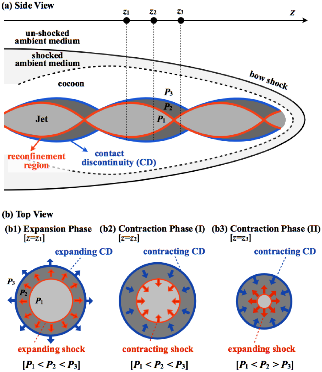
Figure 1(a) schematically depicts the traditional picture of the relativistic jet propagating through the ambient medium. The ambient medium is thermalized at the jet head during the jet propagation, and simultaneously forms a cocoon. This is the reason the jet is surrounded by the enveloped cocoon material. The transverse structures of the jet on cutting planes at , and are shown in panels (b1)–(b3), respectively. The region enclosed by a red curve is the reconfinement region. The blue curve denotes the contact discontinuity that separates the jet from the surrounding medium.
Since the jet is initially overpressured in our model, it starts to expand adiabatically in the radial direction (panel (b1)). The adiabatic cooling leads to in-situ energy conversion between the thermal and bulk kinetic energies of the jet according to the relativistic Bernoulli’s principle (). The gas pressure inside the jet thus becomes smaller than that of surroundings in the expansion phase. The expansion is then decelerated by the inward pressure-gradient force acting on the jet-surrounding medium interface, and is finally turned into the contraction (panel (b2)). In the subsequent phase, the pressure inside the jet increases with the contraction of the jet (panel (b3)). The jet restarts to expand radially when the gas pressure of the jet becomes larger than that of the surrounding medium.
During the radial oscillation of the jet, the reconfinement region enclosed by a shock surface is formed inside the jet (Norman et al., 1982; Sanders, 1983). As shown in Figure 1(a), the shock-shock collision at the center of the jet excites the outward-propagating shock. The collision between the shock and the contact discontinuity results in the contracting reconfinement shock. The transition between the outward- and inward-propagating shocks occurs repeatedly and shapes the reconfinement region.
The radial pressure mismatch between the jet and surrounding medium assumed in our initial setting is a modeling to reproduce this radial jet oscillation already established in axisymmetric models (Daly & Marscher, 1988; Matsumoto et al., 2012). The restoring force of the jet oscillation, which is obviously the pressure gradient force acting on the jet-surrounding medium interface, might induce the RTI when we consider the non-axisymmetric evolution of the jet.
3.2. Time Evolution of the Fiducial Model
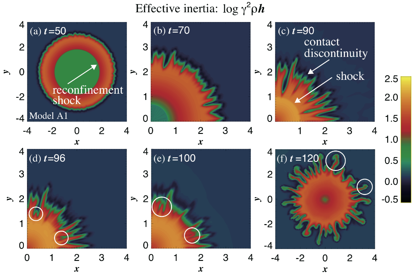

Shown sequentially in Figures 2(a)–(f) is the temporal evolution of the cross section of the jet for the fiducial model (Model A1 in Table 1). The snapshots (a)–(f) represent the transverse distribution of the effective inertia at , and , respectively. Figure 2(g) shows the temporal evolution of the volume–averaged azimuthal velocity defined by,
| (6) |
The solid line denotes the fiducial model. The filled circles indicate at the time corresponding to the snapshots (a)–(f).
The development of the RTI at the interface separating two fluids is controlled by the difference in the inertia of the fluid gases in the non-relativistic regime. In the relativistic regime where the internal energy of the gas is comparable to or greater than its rest mass energy and/or the fluid velocity is relativistic, the inertia of the fluid is enhanced by relativistic effects. The effective inertia is thus a good indicator for studying the gas dynamics, especially the stability. Note that the effective inertia of the jet is larger than the external medium although the density of the jet is smaller than the external medium in the fiducial model.
In Figure 2(a), the inward-propagating reconfinement shock is formed behind the corrugated contact discontinuity that separates the jet and the external medium. One can find that the amplitude of the corrugated jet–external medium interface grows as time passes (Figures 2(a)–(c)). Then a finger-like structure, which is a typical outcome of the RTI, emerges in Figure 2(c). The RTI is induced by inward pressure gradient force.
The convergence of the inward-propagating reconfinement shock produces an outward-spreading shock at the center of the jet. At the timing when the outward going shock collides with the contact discontinuity, the Richtmeier-Meshkov instability (RMI; Richtmyer, 1960; Meshkov, 1969) is secondarily excited between RTI fingers. See Figure 2(d) for the excitation of the RMI fingers that are marked by open circles (this process can be clearly seen in the online animation). The evolution of the RMI-driven finger marked by the white circle in Figure 2(d) is tracked in Figures 2(e) and (f). We stress that almost all finger-like structures in Figure 2(f) have their origin in the RMI.
During the radial oscillating motion of the jet, the two types of finger structures are amplified and repeatedly excited at the contact discontinuity, and finally deform the transverse structure of the jet. The fiducial model indicates that the transverse structure of the jet is dramatically deformed by a synergetic growth of the RTI and RMI once the jet-external medium interface is corrugated in the case with the pressure-mismatched jet.
The synergetic growth of the RTI and RMI can be confirmed in Figure 2(g). The volume-averaged azimuthal velocity increases exponentially until after . This is due to the RTI that grows at the jet-external medium interface. At around the time when the outgoing shock passes through the contact discontinuity, the evolution property of the is dramatically changed, linearly increasing in time. This is evidence of the excitation of the RMI because it is well-known that the perturbation amplitude grows linearly with time when the RMI develops (Richtmyer 1960; Nishihara et al. 2010). After , the system enters into the nonlinear saturation stage.
3.3. Stability Condition of Jet
The condition for the transverse structure of the jet being maintained is studied by varying two physical parameters that characterize the jet-external medium system. We focus on the initial effective inertia ratio between the jet and external medium, which is defined by
| (7) |
and the initial specific enthalpy of the jet which is a good indicator whether the gas is relativistically hot. The model parameters surveyed for examining the jet stability are summarized in Table 1 (Models A1–D4). With the same physical and computational settings except the parameters and , we simulate various jet-external medium systems.
In the following, the ”unstable model” corresponds to the model in which the transverse structure of the jet is deformed in the same way as the fiducial model. In contrast, the ”stable model” means that the transverse structure of the jet is maintained. As an example of the stable model, the temporal evolution of the for Model A4 is demonstrated by a dashed line in Figure 2(g). The RTI and RMI are suppressed and the jet interface does not deform in the stable model.
Figure 3 presents the stability diagram for the transverse structure of the jet in the – parameter space. The vertical axis shows . The cross and open circle indicate the unstable and stable models, respectively. One finds that the stability criterion of the jet can be simply written as regardless of the specific enthalpy of the jet. The jet can maintain its transverse structure as long as the effective inertia of the jet is smaller than that of the ambient when excluding the destabilization effects by the Kelvin-Helmholtz mode.

4. Summary and Discussion
In this Letter, the stability of the transverse structure of the non-rotating single-component relativistic jet was studied using SRHD simulations. The nonlinear evolution of the non-axisymmetric perturbation in the two-dimensional – plane was highlighted by assuming a translational invariance along the jet axis.
Initial pressure mismatch between the jet and surrounding medium results in the radial oscillating motion of the jet. An intriguing finding in our study is that the inertia force, which acts as a restoring force of the radial oscillating motion, triggers the primary RTI and the secondary RMI at the jet-external medium interface. The transverse structure of the jet is remarkably deformed by the nonlinear growth of these radial oscillation-induced instabilities.
The condition for the transverse structure of the jet being maintained is written, regardless of the specific enthalpy of the jet, as , where is the effective inertia ratio of the jet to the external medium. This suggests that the inertia ratio between the jet and enveloped cocoon material is a critical parameterin a realistic situation, as illustrated in figure 1(a), to evaluate the stability of the relativistic jet to the oscillation-induced RTI and RMI.
The condition for the growth of the radial oscillation-induced RTI is the same as that for the centrifugally driven RTI found in Meliani & Keppens (2009). This simply indicates that a contact discontinuity separating two fluids with becomes unstable to the RTI regardless of the origin of the driving force. Unlike the RTI, the growth of the RMI at the jet-surrounding medium interface has not been reported in Meliani & Keppens (2009) and the other previous studies. The synergetic growth of the RTI and RMI, which is a characteristic feature in our unstable model, enhances the deformation of the jet interface.
The growth of the RMI is essentially due to the pressure-mismatched jet that is assumed in our initial setting. This induces the radial oscillating motion of the jet and, additionally, the RMI at the jet-surrounding medium interface. Meliani & Keppens (2009) adopts the initial condition where the radial pressure balance is established in the calculation domain. This would be the main reason the RMI does not grow in their work.
A lot of previous 2D axisymmetric studies suggest that the formation and oscillation of the reconfinement shock is a natural result of the jet propagation through the ambient medium and is a key to attain the remarkable collimation and persistency of the jet (e.g., Marti et al., 1997; Morsony et al., 2007; Mizuta & Aloy, 2009). However, an important message from our simulations is that the non-axisymmetric nature is essential for the stability of the relativistic jet to the oscillation-induced instabilities. They would have a great impact on the collimation and the acceleration of the three-dimensional jet propagating through ambient medium. The high-resolution realistic 3D simulation of the jet propagation is within the scope of our work and will be reported in our subsequent paper.
Appendix A Ability of HLLC and HLL Schemes to Simulate Instabilities
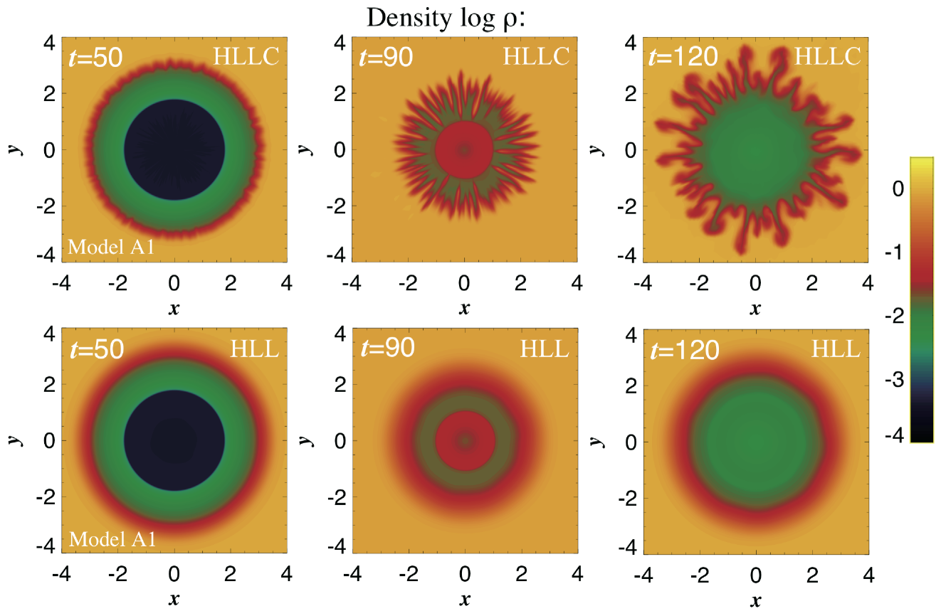
The evolution of the RTI and RMI was simulated in this Letter. To capture these instabilities, a numerical scheme capable of accurately resolving a contact discontinuity is required. In our simulations, we use a relativistic HLLC scheme (Mignone & Bodo, 2005), which is a modification of the HLL scheme (Harten et al., 1983) by restoring the missing contact wave in the solution of the Riemann problem. Here we shed light on the ability of the HLL and HLLC schemes to simulate these instabilities using codes developed by Matsumoto et al. (2011) and Matsumoto et al. (2012), respectively.
Figure 4 shows the temporal evolution of the cross section of the jet for the fiducial model (Model A1 in Table 1). The upper and lower panels place, in order of time, results obtained in models evolved by HLLC and HLL schemes, respectively. It is surprising that the RTI and RMI fingers do not emerge in the model with HLL scheme although the completely same initial settings and grid spacings ( zones in and directions) are adopted in both models. With our simulation codes, three times higher resolution is needed to capture the RTI and RMI in the HLL scheme than in the HLLC scheme.
References
- Baty & Keppens (2002) Baty, H., & Keppens, R. 2002, ApJ, 580, 800
- Begelman et al. (1984) Begelman, M. C., Blandford, R. D., & Rees, M. J. 1984, Reviews of Modern Physics, 56, 255
- Begelman (1998) Begelman, M. C. 1998, ApJ, 493, 291
- Blandford & Pringle (1976) Blandford, R. D., & Pringle, J. E. 1976, MNRAS, 176, 443
- Blandford & Payne (1982) Blandford, R. D., & Payne, D. G. 1982, MNRAS, 199, 883
- Daly & Marscher (1988) Daly, R. A., & Marscher, A. P. 1988, ApJ,334, 539
- Ferrari (1998) Ferrari, A. 1998, ARA&A, 36, 539
- Ghosh et al. (2010) Ghosh, S., Foysi, H., & Friedrich, R. 2010, Journal of Fluid Mechanics, 648, 155
- Gomez et al. (1997) Gomez, J. L., Marti, J. M. A., Marscher, A. P., Ibanez, J. M. A., & Alberdi, A. 1997, ApJ, 482, L33
- Hardee & Norman (1988) Hardee, P. E., & Norman, M. L. 1988, ApJ, 334, 70
- Harten et al. (1983) Harten, A., Lax, P.D., & van Leer, B. 1983, SIAM Rev. 25, 35
- Lundquist (1951) Lundquist, S. 1951, Physical Review, 83, 307
- Marti et al. (1997) Marti, J. M. A., Mueller, E., Font, J. A., Ibanez, J. M. A., & Marquina, A. 1997, ApJ, 479, 151
- Matsumoto et al. (2011) Matsumoto, J., Masada, Y., Asano, E., & Shibata, K. 2011, ApJ, 733, 18
- Matsumoto et al. (2012) Matsumoto, J., Masada, Y., & Shibata, K. 2012, ApJ, 751, 140
- Meliani & Keppens (2007) Meliani, Z., & Keppens, R. 2007, A&A, 475, 785
- Meliani & Keppens (2009) Meliani, Z., & Keppens, R. 2009, ApJ, 705, 1594
- Meshkov (1969) Meshkov, E. E. 1969, Fluid Dyn., 4, 101
- Mészáros (2006) Mészáros, P. 2006, Reports on Progress in Physics, 69, 2259
- Mignone & Bodo (2005) Mignone, A., & Bodo, G. 2005, MNRAS, 364, 126
- Mignone & McKinney (2007) Mignone, A., & McKinney, J. C. 2007, MNRAS, 378, 1118
- Mirabel & Rodríguez (1999) Mirabel, I. F., & Rodríguez, L. F. 1999, ARA&A, 37, 409
- Mizuno et al. (2007) Mizuno, Y., Hardee, P., & Nishikawa, K.-I. 2007, ApJ, 662, 835
- Mizuno et al. (2009) Mizuno, Y., Lyubarsky, Y., Nishikawa, K.-I., & Hardee, P. E. 2009, ApJ, 700, 684
- Mizuta & Aloy (2009) Mizuta, A., & Aloy, M. A. 2009, ApJ, 699, 1261
- Mohseni & Colonius (2000) Mohseni, K., & Colonius, T. 2000, Journal of Computational Physics, 157, 787
- Morsony et al. (2007) Morsony, B. J., Lazzati, D., & Begelman, M. C. 2007, ApJ, 665, 569
- Nishihara et al. (2010) Nishihara, K., Wouchuk, J. G., Matsuoka, C., Ishizaki, R., & Zhakhovsky, V. V. 2010, Royal Society of London Philosophical Transactions Series A, 368, 1769
- Norman et al. (1982) Norman, M. L., Winkler, K.-H. A., Smarr, L., & Smith, M. D. 1982, A&A, 113, 285
- Piran (2004) Piran, T. 2004, Reviews of Modern Physics, 76, 1143
- Perucho et al. (2010) Perucho, M., Martí, J. M., Cela, J. M., et al. 2010, A&A, 519, A41
- Rayleigh (1900) Rayleigh, L. 1900, Scientific Papers, Vol. II (Cambridge: Cambridge Univ. Press), 200
- Richtmyer (1960) Richtmyer, R. D. 1960, Commun. Pure Appl. Math., 13, 297
- Rossi et al. (2008) Rossi, P., Mignone, A., Bodo, G., Massaglia, S., & Ferrari, A. 2008, A&A, 488, 795
- Sanders (1983) Sanders, R. H. 1983, ApJ, 266, 73
- Shibata & Uchida (1986) Shibata, K., & Uchida, Y. 1986, PASJ, 38, 631
- Spruit et al. (1997) Spruit, H. C., Foglizzo, T., & Stehle, R. 1997, MNRAS, 288, 333
- Taylor (1950) Taylor, G. 1950, Royal Society of London Proceedings Series A, 201, 192
- Turland & Scheuer (1976) Turland, B. D., & Scheuer, P. A. G. 1976, MNRAS, 176, 421
- Uchida & Shibata (1985) Uchida, Y., & Shibata, K. 1985, PASJ, 37, 515