-Symmetric Plasmonic Metamaterials
Abstract
We theoretically investigate the optical properties of parity-time (PT) symmetric three-dimensional metamaterials composed of strongly-coupled planar plasmonic waveguides. By tuning the loss-gain balance, we show how the initially isotropic material becomes both asymmetric and unidirectional. Investigation of the band structure near the material’s exceptional point reveals several intriguing optical properties, including double negative refraction, Bloch power oscillations, unidirectional invisibility, and reflection and transmission coefficients that are simultaneously equal to or greater than unity. The highly tunable optical dispersion of -symmetric metamaterials provides a foundation for designing an entirely new class of three-dimensional bulk synthetic media, with applications ranging from lossless sub-diffraction-limited optical lenses to non-reciprocal nanophotonic devices.
Textbook conceptions of light-matter interactions have been challenged by two recent material advances — the development of metamaterials and the discovery of parity-time -symmetric media. Metamaterials allow considerable control over the electric and magnetic fields of light, so that permittivities, permeabilities, and refractive indices can be tuned throughout positive, negative, and near-zero values. Metamaterials have enabled negative refraction, optical lensing below the diffraction limit of light and invisibility cloaking Valentine et al. (2008); Yao et al. (2008); Zhang et al. (2008, 2009); Atre et al. (2013); Xu et al. (2013); Shalaev (2007); Soukoulis and Wegener (2011); Lezec et al. (2007). Complementarily, -symmetric media allow control over electromagnetic field distributions in loss and gain media, so that light propagation can be asymmetric and even unidirectional. -symmetric media have enabled loss-induced optical transparency, lossless Talbot revivals and unidirectional invisibility Benisty et al. (2011); Guo et al. (2009); Ramezani et al. (2012); Makris et al. (2010); Zheng et al. (2010); Longhi (2011); Rüter et al. (2010); Lin et al. (2011); Mostafazadeh (2013); Feng et al. (2013); Makris et al. (2008); G.Castaldi et al. (2013). Combined with non-linear media, they have also been suggested as optical diodes, insulators, circulators, and perfect cavity absorber-lasers Musslimani et al. (2008); Lazarides and Tsironis (2013); Li et al. (2012); He et al. (2011); Dmitriev et al. (2010); Chong et al. (2011); Longhi (2010).
While metamaterials rely on subwavelength engineered ‘building blocks’ to control electric and magnetic light-matter interactions, -symmetric media rely on judicious spatial arrangement of loss and gain media. Their unique asymmetric properties are based on a fundamental insight from quantum mechanics indicating that Hamiltonians need not be Hermitian to yield real eigenvalues and hence physical observables. Instead, the weaker condition of parity and time symmetry is sufficient to yield real eigenvalues below a certain threshold. Above this threshold, eigenvalues move into the complex plane and become complex conjugates of each other Bender et al. (1999); Bender (2007); Ahmed (2001); Bender and Boettcher (1998); Mostafazadeh (2002).
In the context of optics, -symmetric Hamiltonians arise from the duality between the quantum mechanical Schrodinger equation and the wave equation. Provided the refractive index profile satisfies , light will propagate as if it experiences a -symmetric potential. Below the -symmetric exceptional point, the optical eigenvalues will be purely real; however, as the loss and gain of the material are increased beyond the exceptional point, the eigenvalues will become complex. In particular, certain eigenmodes will experience increased loss while other eigenmodes will exhibit strong optical gain. This behavior is at the core of the asymmetric and unidirectional optical properties observed in media to date.
While nearly all -symmetric media have been constructed from macroscopic (i.e., greater than wavelength-scale) elements, the optical Hamiltonian places no restrictions on the length scales over which the index profile can vary. This insight drives the question: can we create -symmetric metamaterials — i.e., bulk photonic media whose optical properties are determined both by their subwavelength building blocks and a judicious choice of their loss/gain profile? Such metamaterials would enable unprecedented control over electric and magnetic optical fields across wavelength and subwavelength scales, and may enable an entirely new class of bulk synthetic photonic media.
In this Letter, we investigate the emergent optical properties of bulk, three-dimensional -symmetric metamaterials. As a prototype metamaterial, we consider a multilayer stack of alternating layers of metal and dielectric. Both theoretical Verhagen et al. (2010) and experimental Xu et al. (2013) work has demonstrated the isotropic negative index response of this metamaterial, resulting in all-angle negative refraction and Veselago ‘perfect optical lensing.’ Its operation is based on the negative index plasmonic modes of its unit cell — a five-layer ‘metal-insulator-metal’ waveguide. By varying the thickness of the layers as well as the materials, the frequency of operation and the emergent bulk index of refraction can be precisely controlled throughout optical frequencies. While practical utilization of this negative index metamaterial has been limited by propagation and coupling losses, we will show that these losses could be overcome by subjecting the plasmonic modes to -symmetric potentials. Moreover, -symmetric potentials in this metamaterial can enable above-unity transmission and reflection, Bloch power oscillations, hyperbolic to elliptic dispersion transitions, and unidirectional invisibility.
Figure 1a illustrates the specific plasmonic metamaterial investigated in this paper, with the unit cell period indicated by . Within each unit cell, the thicknesses of the metal and dielectric are deeply subwavelength, with = = 30 nm. We consider Ag as the metal, described by a lossless Drude model with dielectric constant 111Here we assume a lossless Drude model, but the results are generalizable to a realistic case including loss. See for example reference Benisty et al. (2011). The bulk plasma frequency of Ag, , is assumed to be s-1. We consider the dielectric layers to be TiO2 with n = 3.2. With these materials, the surface plasmon resonance, , occurs at 1.73 eV , and negative index modes are observed between this frequency and . This particular materials combination was recently experimentally shown to exhibit all-angle negative refraction and Veselago lensing Xu et al. (2013). Here, we theoretically investigate the evolution of the optical bands of this metamaterial upon varying the imaginary part of the refractive index of TiO2, denoted as k in Fig.1. -symmetric potentials require balanced loss and gain, so the magnitude of this ‘non-Hermiticity parameter’, k, is identical for alternating dielectric layers.
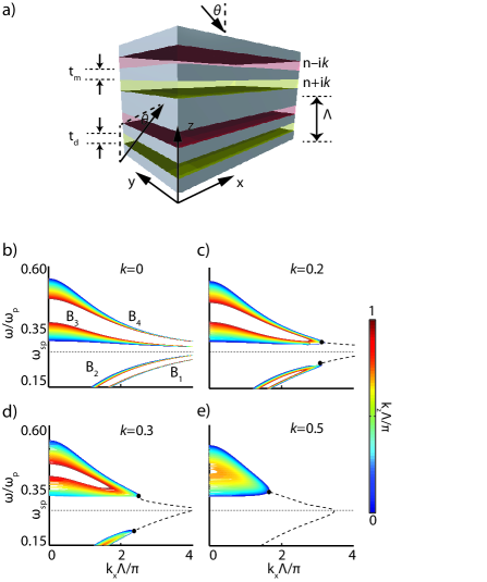
Using the transfer matrix approach described in Russell et al. (1995), we solve for the dispersion curves of the five-layer unit-cell plasmonic waveguide for transverse-magnetic (TM) polarized illumination. To determine the band diagrams of the periodic metamaterial, the wavevector along the z-direction is swept in the first Brillouin zone, , and the characteristic equation is minimized to find the propagation constant along the x-direction at each frequency. The results are shown in panels (b)-(e) of Fig. 1 for k = 0, 0.2, 0.3 and 0.5, respectively. Note that the colormap indicates purely real values of , corresponding to lossless propagation along the metamaterial. For a non-Hermiticity parameter k = 0, four different branches are observed: two below (B1 and B2) and two above (B3 and B4). Because all constituents are lossless, the wavevectors diverge at . B1 and B2 are characterized by positive slopes and hence positive refractive mode indices. In contrast, B3 and B4 are characterized by negative slopes and hence negative refractive mode indices.
When the non-Hermiticity parameter of the metamaterial is increased, the modes merge together at the exceptional points of the dispersion, denoted by black circles in panels (c)-(e). Beyond these exceptional points, the two distinguishable lossless modes below and above (i.e., B1 and B2 or B3 and B4, respectively) evolve to a gain mode and a loss mode with the same phase velocity. Due to their complex wavevectors, we denote these modes as black, dashed lines in Fig. 1(c)-(e). To understand these loss and gain modes, note that the transfer matrix of the -symmetric metamaterial possesses the following symmetry property:
| (1) |
where I is the identity matrix. The Bloch modes of the metamaterial are eigenvalues of T and satisfy:
| (2) |
Taking the complex conjugate of Eq. 2 and using the symmetry property of Eq. 1, the following relation is obtained:
| (3) |
Equation 3 means that if (a complex number in general) admits a real solution for the Bloch wavevector, is a solution for that Bloch mode as well. Accordingly, the bands have centro-symmetry in the complex plane. Also note that the loss and gain modes of Fig. 1 (c)-(e) conjoin at ; further, unlike the modes for a zero non-Hermiticity parameter, their wavevectors at remain finite.
While real periodic spatial refractive index profiles lead to the appearance of an infinite number of band gaps, complex periodic index profiles generally result in complex dispersion curves across the entire frequency range. Interestingly, if the refractive index profile satisfies the condition for symmetry () real propagation constants and complete band gaps can exist provided . Here, is the threshold value at which the Hamiltonian and the operator no longer commute, and consequently, real-valued solutions cease to be supported by the complex potential. Fig. 1 (c)-(e) illustrate this feature for increasing non-Hermiticity parameter. For example, for k = 0.2 and k = 0.3 purely real wavevectors and bandgaps are observed for all bands both above and below . However, for k = 0.5, purely real eigenmodes below do not exist across visible and near-infrared frequencies. Further, the bandgap between and merges for large , and these bands only exist over a very limited wavevector and wavelength range.
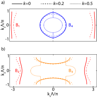
The non-Hermiticity parameter not only changes the propagation constant and bandgap of the metamaterial, but also the band curvature. Fig. 2 plots the equi-frequency contours of bands - at wavelengths of nm () for and , nm () for , and nm () for . Since the metamaterial is isotropic in the xy-plane and the contours are centro-symmetric in the plane, a quadratic dispersion relation can be used to model the bands. Here indicates the free-space wavevector. The fitted refractive mode indices are listed in Table 1.
| k = 0 | k = 0.2 | k = 0.5 | |
|---|---|---|---|
| , | , | , | |
| (95.86 , 289.89) | (85.5 , 53.56) | NA | |
| (54.14 , 58.86) | (59.32 , 24.83) | NA | |
| (4.11 , 1.27) | (4.88 , 1.21) | (11.55 , 1.16) | |
| (1.9 , 1.85) | (1.85 , 1.45) | (1.02 , 0.66) |
As seen both in Fig. 2 and Table 1, for a non-Hermiticity parameter k = 0, bands and are elliptical (i.e., 0) while bands and are hyperbolic (i.e., 0). Moreover, is characterized by a nearly-perfect circular equi-frequency contour and almost equal values of effective refractive indices in both the x and z-directions. Accordingly, this metal-insulator-metal metamaterial is isotropic at = 445 nm, consistent with prior work Verhagen et al. (2010); Xu et al. (2013).
For increasing non-Hermiticity parameter, and remain elliptical while remains hyperbolic. Interestingly, however, band undergoes a hyperbolic to elliptical transition for k = 0.5. Such hyperbolic-to-elliptic transitions could enable dynamic tuning of Purcell enhancements for emitters near the metamaterial. Further, they could modulate Talbot revivals or the formation and resolution of images generated by hyperbolic metamaterial super-lenses Ni et al. (2011); Jacob et al. (2012); Webb and Yang (2006); Kim et al. (2012); Zhao et al. (2011).
The results of Fig. 2 imply that with increasing non-Hermiticity parameter, the material can evolve from an isotropic metamaterial to an anisotropic one. Intriguingly, the structure can also become highly directional. This property cannot be derived from the band diagrams, but can be understood by considering the transfer matrix:
| (4) |
Here, the parameters , and are related to the reflection and transmission coefficients and as , and , where the subscripts L and R denote illumination from the left and right, respectively. As these equations indicate, an optical system composed of linear and reciprocal materials is non-directional provided the components are lossless. In other words, the transmitted and reflected powers and sum to unity and are independent of illumination direction, since and , so . When loss or gain is introduced into the system, the transmission coefficient remains the same for both directions of illumination. However the reflection coefficient need not be symmetric, as power can be attenuated or generated within the structure. The asymmetry is obtained at the price of losing propagating Bloch modes. However, as we will show, asymmetric responses can be obtained in a -symmetric potential where purely real bands exist as well.
To illustrate this directional behavior, Fig. 3 plots plane-wave refraction of light from vacuum () through a metamaterial composed of 10 unit cells. We consider TM-polarized illumination of wavelength = 445 nm impinging on the metamaterial at an angle of = 45∘ in the plane. The colormap of Fig. 3 plots the component of the fields. The arrows of Fig. 3 indicate the direction of illumination, refraction and transmission, each determined by spatially-averaging the Poynting vector in each region.
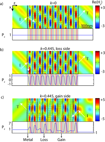
For k = 0 (Fig. 3a), the power is negatively refracted with an angle of . This result is in excellent agreement with our band structure calculations, which yield a refracted angle from Snell’s law of . The refractive index, = 1.36, at this non-Hermiticity value is independent of the illumination angle and direction. Indeed, for illumination in the plane, or an ‘endfire configuration’, the same refraction angle is observed (see Fig. 4a). The same refraction angle is also observed for illumination from all sides of the metamaterial (i.e., illumination from , , and )
Upon increasing the non-Hermiticity parameter of the metamaterial, the material becomes highly directional. Panels (b) and(c) of Fig. 3 illustrate the field profiles in a 10-layer -symmetric metamaterial when illumination is from the loss and gain side (i.e., illumination in the or directions, respectively). As a particular example, we consider k = 0.445. As seen, field profiles and refraction angles are completely different for illumination from + (loss side) versus (gain side). Illumination from + yields negative refraction at an angle of (see Fig. 3b). In contrast, illumination from yields negative refraction at an angle of (Fig. 3c).
More intriguingly, this structure is characterized by tunable reflection and transmission coefficients that can range from zero to at or above unity. This characteristic is illustrated in the lower panels of Fig. 3, which plot the normalized-to-incidence power at each position along the direction of propagation. For example, for illumination from the direction (panel (c)) power flows backward toward the source in the illumination region (), and away from the metamaterial on the transmission side (). Therefore, the metamaterial is completely transparent, in that the metamaterial can transmit all of the incident power, even though light is emitted back towards the source.
Moreover, for illumination from the direction (panel (b)) this metamaterial can achieve unidirectional invisibility. As seen, the power is unity on both sides of the metmaterial, indicating complete suppression of reflection on the illumination side and complete transmission on the other. Formally, perfect invisibility requires that the transmitted phase () equal the phase of a planewave propagating in free-space (). For the 10-layer metamaterial of Fig. 3b, = 2.75, so the object could be identified through the interference with a reference planewave. However, perfect unidirectional invisibility, i.e. where is an integer, can be achieved when the number of periods is increased to 55, 74 and 91.
The unusual directional scattering properties of the metamaterial can be rationalized by considering the power as light propagates through the array. For k = 0, power remains constant throughout the metamaterial (Fig.3a). However, with increasing k, power begins to oscillate within the metamaterial, with power increasing in the gain regions and decreasing in the loss regions. These plasmonic power oscillations are analogous to Bloch oscillations observed in both electronic and photonic crystals Sapienza et al. (2003) as well as PT-symmetric arrays Musslimani et al. (2008).
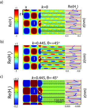
As a final visual example of the unusual unidirectional properties of this metamaterial, Fig. 4 plots the fields and refracted angles for illumination along the direction (endfire illumination). For a non-Hermiticity parameter k = 0, illumination at yields refraction at 30∘, respectively, in good agreement with the previously determined value of 31∘. With increasing non-Hermiticity parameter, however, illumination at yields markedly different results than illumination at . For example, for k = 0.445, illumination at yields a refracted angle of , while illumination at yields refraction along the metamaterial interface at an angle of . This double refraction does not just manifest itself in the intensity of the transmitted beam, but also in the profile of the fields, as seen in the right panels of Fig. 4.
We now consider the effect of varying the non-Hermiticity parameter on the scattering properties of the metamaterial. As before, we consider TM-polarized illumination with a 45∘ tilted planewave at = 445 nm. We limit our analysis to illumination along either (‘left-side illumination (L)’) or (‘right-side illumination (R)’) Based on Eq. 1, a generalized energy conservation formula can be derived as , where is the transmitted power and and are the reflected powers from the right and left sides, respectively Ge et al. (2012).
Figure 5 plots the reflection and transmission coefficients as a function of k. As seen in Fig. 5d, for k = 0.035, the transmitted power equals unity independent of the number of layers. Correspondingly at this point , shown in panel (b), vanishes for any number of layers. This property manifests itself as a peak in Fig. 4c, where the quotient of relative reflection coefficients is plotted. Importantly, for k = 0.035, this -symmetric metamaterial is still isotropic, characterized by circular equifrequency contours. Therefore, this PT-symmetric optical potential could enable lossless and far-field Vesalago lensing.
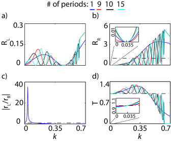
For larger non-Hermiticity parameters (0.035), exceeds unity. Interestingly, while the transmitted power varies with k and the number of unit cells, it never drops below 1 up through k = 0.445. At this non-Hermiticity value, the reflected power from the left/loss side () vanishes, as shown in Fig. 5a. For larger k, remains at or below unity. Non-Hermiticity parameters k above 0.63 yield purely imaginary , so no propagation is allowed through the metamaterial. This property is accompanied by a rapid drop in and strong increase in the reflectance for any number of layer.
While for left- (or loss)-side illumination the reflection coefficient is always less than unity, for right- (or gain)-side illumination the reflected power can exceed 1. This behavior is not monotonic however, depending strongly on the number of unit-cell layers and k. Indeed, only at k = 0 and k = 0.12 are the reflected powers from the left and right identical and equal to unity. For 0.12, the ratio remains below unity (Fig. 5c).
Table 2 summarizes some of the interesting scattering properties of the 10-unit-cell metamaterial extracted from Fig. 5. For k = 0, the metamaterial is Hermitian and lossless. With increasing -symmetric potentials, unusual features such as above unity transmission (k = 0.26), above unity reflection (k = 0.445) and uni-directional reflection suppression (k = 0.445 and k = 0.5) are observed. The normalized Bloch wavevector for each k is included in the last row of the table. Since is purely real, light propagates in a pass band of the metamaterial for all of these non-Hermiticity parameters.
| k = 0 | k = 0.035 | k = 0.26 | k = 0.445 | k = 0.5 | |
| 0.0080 | 0.03 | 0.0982 | 0 | 5 | |
| 0.0080 | 0 | 0.8397 | 2 | 0.1219 | |
| 0.9920 | 1 | 1.2872 | 1 | 0.9922 | |
| 0.7633 | 0.7609 | 0.6502 | 0.4683 | 0.3948 |
In conclusion, we have introduced the concept of a -symmetric metamaterial. The original lossless metamaterial, composed of a periodically-stacked 5-layer plasmonic waveguide, was designed to behave as an isotropic, three-dimensional negative refractive index material. By subjecting the plasmonic modes to -symmetric optical potentials, we demonstrated the broad tunability of the band curvatures, band gaps and effective refractive indices of the material. Small but non-zero non-Hermiticity parameters increased the transmission of the isotropic negative index metamaterial to unity. Larger non-Hermiticity parameters morphed the material from isotropic to anisotropic and directional. The highly unusual optical properties of -symmetric metamaterials could be used to devise an entirely new class of bulk synthetic media, ranging from lossless Veselago lenses to unidirectional metamaterial-based invisibility cloaks and new non-reciprocal nanophotonic devices.
Useful discussions and feedback from Dionne Group members are highly appreciated. This work is supported in part by a SLAC National Accelerator Laboratory LDRD award in concert with the Department of Energy, Office of Basic Energy Sciences, Division of Materials Sciences and Engineering, under contract DE-AC02-76SF00515. Funding from the Hellman Faculty Scholars program and a National Science Foundation CAREER Award (DMR-1151231) are also gratefully acknowledged.
References
- Valentine et al. (2008) J. Valentine, S. Zhang, T. Zentgraf, E. U. Avila, D. A. Genov, G. Bartal, and X. Zhang, Nature 455, 376 (2008).
- Yao et al. (2008) J. Yao, Z. Liu, Y. Liu, Y. Wang, C. Sun, G. Bartal, A. M. Stacy, and X. Zhang, Science 321, 930 (2008).
- Zhang et al. (2008) S. Zhang, D. A. Genov, Y. Wang, M. Liu, and X. Zhang, Phys. Rev. Lett. 101, 047401 (2008).
- Zhang et al. (2009) S. Zhang, Y. S. Park, J. Li, X. Lu, W. Zhang, , and X. Zhang, Phys. Rev. Lett. 102, 023901 (2009).
- Atre et al. (2013) A. C. Atre, A. G.-Etxarri, H. Alaeian, and J. A. Dionne, Adv. Optical Mater 1, 327 (2013).
- Xu et al. (2013) T. Xu, A. Agrawal, M. Abashin, K. J. Chau, and H. J. Lezec, Nature 497, 470 (2013).
- Shalaev (2007) V. M. Shalaev, Nat. Photonics 1, 41 (2007).
- Soukoulis and Wegener (2011) C. M. Soukoulis and M. Wegener, Nat. Photonics 5, 523 (2011).
- Lezec et al. (2007) H. J. Lezec, J. A. Dionne, and H. A. Atwater, Science 316, 430 (2007).
- Benisty et al. (2011) H. Benisty, A. Degiron, A. Lupu, A. D. Lustrac, S. Chénais, S. Forget, M. Besbes, G. Barbillon, A. Bruyant, S. Blaize, and G. Lérondel, Opt. Express 19, 18004 (2011).
- Guo et al. (2009) A. Guo, G. Salamo, D. Duchesne, R. Morandotti, M. Volatier-Ravat, V. Aimez, G. Siviloglou, and D. Christodoulides, Phys. Rev. Lett. 103, 093902 (2009).
- Ramezani et al. (2012) H. Ramezani, D. N. Christodoulides, V. Kovanis, I. Vitebskiy, and T. Kottos, Phys. Rev. Lett. 109, 033902 (2012).
- Makris et al. (2010) K. Makris, R. El-Ganainy, and D. Christodoulis, Phys. Rev. A 81, 063807 (2010).
- Zheng et al. (2010) M. C. Zheng, D. N. Christodoulides, R. Fleischmann, and T. Kottos, Phys. Rev. A 82, 010103 (2010).
- Longhi (2011) S. Longhi, J. Phys. A: Math Theor 44, 485302 (2011).
- Rüter et al. (2010) C. E. Rüter, K. G. Makris, R. El-Ganainy, D. N. Christodoulides, M. Segev, and D. Kip, Nat. Phys. 6, 192 (2010).
- Lin et al. (2011) Z. Lin, H. Ramezani, T. Eichelkraut, T. Kottos, H. Cao, and D. N. Christodoulides, Phys. Rev. Lett. 106, 213901 (2011).
- Mostafazadeh (2013) A. Mostafazadeh, Phys. Rev. A 87, 012103 (2013).
- Feng et al. (2013) L. Feng, Y. L. Xu, W. S. Fegadolli, M. H. Lu, J. E. Oliveira, V. R. Almeida, Y. F. Chen, and A. Scherer, Nat. Mater 12, 108 (2013).
- Makris et al. (2008) K. G. Makris, R. El-Ganainy, D. N. Christodoulides, and Z. H. Musslimani, Phys. Rev. Lett. 100, 103904 (2008).
- G.Castaldi et al. (2013) G.Castaldi, S. Savoia, V. Galdi, A. Alu, and N. Engheta, Phys. Rev. Lett. 110, 173901 (2013).
- Musslimani et al. (2008) Z. H. Musslimani, K. G. Makris, R. El-Ganainy, and D. N. Christodoulides, Phys. Rev. Lett. 100, 030402 (2008).
- Lazarides and Tsironis (2013) N. Lazarides and G. Tsironis, Phys. Rev. Lett. 110, 053901 (2013).
- Li et al. (2012) C. Li, C. Huang, H. Liu, and L. Dong, Opt. Lett. 37, 4543 (2012).
- He et al. (2011) Y. He, X. Zhu, D. Mihalache, J. Liu, and Z. Chen, Phys. Rev. A 85, 013831 (2011).
- Dmitriev et al. (2010) S. V. Dmitriev, A. A. Sukhorukov, and Y. S. Kivshar, Opt. Lett. 35, 2976 (2010).
- Chong et al. (2011) Y. D. Chong, L. Ge, and A. D. Stone, Phys. Rev. Lett. 106, 093902 (2011).
- Longhi (2010) S. Longhi, Phys. Rev. A 82, 031801 (2010).
- Bender et al. (1999) C. M. Bender, G. V. Dune, and P. N. Meisinger, Phys. Lett. A 252, 272 (1999).
- Bender (2007) C. M. Bender, Rep. Prog. Phys. 70, 947 (2007).
- Ahmed (2001) Z. Ahmed, Phys. Lett. A 282, 343 (2001).
- Bender and Boettcher (1998) C. M. Bender and S. Boettcher, Phys. Rev. Lett. 80, 5243 (1998).
- Mostafazadeh (2002) A. Mostafazadeh, J. Math. Phys. 43, 2814 (2002).
- Verhagen et al. (2010) E. Verhagen, R. de Waele, L. Kuipers, and A. Polman, Phys. Rev. Lett. 105, 223901 (2010).
- Note (1) Here we assume a lossless Drude model, but the results are generalizable to a realistic case including loss. See for example reference Benisty et al. (2011).
- Russell et al. (1995) P. S. J. Russell, T. A. Birks, and F. D. Lloyd-Lucas, Confined Electrons and Photons (1995).
- Ni et al. (2011) X. Ni, G. Naik, A. Kildishev, Y. Barnakov, A. Boltasseva, and V. Shalaev, Appl. Phys. B 103, 553 (2011).
- Jacob et al. (2012) Z. Jacob, I. I. Smolyaninov, and E. E. Narimanov, App. Phys. Lett. 100, 181105 (2012).
- Webb and Yang (2006) K. J. Webb and M. Yang, Opt. Lett. 31, 2130 (2006).
- Kim et al. (2012) J. Kim, V. Drachev, Z. Jacob, G. Naik, A. Boltasseva, E. Narimanov, and V. Shalaev, Opt. Express 20, 8100–8116 (2012).
- Zhao et al. (2011) W. Zhao, X. Huang, and Z. Lu, Opt. Express 19, 15297 (2011).
- Sapienza et al. (2003) R. Sapienza, P. Costantino, and D. Wiersma, Phys. Rev. Lett. 91, 263902 (2003).
- Ge et al. (2012) L. Ge, Y. Chong, and A. Stone, Phys. Rev. A 85, 023802 (2012).