Scalable photonic quantum computing assisted by quantum-dot spin in double-sided optical microcavity111Published in Opt. Express 21, 17671-17685 (2013)
Abstract
We investigate the possibility of achieving scalable photonic quantum computing by the giant optical circular birefringence induced by a quantum-dot spin in a double-sided optical microcavity as a result of cavity quantum electrodynamics. We construct a deterministic controlled-not gate on two photonic qubits by two single-photon input-output processes and the readout on an electron-medium spin confined in an optical resonant microcavity. This idea could be applied to multi-qubit gates on photonic qubits and we give the quantum circuit for a three-photon Toffoli gate. High fidelities and high efficiencies could be achieved when the side leakage to the cavity loss rate is low. It is worth pointing out that our devices work in both the strong and the weak coupling regimes.
pacs:
03.67.Lx, 42.50.Ex, 42.50.Pq, 78.67.HcI Introduction
Quantum information processing requires the precise control and manipulation of quantum states. It has been proven that single-qubit operations and two-qubit entangling gates are sufficient for universal quantum computing universal . One of the typical two-qubit gates is the controlled-not (CNOT) gate. The implementation of a photonic CNOT gate is one of the main directions as photons can be transmitted fast and reliably over a long distance in a less-loss optical fiber or a free space (low decoherence) and a single-qubit manipulation can be accomplished easily. Although they are perfect information carriers in quantum communication purpose, photons seem to be less suitable for quantum computing as they lack the sufficient strong interaction between each other. Surprisingly, Knill, Laflamme, and Milburn KLM demonstrated that using only single-photon sources, single-photon detectors, and linear optical elements, a CNOT gate on photonic qubits with a maximal success probability of 3/4 could be created with the use of polynomial resources. Subsequently, some improved works in theory theor1 ; theor2 ; theor3 ; theor4 and in experiment experi1 ; experi2 ; experi3 have been accomplished. Unfortunately, Pittman, Jacobs, and Franson theor1 showed that even with the help of maximally entangled two-photon pairs, the success probability of a CNOT gate can only be boosted to and it is still far lower than the maximum .
Toffoli gate is a fundamental quantum gate for three-qubit systems. It has been demonstrated that an arbitrary multi-qubit gate can be decomposed into a sequence of Toffoli and Hadamard gates Toffoli . Linear optical three-qubit Toffoli gate with an optimal success probability of 0.75% is proposed by Fiurášek Linear-optics . In 2009, Shende and Markov optimal proved that 6 CNOT gates are required for the synthesis of a Toffoli gate in the best case, which increases the difficulty to implement the Toffoli gate.
To avoid the probabilistic quantum computing with linear optics, a near deterministic CNOT gate based on weak cross-Kerr nonlinearities has been proposed kerr1 ; kerr2 and it provides a way for deterministic quantum computation in principle comput1 ; comput2 . Based on cross-Kerr nonlinearity, Lin and He proposed a scheme for a three-qubit Toffoli gate Toffoli-Kerr , and the scheme contains 4 two-qubit gates and 2 additional photonic qubits are required. A giant Kerr nonlinearity is still a challenge with current technology, even with electromagnetically induced transparency EIT1 , as the initially achieved phase shift at the single-photon level is only in the order of EIT2 . Moreover, it is currently not clear whether these nonlinearities are sufficient for the natural implementation of single-photon qubit gates.
Previous works showed that the spin of a singly charged electron confined in a quantum dot (QD) QD1 ; QD2 ; QD3 ; QD4 ; QD5 ; QD6 can be used for storing and processing quantum information, due to the long electron-spin coherence time () cohertime1 ; cohertime2 ; cohertime3 ; cohertime4 ; cohertime5 ; cohertime6 using spin-echo techniques. The QD spin state can be initiated by means of optical pumping or optical cooling eigen1 ; eigen2 , and then by performing single-spin rotations cohertime1 ; cohertime2 or via a spin-flip Raman transition eigen1 , the spin superposition state can be obtained. Ultrafast optical coherent control on QD spins has been demonstrated manipulating1 ; manipulating2 ; manipulating3 . The system based on QD has received increasing attention because of the comparative easiness of incorporating a QD into a solid-state cavity, which could facilitate the deterministic transfer of quantum information between the photonic qubit and the spin qubit, and this transformation extends the potential applications of quantum information and quantum communication. A spin-QD-cavity unit, e.g., an excess electron confined in a self-assembled In(Ga)As QD or a GaAs interface QD inside an optical resonant microcavity was proposed by Hu et al. Hu1 ; Hu2 . This unit is the key element for constructing universal hybrid quantum gates, entangled state analyzer, teleportation, deterministic photonic hyper-CNOT gates, quantum repeaters, entanglement purification, and creating entangled states and hyperentangled Bell states Hu1 ; Hu2 ; Hu3 ; Hu4 ; Appli1 ; weinot ; aa0 ; aa1 ; aa2 ; aa3 ; aa4 ; aa5 . In this unit, the QD spin represents the qubit and promises a scalable quantum computing, and the QD spin manipulation is well developed using the pulsed magnetic-resonance technique.
In this article, we investigate the possibility of achieving scalable photonic quantum computing, assisted by a QD spin in a double-sided optical microcavity. By the giant optical circular birefringence for the right-circularly and the left-circularly lights induced by a QD spin in a microcavity as a result of cavity quantum electrodynamics (QED), we construct a CNOT gate and a Toffoli gate for photonic qubits. Both these two quantum gates are based on some single-photon input-output processes and the readout on an electron-medium spin. They work in a deterministic way. The CNOT and the Toffoli gates discussed in weinot ; Appli1 are encoded on a control photon polarization qubit (or an electron-spin qubit) and target electron spin qubits (photon polarization qubits). Both the present quantum gates are encoded on the polarization of single photonic qubits, and they have several advantages, including scalable, low decoherence, deterministic, and suitable for information transmission. The electron confined in the cavity only plays a role of the medium. We analyze the experimental feasibility of these two quantum gates, concluding that our proposals can be implemented with current technology.
II Deterministic photonic two-qubit CNOT gate without additional photonic qubits
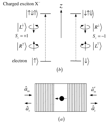
Let us consider a singly charged electron self-assembled GaAs/InAs QD or GaAs interface QD confined in an optical resonant microcavity with two partially reflective mirrors Hu2 ; Appli1 (called it a spin-QD-double-side-cavity unit below, see Fig. 1(a)). When an excess electron is injected into the QD, optical excitation can create a trion (also called negatively charged exciton) which consists of two electrons and a hole exciton1 . The optical properties of the unit are determined by , and there are only two dipole transitions which lead to large differences in the phase or the amplitude of the reflection and the transmission coefficients between two circular polarizations of photons, one involving a photon and the other involving a photon (see Fig. 1(b)) exciton2 due to Pauli’s exclusion principle. In the following, we consider the case that a dipole is resonant with the cavity mode and is probed with a resonant light. If the injected photon couples to the dipole, that is, the photon can be absorbed to create a , the cavity is reflective, and both the polarization and the propagation direction of the photon will be flipped. Otherwise, the cavity is transmissive and the photon will acquire a mod phase shift relative to the reflected photon. The interaction between the input photons with and the electron spin in the cavity is described as follows Hu2 ; Appli1 ; weinot :
| (1) |
Here and represent the spin states and of the excess electron, respectively. and represent the spin states and of the heavy-hole, respectively. The spin quantization axis for angular momentum is along the normal direction of the cavity, that is, the axis. The right-circularly-polarized photon and the left-circularly-polarized photon marked by and , respectively, and the subscript () indicates their propagation direction along (against) the axis. Such a unit can act as an entanglement beam splitter (EBS) which can splits directly an initial product state of a photon-spin system into two entangled states via the transmission and reflection in a deterministic way. It is worth pointing out that a polarization-degenerate cavity mode is required to transfer the polarization of the photon to the spin of an atom-like system, or vice the versa in several quantum information applications, and it is also necessary in our schemes. Excellent progress has been made on the unpolarized micropillar cavities unpolarized-pillar1 ; unpolarized-pillar2 ; unpolarized-pillar3 and the H1 photonic crystal cavities unpolarized-photon1 ; unpolarized-photon2 .
In a single electron charged QD system, the spontaneous spin flip Raman scattering transitions, and , are ideally dark dark , nevertheless, in a realistic QD system, there is due to the inherent hole mixing or the factor that a in-plane magnetic field is not parallel to the axis. Here, is the allowed transition and is the forbidden transition eigen1 . The strong hyperfine interaction between the excess electron and the QD nuclear spin ensemble leads to a spin flip () at the rate . is strongly suppressed even under a weak magnetic field suppress1 ; suppress2 . When , the optical transitions do not alter the spin state occupancieseigen1 . The energy splitting, which results in a net spin flip, does not occur for charged excitons due to the quenched exchange interaction occur1 ; occur2 , and our schemes are immune to energy splitting in principle.
In the following, we will utilize this EBS to construct a photonic two-qubit CNOT gate.
Figure 2 shows the principle of the present deterministic scheme for implementing a photonic two-qubit CNOT gate which requires no auxiliary photonic qubits. Now, let us describe the quantum circuit in detail. Suppose the control photon , the target photon , and the excess electron-medium in the cavity are prepared in the states
| (2) |
respectively. Here .
First, the control photon is sent into the input port c and it reaches PBS1. PBS1 transmits the right-circularly-polarized photon and reflects the left-circularly-polarized photon, which results in the fact that the control photon in the state is injected into the cavity and the control photon in the state deserts the cavity. That is, PBS1 transforms the initial state of the whole system into . Here
| (3) | |||||
| (4) |
The subscript () of () denotes the photon is in the state emitting from spatial mode . Before and after the control photon coming from spatial mode 2 interacts with the QD inside the cavity, a Hadamard operation (, i.e., passing through HWP1 whose optical axes is set to be ) is performed on it and a Hadamard operation (, e.g., using a microwave pulse or an optical pulse manipulating1 ; manipulating2 ; manipulating3 ) is also performed on the electron, simultaneously. These two Hadamard operations complete the transformations as following:
| (5) |
| (6) |
After the photon emitting from spatial mode 2 interacts with the QD inside the cavity, one can obtain
| (7) |
PBS2 transforms and into and , respectively, and then an (i.e., passing through HWP2) and an are performed on the control photon and the electron, respectively. After the wave-packets emitting from spatial modes 1 and 5 arrive PBS3 simultaneously, one can obtain
| (8) |
Next, the target photon is injected into the cavity through the input port t. PBS4 completes the transformations and . After the target photon interacts with the QD, it is emitted from path 9. This nonlinear interaction transforms the state of the whole system into
| (9) |
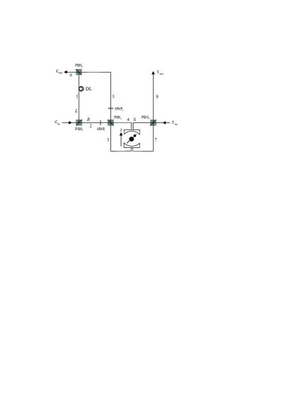
At last, one performs an on the excess electron and measures it in the basis . According to the outcome of this measurement, a proper feed-forward operation is performed on the control qubit to complete the CNOT gate. If the spin is in the state , is performed on the photon emitting from the output port c. Otherwise, nothing is performed on the photons from both c and t. With these measurement and operation, the state of the two-photon system becomes
| (10) |
One can see that the state of the target photonic qubit is flipped when the control photonic qubit is in the state , while it does not change when the control photon is in the state , compared to the original state of the two-photon system . That is, the quantum circuit shown in Fig. 2 can be used to achieve a deterministic CNOT gate on two photonic qubits with a success probability of 100% in principle.
III Deterministic Toffoli gate for three photonic qubits
The schematic diagram for implementing a deterministic three-qubit Toffoli gate, which performs a NOT operation on the target qubit if and only if (iff) both the two control qubits are in the polarization state , is shown in Fig. 3. Suppose the inputting control photons and , and the target photon are prepared in arbitrary polarization superposition states as follows:
| (11) |
Here . To show the principle of the present Toffoli gate explicitly, we give the evolution of the whole system composed of two control photons and , a target photon , and an excess electron-medium below. Its initial state is
| (12) |
Here is the initial state of the excess electron-medium confined in the QD inside the cavity.
First, the first control photon is injected into the input port c (depicted in Fig. 3(a)). PBS1 splits the control photon into two wave-packets, that is, and . The photon in the state is injected into the cavity, while the photon in the state does not interact with the QD inside the cavity. With the same arguments as made for the CNOT gate above, we find that after the first control photon interacts with the QD inside the cavity, it is emitted from the output port c with the state of the whole system as
| (13) |
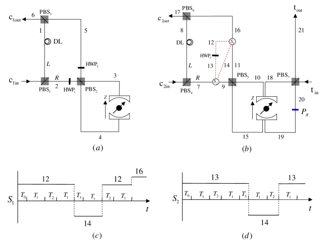
Second, the second control photon is injected into the input port (depicted in Fig. 3(b)), and then and . The photon in the state is injected into the cavity and interacts with the QD inside the cavity, while the photon in the state does not pass through the cavity. The interaction between the QD and the second control photon coming from path 7 transforms the state of the whole system into
| (14) |
Next, we lead the photon in the state or to spatial mode 12 with the optical switch S1, that is, and . Before the photon reaches the optical switch S2, Hadamard operations (i.e., passing through HWP3) and are performed on the photon and the electron, respectively. The interaction between the second control photon coming from path 13 and the QD transforms the state of the system into
| (15) |
Subsequently, an is performed on the electron, which transforms the state of the system into
| (16) |
Next, we lead the photon in the state or to spatial path 14 for interacting with the QD inside the cavity again by using the switch S1. The evolution of the lead-back photon can be described by the processes and , respectively.
Third, as depicted in Fig. 3(b), the target photon is injected into the input port and interacts with the QD inside the cavity after an is performed on the electron described by Eq. (16) and before the photon emitting from path 11 interacts with the QD. The evolution of the target photon can be described by the processes , , , and , respectively.
Fourth, we perform an on the electron after the target photon interacts with the QD and before the second control photon in the state or interacts with the QD. After and interact with the QD, the state of the whole system becomes
| (17) |
Next, we lead the photon emitting from path 11 to path 12 by using the switch S1 (, ) for passing through HWP3 (i.e., an is performed on and ). Also, an is performed on the electron. When the photon is emitted from spatial mode 13, it is led to the cavity by S2. After the photon interacts with the QD inside the cavity, it is emitted from path 16 with the state of the whole system as
| (18) |
When the photons in the states and pass through PBS6 simultaneously, the state of the whole system becomes
| (19) |
Fifth, an is first performed on the electron and then a measurement in the basis is taken on it. In order to complete the Toffoli gate with a success probability of 100%, and are performed on the outing control photon and the outing target photon , respectively iff the spin is in . is performed on the outing target photon iff the spin is in . After these operations, the finial state of the three-photon system becomes
| (20) |
One can see that the state of the target photonic qubit is flipped when both the two control photonic qubits and are in the state , compared to the initial state of the photon system composed of the three photonic qubits. That is, the quantum circuit shown in Fig. 3 can be used to construct a Toffoli gate on a three-photon system in a deterministic way.
IV Discussion and summary
Let us discuss the feasibility to implement our proposals in a promising system with a GaAs- or InAs-based QD confined in an optical resonant microcavity with two partially reflective mirrors.
We can briefly review the reflection and the transmission coefficients of the cavities, for describing the photon-spin interaction in the system. It is known that they can be obtained by solving the Heisenberg equations of motion for the cavity field operator and the QD dipole operator
| (21) |
combining with the input-output relations for the cavity Heisenberg
| (22) |
and taking . Hu et al. Hu2 presented an explicit expression for the transmission coefficient and the reflection coefficient . They can be expressed as
| (23) |
Here , , and denote the frequencies of the external field (probe photon), the cavity mode, and the transition, respectively. denotes the cavity coupling rate. , , and denote the decay rates of the dipole, the cavity field, and the leaky modes (side leakage), respectively. As shown in Fig. 1(a), and are the noise operators related to the reservoirs needed to conserve the commutation. () and and () are the input field operators and the output field operators, respectively.
The reflected and the transmitting lights feel phase shifts due to the complex reflection and transmission coefficients given by Eq. (23), and the phase shift can be adjusted by (). In our work, we set the cavity to be resonant with the and the input photons, that is, , and the reflection and the transmission coefficients of the coupled (hot, that is, ) cavity described by Eq. (23) can be simplified as
| (24) |
By taking =0, the reflection and the transmission coefficients of the uncoupled cavity (cold cavity) can be written as
| (25) |
Therefore, in a realistic spin-QD-double-side-cavity unit, the change of the input photon states in the system can be described as Appli1
| (26) |
First, we consider an ideal case in which the side leakage is much lower than the output coupling rate (that is, is negligible). Hu et al. Hu2 pointed out that under this condition, , , , and can be achieved in the strong coupling regime . In this time, Eq. (26) becomes Eq. (1), and the fidelities and the efficiencies of our gates can achieve unity. Unfortunately, this is a big challenge for QD-micropillar cavities although a significant progress has been made challenge ; observed1 . If the cavity side leakage which will cause bit-flip errors is taken into account, the fidelities of our CNOT and Toffoli gates can be calculated as
| (27) |
where
| (28) |
Here . represents the finial state in a realistic QD-cavity system in our protocols, whereas represents the final state in the ideal condition.
In our work, the efficiency of the gate is defined as the ratio of the the number of the outputting photons to the inputting photons. The efficiencies of the CNOT and Toffoli gates can be expressed as
| (29) |
Here .
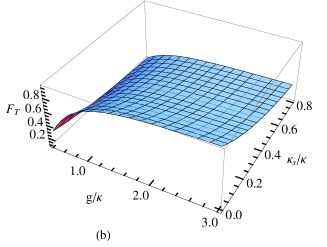
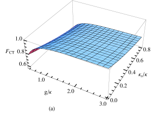
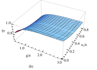
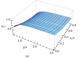
For QD-cavity systems, strong coupling has been demonstrated. Forchel group challenge observed for a diameter micropillar with the quality factor In(Ga)As QD-microcavity. for , , and In(Ga)As QD-microcavity is also observed by this group challenge ; observed1 . Yoshie observed2 reported for QD-nanocavity. Hu et al. Hu4 reported for In(Ga)As QD-microcavity in 2011. In 2011, Young et al. ABYoung confirmed in pillar microcavity. Fig. 4 and Fig. 5 present the fidelities and the efficiencies of our gates vary with and . They indicate that the fidelities and the efficiencies decrease with , and increase with . Let us now present some data in detail. When and , , with and . If and , , with and . From Fig. 4 and Fig. 5, we find that by taking a low , a near-unity fidelity and efficiency can be achieved in the strong-coupling regime. Moreover, a high fidelity and a high efficiency are achieved possibly in the weak-coupling regime.
Hu et al. Hu2 ; Hu4 showed that besides the side leakage of the cavity, the electron-spin decoherence, the exciton dephasing, and the imperfect optical selection rule reduce the fidelity of a gate by few percents, respectively. The electron-spin decoherence decreases the fidelities of the gates by a factor
| (30) |
Here and are the electron spin coherence time and the time interval between two input photons encoded for the gates, respectively. The electron-spin decoherence can reduce the fidelities by few presents as could be maintained for more than s using spin-echo techniques cohertime1 ; cohertime2 and , which limited by the critical photon and the cavity photon life time and should be shorter than for getting a high fidelity, can be longer than ns interval . The exciton dephasing caused by the exciton decoherence in a QD reduces the fidelities by a factor
| (31) |
and are the cavity photon lifetime and the exciton coherence time, respectively. The trion phasing induces the state of the electron with equal polarized superposition to be
| (34) |
as the information of the photonic qubits is transformed into the electron through the excitonic state. It has been reported that the exciton slightly decreases the fidelities because the exciton dephasing includes the optical dephasing and the spin dephasing. In self-assembled In(Ga) QD, the optical coherence time of exciton can be maintained several hundreds of picoseconds opticldeph1 ; opticldeph2 ; opticldeph3 and it is ten times longer than the cavity photon lifetime ( tens of picoseconds). The trion coherence time of the exciton ( ns has been reported) is at least three orders of longer than the cavity photon lifetime spindeph1 ; spindeph2 ; spindeph3 . The imperfect optical selection rule caused by the heavy-light hole mixing opticselec in a realistic QD could be reduced by engineering the shape and the size of QDs or by choosing different types of QDs.
The time interval between the inputting photons . Here critical is the number of the critical photons and is the cavity photon lifetime. and ns can be achieved interval for a micropillar microcavity with m and 104. Therefore, the time difference between the inputting photons can be longer than =4.5 ns interval and it is several orders shorter than the single electron charged QD spin coherence time s cohertime1 ; cohertime2 ; cohertime3 ; cohertime4 ; cohertime5 ; cohertime6 . As the CNOT and Toffoli gates are encoded on two and three photons, respectively, the speed of the photon-qubit for those two gates interacting with the spin should be less than and , respectively.
Schemes for realizing the quantum gate on photonic qubits by means of the light-matter interactions have been received much attention. An auxiliary photonic qubit or qudit, as employed in kerr1 ; kerr2 ; Toffoli-Kerr ; Ionicioiu , is unnecessary in our schemes. Our scheme as shown in Fig. 2, 2 two-qubit entangling gates acting on light-matter systems are required, less than the ones in Yang ; Duan which require 3 hybrid gates. Refs. Hu2 ; Devitt ; Feng discussed the photonic entanglement assisted by an atom or a QD. However, based on parity-check gates, an additional photonic qubit is necessary to construct a two-qubit quantum gate. Procedure for multi-qubit gates using parity-check gates is an open question. The circuits of the photonic qubit gates assisted by matter-medium are mostly focused on two-qubit cases kerr1 ; Yang ; Duan ; Wong , while the ones for multi-qubit systems are much more complex. Moreover, it is usual not an appealing method to realize a multi-qubit gates by means of two-qubit gates. For example, the synthesis of a Toffoli gate requires 5 two-qubit entangling gates assisted by a qudit Ionicioiu , or requires 6 CNOT gates and some single-qubit gates optimal . In our work, we not only investigated the realization of a photonic two-qubit CNOT gate, but also generalized it to the three-qubit case. Moreover, our schemes are based on a QD-cavity system. It is easier to trap a QD inside the cavity than that for an atom, and the speed of the optical coherent manipulation of a QD is far faster than an atom. Compared with the gates based on spin-QD-single-side-cavity systems, the ones based on spin-QD-doubled-side-cavity systems are more robust and flexible Hu2 .
In summary, we have investigated the possibility of achieving scalable photonic quantum computing by the giant optical circular birefringence induced by a singly charged QD spin in a double-sided optical microcavity as a result of cavity QED and have proposed an attractive scheme for a deterministic CNOT gate on two photonic qubits by two single-photon input-output processes and the readout on an electron-medium spin. It requires no additional photonic qubits, different from those based on cross-Kerr nonlinearity or parity-check gates. Moreover, we have presented a deterministic scheme for implementing a three-qubit Toffoli gate on photon systems. In our schemes, the spin-QD-double-side-cavity system is only a solid medium. When the ratio of the side leakage to the cavity loss is low, a near-unity fidelity can be achieved in the strong-coupling regime and a high fidelity can be achieved in the weak-coupling regime. With these two quantum gates on photonic qubits and single-photon unitary operations, universal quantum computing can be achieved on photon systems in principle.
ACKNOWLEDGEMENTS
This work is supported by the National Natural Science Foundation of China under Grant No. 11174039, NECT-11-0031, and the Fundamental Research Funds for the Central Universities.
References
- (1) A. Barenco, C. H. Bennett, R. Cleve, D. P. DiVincenzo, N. Margolus, P. Shor, T. Sleator, J. A. Smolin, and H. Weinfurter, “Elementary gates for quantum computation,” Phys. Rev. A 52, 3457-3457 (1995).
- (2) E. Knill, R. Laflamme, and G. J. Milburn, “A scheme for efficient quantum computation with linear optics,” Nature (London) 409, 46-52 (2001).
- (3) T. B. Pittman, B. C. Jacobs, and J. D. Franson, “Probabilistic quantum logic operations using polarizing beam splitters,” Phys. Rev. A 64, 062311 (2001).
- (4) E. Knill, “Quantum gates using linear optics and postselection,” Phys. Rev. A 66, 052306 (2002).
- (5) M. A. Nielsen, “Optical quantum computation using cluster states,” Phys. Rev. Lett. 93, 040503 (2004).
- (6) D. E. Browne and T. Rudolph, “Resource-efficient linear optical quantum computation,” Phys. Rev. Lett. 95, 010501 (2005).
- (7) T. B. Pittman, M. J. Fitch, B. C. Jacobs, and J. D. Franson, “Experimental controlled-not logic gate for single photons in the coincidence basis,” Phys. Rev. A 68, 032316 (2003).
- (8) J. L. O’Brien, G. J. Pryde, A. G. White, T. C. Ralph, and D. Branning, “Demonstration of an all-optical quantum controlled-not gate,” Nature (London) 426, 264-267 (2003).
- (9) S. Gasparoni, J. W. Pan, P. Walther, T. Rudolph, and A. Zeilinger, “Realization of a photonic controlled-not gate sufficient for quantum computation,” Phys. Rev. Lett. 93, 020504 (2004).
- (10) Y. Y. Shi, “Both Toffoli and controlled-not need little help to do universal quantum computation,” Quantum Inf. Comput. 3, 084-092 (2003).
- (11) J. Fiurášek, “Linear-optics quantum Toffoli and Fredkin gates,” Phys. Rev. A 73, 062313 (2006).
- (12) V. V. Shende and I. L. Markov, “On the CNOT-cost of Toffoli gate,” Quantum Inf. Comput. 9, 0461-0486 (2009).
- (13) K. Nemoto and W. J. Munro, “Nearly deterministic linear optical controlled-not gate,” Phys. Rev. Lett. 93, 250502 (2004).
- (14) Q. Lin and J. Li, “Quantum control gates with weak cross-Kerr nonlinearity,” Phys. Rev. A 79, 022301 (2009).
- (15) W. J. Munro, K. Nemoto, and T. P. Spiller, “Weak nonlinearities: A new route to optical quantum computation,” New J. Phys. 7, 137 (2005).
- (16) T. P. Spiller, K. Nemoto, S. L. Braunstein, W. J. Munro, P. van Loock , and G. J. Milburn, “Quantum computation by communication,” New J. Phys. 8, 30 (2006).
- (17) Q. Lin and B. He, “Single-photon logic gates using minimal resources,” Phys. Rev. A 80, 042310 (2009).
- (18) M. Fleischhauer, A. Imamoglu, and J. P. Marangos, “Electromagnetically induced transparency: Optics in coherent media,” Rev. Mod. Phys. 77, 633-673 (2005).
- (19) H. Schmidt and A. Imamogdlu, “Giant Kerr nonlinearities obtained by electromagnetically induced transparency,” Opt. Lett. 21, 1936-1938 (1996).
- (20) D. Loss and D. P. DiVincenzo, “Quantum computation with quantum dots,” Phys. Rev. A 57, 120-126 (1998).
- (21) A. Imamoglu, D. D. Awschalom, G. Burkard, D. P. DiVincenzo, D. Loss, M. Sherwin, and A. Small, “Quantum information processing using quantum dot spins and cavity QED,” Phys. Rev. Lett. 83, 4204-4207 (1999).
- (22) C. Piermarocchi, P. C. Chen, L. J. Sham, and D. G. Steel, “Optical RKKY interaction between charged semiconductor quantum dots,” Phys. Rev. Lett. 89, 167402 (2002).
- (23) T. Calarco, A. Datta, P. Fedichev, E. Pazy, and P. Zoller, “Spin-based all-optical quantum computation with quantum dots: Understanding and suppressing decoherence,” Phys. Rev. A 68, 012310 (2003).
- (24) S. M. Clark, K. M. C. Fu, T. D. Ladd, and Y. Yamamoto, “Quantum computers based on electron spins controlled by ultrafast off-resonant single optical pulses,” Phys. Rev. Lett. 99, 040501 (2007).
- (25) Z. R. Lin, G. P. Guo, T. Tu, F. Y. Zhu, and G. C. Guo, “Generation of quantum-dot cluster states with a superconducting transmission line resonator,” Phys. Rev. Lett. 101, 230501 (2008).
- (26) J. R. Petta, A. C. Johnson, J. M. Taylor, E. A. Laird, A. Yacoby, M. D. Lukin, C. M. Marcus, M. P. Hanson, and A. C. Gossard, “Coherent manipulation of coupled electron spins in semiconductor quantum dots,” Science 309, 2180-2184 (2005).
- (27) A. Greilich, D. R. Yakovlev, A. Shabaev, A. L. Efros, I. A. Yugova, R. Oulton, V. Stavarache, D. Reuter, A. Wieck, and M. Bayer, “Mode locking of electron spin coherences in singly charged quantum dots,” Science 313, 341-345 (2006).
- (28) A. Greilich, A. Shabaev, D. R. Yakovlev, A. L. Efros, I. A. Yugova, D. Reuter, A. D. Wieck, and M. Bayer, “Nuclei-induced frequency focusing of electron spin coherence,” Science 317, 1896-1899 (2007).
- (29) X. D. Xu, W. Yao, B. Sun, D. G. Steel, A. S. Bracker, D. Gammon, and L. J. Sham, “Optically controlled locking of the nuclear field via coherent dark-state spectroscopy,” Nature (London) 459, 1105-1109 (2009).
- (30) D. Brunner, B. D. Gerardot, P. A. Dalgarno, G. Wüst, K. Karrai, N. G. Stoltz, P. M. Petroff, and R. J. Warburton, “A coherent single-hole spin in a semiconductor,” Science 325, 70-72 (2009).
- (31) D. Press, K. De Greve, P. L. McMahon, T. D. Ladd, B. Friess, C. Schneider, M. Kamp, S. Höfling, A. Forchel, and Y. Yamamoto, “Ultrafast optical spin echo in a single quantum dot,” Nature Photon. 4, 367-370 (2010).
- (32) M. Atat re, J. Dreiser, A. Badolato, A. Hogele, K. Karrai, and A. Imamoglu, “Quantum-dot spin-state preparation with near-unity fidelity,” Science 312, 551-553 (2006).
- (33) X. D. Xu, Y. W. Wu, B. Sun, Q. Huang, J. Cheng, D. G. Steel, A. S. Bracker, D. Gammon, C. Emary, and L. J. Sham, “Fast spin state initialization in a singly charged InAs-GaAs quantum dot by optical cooling,” Phys. Rev. Lett. 99, 097401 (2007).
- (34) J. Berezovsky, M. H. Mikkelsen, N. G. Stoltz, L. A. Coldren, and D. D. Awschalom, “Picosecond coherent optical manipulation of a single electron spin in a quantum dot,” Science 320, 349-352 (2008).
- (35) D. Press, T. D. Ladd, B. Y. Zhang, and Y. Yamamoto, “Complete quantum control of a single quantum dot spin using ultrafast optical pulses,” Nature (London) 456, 218-221 (2008).
- (36) A. Greilich, S. E. Economou, S. Spatzek, D. R. Yakovlev, D. Reuter, A. D. Wieck, T. L. Reinecke and M. Bayer, “Ultrafast optical rotations of electron spins in quantum dots,” Nature Phys. 5, 262-266 (2009).
- (37) C. Y. Hu, A. Young, J. L. O’Brien, W. J. Munro, and J. G. Rarity, “Giant optical Faraday rotation induced by a single-electron spin in a quantum dot: Applications to entangling remote spins via a single photon,” Phys. Rev. B 78, 085307 (2008).
- (38) C. Y. Hu, W. J. Munro, J. L. O’Brien, and J. G. Rarity, “Proposed entanglement beam splitter using a quantum-dot spin in a double-sided optical microcavity,” Phys. Rev. B 80, 205326 (2009).
- (39) C. Y. Hu, W. J. Munro, and J. G. Rarity, “Deterministic photon entangler using a charged quantum dot inside a microcavity,” Phys. Rev. B 78, 125318 (2008).
- (40) C. Y. Hu and J. G. Rarity, “Loss-resistant state teleportation and entanglement swapping using a quantum-dot spin in an optical microcavity,” Phys. Rev. B 83, 115303 (2011).
- (41) C. Bonato, F. Haupt, S. S. R. Oemrawsingh, J. Gudat, D. Ding, M. P. van Exter, and D. Bouwmeester, “CNOT and Bell-state analysis in the weak-coupling cavity QED regime,” Phys. Rev. Lett. 104, 160503 (2010).
- (42) H. R. Wei and F. G. Deng, “Universal quantum gates for hybrid systems assisted by quantum dots inside double-sided optical microcavities,” Phys. Rev. A 87, 022305 (2013).
- (43) B. C. Ren, H. R. Wei, and F. G. Deng, “Deterministic photonic spatial-polarization hyper-controlled-not gate assisted by quantum dot inside one-side optical microcavity,” Laser Phys. Lett. (accepted); arXiv:1303.0056.
- (44) T. J. Wang, S. Y. Song, and G. L. Long, “Quantum repeater based on spatial entanglement of photons and quantum-dot spins in optical microcavities,” Phys. Rev. A 85, 062311 (2012).
- (45) C. Wang, Y. Zhang, and R. Zhang, “Entanglement purification based on hybrid entangled state using quantum-dot and microcavity coupled system,” Opt. Express 19, 25685-25695 (2011).
- (46) C. Wang, Y. Zhang, and G. S. Jin, “Entanglement purification and concentration of electron-spin entangled states using quantum-dot spins in optical microcavities,” Phys. Rev. A 84, 032307 (2011).
- (47) B. C. Ren, H. R. Wei, M. Hua, T. Li, and F. G. Deng, “Complete hyperentangled-Bell-state analysis for photon systems assisted by quantum-dot spins in optical microcavities,” Opt. Express 20, 24664-24677 (2012).
- (48) T. J. Wang, Y. Lu, and G. L. Long, “Generation and complete analysis of the hyperentangled Bell state for photons assisted by quantum-dot spins in optical microcavities,” Phys. Rev. A 86, 042337 (2012).
- (49) R. J. Warburton, C. S. Dürr, K. Karrai, J. P. Kotthaus, G. M. Ribeiro, and P. M. Petroff, “Charged excitons in self-assembled semiconductor quantum dots,” Phys. Rev. Lett. 79, 5282-5285 (1997).
- (50) C. Y. Hu, W. Ossau, D. R. Yakovlev, G. Landwehr, T. Wojtowicz, G. Karczewski, and J. Kossut, “Optically detected magnetic resonance of excess electrons in type-I quantum wells with a low-density electron gas,” Phys. Rev. B 58, R1766-R1769 (1998).
- (51) C. Bonato, D. Ding, J. Gudat, S. Thon, H. Kim, P. M. Petroff, M. P. van Exter, and D. Bouwmeester, “Tuning micropillar cavity birefringence by laser induced surface defects,” Appl. Phys. Lett. 95, 251104 (2009).
- (52) J. Gudat, C. Bonato, E. van Nieuwenburg, S. Thon, H. Kim, P. M. Petroff, M. P. van Exter, and D. Bouwmeester, “Permanent tuning of quantum dot transitions to degenerate microcavity resonances,” Appl. Phys. Lett. 98, 121111 (2011).
- (53) C. Bonato, E. van Nieuwenburg, J. Gudat, S. Thon, H. Kim, M. P. van Exter, and D. Bouwmeester, “Strain tuning of quantum dot optical transitions via laser-induced surface defects,” Phys. Rev. B 84, 075306 (2011).
- (54) I. J. Luxmoore, E. D. Ahmadi, B. J. Luxmoore, N. A. Wasley, A. I. Tartakovskii, M. Hugues, M. S. Skolnick, and A. M. Fox, “Restoring mode degeneracy in H1 photonic crystal cavities by uniaxial strain tuning,” Appl. Phys. Lett. 100, 121116 (2012).
- (55) J. Hagemeier, C. Bonato, T. A. Truong, H. Kim, G. J. Beirne, M. Bakker, M. P. van Exter, Y. Q. Luo, P. Petroff, and D. Bouwmeester, “H1 photonic crystal cavities for hybrid quantum information protocols,” Opt. Express 20, 24714 (2012).
- (56) M. V. G. Dutt, J. Cheng, B. Li, X. D. Xu, X. Q. Li, P. R. Berman, D. G. Steel, A. S. Bracker, D. Gammon, S. E. Economou, R. B. Liu, and L. J. Sham, “Stimulated and spontaneous optical generation of electron spin coherence in charged GaAs quantum dots,” Phys. Rev. Lett. 94, 227403 (2005).
- (57) J. M. Elzerman, R. Hanson, L. H. W. van Beveren, B. Witkamp, L. M. K. Vandersypen, and L. P. Kouwenhoven, “Single-shot read-out of an individual electron spin in a quantum dot,” Nature (London) 430, 431-425 (2004).
- (58) M. Kroutvar, Y. Ducommun, D. Heiss, M. Bichler, D. Schuh, G. Abstreiter, and J. J. Finley, “Optically programmable electron spin memory using semiconductor quantum dots,” Nature (London) 432, 81-84 (2004).
- (59) M. Bayer, G. Ortner, O. Stern, A. Kuther, A. A. Gorbunov, and A. Forchel, “Fine structure of neutral and charged excitons in self-assembled In(Ga)/As(Al)GaAs quantum dots,” Phys. Rev. B 65, 195315 (2002).
- (60) J. J. Finley, D. J. Mowbray, M. S. Skolnick, A. D. Ashmore, C. Baker, and A. F. G. Monte, “Fine structure of charged and neutral excitons in InAs-Al0.6 Ga0.4As quantum dots,” Phys. Rev. B 66, 153316 (2002).
- (61) D. F. Walls and G. J. Milburn, Quantum Optics (Springer-Verlag, Berlin, 1994).
- (62) S. Reitzenstein, C. Hofmann, A. Gorbunov, M. Strauß, S. H. Kwon, C. Schneider, A. Löffler, S. Höfling, M. Kamp, and A. Forchel, “AlAs/GaAs micropillar cavities with quality factors exceeding 150.000,” Appl. Phys. Lett. 90, 251109 (2007).
- (63) J. P. Reithmaier, G. Sek, A. Löffler, C. Hofmann, S. Kuhn, S. Reitzenstein, L. V. Keldysh, V. D. Kulakovskii, T. L. Reinecke, and A. Forchel, “Strong coupling in a single quantum dot-semiconductor microcavity system,” Nature (London) 432, 197-200 (2004).
- (64) T. Yoshie, A. Scherer, J. Hendrickson, G. Khitrova, H. M. Gibbs, G. Rupper, C. Ell, O. B. Shchekin, and D. G. Deppe, “Vacuum Rabi splitting with a single quantum dot in a photonic crystal nanocavity,” Nature (London) 432, 200-203 (2004).
- (65) A. B. Young, R. Oulton, C. Y. Hu, A. C. T. Thijssen, C. Schneider, S. Reitzenstein, M. Kamp, S. Höfling, L. Worschech, A. Forchel, and J. G. Rarity, “Quantum-dot-induced phase shift in a pillar microcavity,” Phys. Rev. A 84, 011803 (2011).
- (66) By taking , and for a micropillar microcavitr with diameter m, , one can get , ps, and ns.
- (67) P. Borri, W. Langbein, S. Schneider, U. Woggon, R. L. Sellin, D. Ouyang, and D. Bimberg, “Ultralong dephasing time in InGaAs quantum dots,” Phys. Rev. Lett. 87, 157401 (2001).
- (68) D. Birkedal, K. Leosson, and J. M. Hvam, “Long lived coherence in self-assembled quantum dots,” Phys. Rev. Lett. 87, 227401 (2001).
- (69) W. Langbein, P. Borri, U. Woggon, V. Stavarache, D. Reuter, and A. D. Wieck, “Radiatively limited dephasing in InAs quantum dots,” Phys. Rev. B 70, 033301 (2004).
- (70) D. Heiss, S. Schaeck, H. Huebl, M. Bichler, G. Abstreiter, J. J. Finley, D. V. Bulaev, and D. Loss, “Observation of extremely slow hole spin relaxation in self-assembled quantum dots,” Phys. Rev. B 76, 241306 (2007).
- (71) B. D. Gerardot, D. Brunner, P. A. Dalgarno, P. Öhberg, S. Seidl, M. Kroner, K. Karrai, N. G. Stoltz, P. M. Petroff, and R. J. Warburton, “Optical pumping of a single hole spin in a quantum dot,” Nature (London) 451, 441-444 (2008).
- (72) D. Brunner, B. D. Gerardot, P. A. Dalgarno, G. Wüst, K. Karrai, N. G. Stoltz, P. M. Petroff, and R. J. Warburton, “A coherent single-hole spin in a semiconductor,” Science 325, 70-72 (2009).
- (73) G. Bester, S. Nair, and A. Zunger, “Pseudopotential calculation of the excitonic fine structure of million-atom self-assembled In1-xGaxAs/GaAs quantum dots,” Phys. Rev. B 67, 161306 (2003).
- (74) H. J. Kimble, Cavity Quantum Electrodynamics, (Academic, San Diego, 1994).
- (75) R. Ionicioiu, T. P. Spiller, and W. J. Munro, “Generalized Toffoli gates using qudit catalysis,” Phys. Rev. A 80, 012312 (2009).
- (76) W. L. Yang, H. Wei, F. Zhou, and M. Feng, “Generation of multi-atom entangled states and implementation of controlled-phase gating using photonic modules,” J. Phys. B: At. Mol. Opt. Phys. 42, 055503 (2009).
- (77) L. M. Duan and H. J. Kimble, “Scalable photonic quantum computation through cavity-assisted interaction,” Phys. Rev. Lett. 92, 127902 (2004).
- (78) S. J. Devitt, A. D. Greentree, R. Ionicioiu, J. L. O’Brien, W. J. Munro, and L. C. L. Hollenberg, “Photonic module: An on-demand resource for photonic entanglement,” Phys. Rev. A 76, 052312 (2007).
- (79) J. H. An, M. Feng and C. H. Oh, “Quantum-information processing with a single photon by an input-out process with respect to low cavities,” Phy. Rev. A 79, 032303 (2009).
- (80) C. W. Wong, J. Gao, J. F. McMillan, F.W. Sun, and R. Bose, “Quantum information processing through quantum dots in slow-light photonic crystal waveguides,” Photonics and Nanostructures-Fundamentals and Applications 7, 47 (2009).