Violation of Heisenberg’s error-disturbance uncertainty relation in neutron spin measurements
Abstract
In its original formulation, Heisenberg’s uncertainty principle dealt with the relationship between the error of a quantum measurement and the thereby induced disturbance on the measured object. Meanwhile, Heisenberg’s heuristic arguments have turned out to be correct only for special cases. A new universally valid relation was derived by Ozawa in 2003. Here, we demonstrate that Ozawa’s predictions hold for projective neutron-spin measurements. The experimental inaccessibility of error and disturbance claimed elsewhere has been overcome using a tomographic method. By a systematic variation of experimental parameters in the entire configuration space, the physical behavior of error and disturbance for projective spin- measurements is illustrated comprehensively. The violation of Heisenberg’s original relation, as well as, the validity of Ozawa’s relation become manifest. In addition, our results conclude that the widespread assumption of a reciprocal relation between error and disturbance is not valid in general.
pacs:
03.65.Ta, 03.75.Dg, 42.50.Xa, 03.67.-aI Introduction
The uncertainty principle, proposed by Heisenberg Heisenberg27 in 1927, ranks without doubt among the most famous statements of modern physics. The content of the principle is often explained by simply saying “The more precisely the position is determined, the less precisely the momentum is known, and conversely Heisenberg27 .” It is usually understood that this leads to the impossibility of simultaneous measurements of the position and momentum of a particle and consequently to the rejection of determinism of the Newtonian mechanics in determining the future motion from the past state. However, the quantitative formulation of the uncertainty principle has been a target of debate for a long time (Arthurs_Kelly_1965 ; Ballentine_RevModPhys_1970 ; Busch_JournalTheoreticalPhysics_1985 ; Kraus_PhysRevD_1987 ; hilgevoor_uffink ; Martens_1990 ; Martens_1992 ; Appleby_1998_issue5 ; Ozawa_PLA_2002 and references therein).
Heisenberg’s original formulation Heisenberg27 ; Heisenberg30 can be read as the relation
| (1) |
for the root-mean-square error of a measurement of the position observable and the root-mean-square disturbance of the momentum observable induced by the position measurement. However, modern textbooks usually explain the “uncertainty principle” as the relation
| (2) |
originally proved by Kennard Kennard1927 in 1927, for the standard deviations and of the position observable and the momentum observable in an arbitrary state where the standard deviation is defined by for an observable and a state . Experimental investigations of the above relation can be found in Shull_PhysRev_1969 ; Kaiser_PRL_1983 ; Klein_PRL_1983 ; Nairz_uncertainty .
Heisenberg actually derived Kennard’s relation Eq. (2) for Gaussian wave functions , applied this relation to the state just after the measurement with error and disturbance , and concluded relation Eq. (1) from the additional, implicit assumptions and . However, his assumption holds only for a restricted class of measurements Ozawa_pla_03 . The assumption holds if the initial state is the momentum eigenstate state Wiseman_foundations1998 , but it does not hold generally. Thus, his argument did not establish the universal validity of Eq. (1).
In 1929, Robertson Robertson29 extended Kennard’s relation Eq. (2) to arbitrary pair of observables and as
| (3) |
The generalized form of Heisenberg’s original relation Eq. (1) would read
| (4) |
The validity of this relation is known to be limited to specific circumstances Arthurs_Kelly_1965 ; Arthurs_PRL_1988 ; Ishikawa_RepMathPhys_1991 ; Ozawa_LectureNotes_1991 . In 2003, Ozawa Ozawa_pra_03 ; Ozawa_AnnPhys_04 ; Ozawa_pla_03 ; Ozawa_jso_05 , one of the authors of the present paper, thus proposed a new error-disturbance uncertainty relation
| (5) |
and proved the universal validity in the general theory of quantum measurements, where is the root-mean-square error of an arbitrary measurement for an observable , is the root-mean-square disturbance on another observable induced by the measurement, and stands for the standard deviations of and in the state just before the measurement.
There appeared questions on the accessibility of errors and disturbances in practical experiments, e.g. Werner2004 ; Koshino2005 . This difficulty has been overcome in two ways: the “three state method” and the “weak measurement method.” The tomographic “three state method” is based on a formula to statistically determine error and disturbance, respectively, in a given initial state from the experimentally accessible data from three different auxiliary input states generated from the initial state Ozawa_AnnPhys_04 . The “three state method” has already been successfully implemented in our previous publication Erhart12 . The “weak measurement method” is proposed lund_wiseman_njop2010 to quantify the error and disturbance exploiting the weak-measurement technique Mir_NJoP_2007 based on the relation between mean-square differences and weak joint distributions Ozawa_PLA_2005 ; an optical experiment was carried out recently Steinberg_PRL_2012 .
In this paper, we report a general test of the validity of Ozawa’s formulation in the framework of projective spin- measurements. Polarized neutrons experience successive spin-measurements A and B, where the former measurement is detuned on purpose thus causing the measurement error of the A measurement. Likewise, the disturbance on the observable also changes when the A-measurement is detuned. In Erhart12 , we focussed solely on a small subset of the possible configurations in parameter space where Heisenberg’s original relation Eq. (4) is always violated and the typical reciprocal trade-off between the error and the disturbance is maintained. Here, we give a more complete view on how systematic variations of the observables, the settings of the measurement apparatus, and the pre-measurement system state influence error, disturbance, and pre-measurement standard deviations. By studying the whole configuration space the physical meaning of error and disturbance for projective spin- measurements can be illustrated quite comprehensively. Parameter regions where Heisenberg’s original formulation is violated as well as the behaviour of Ozawa’s relation become manifest: not only the validity but also the analytic dependence of two notions of inequalities, Eq. (4) and (5), on the experimental parameters is clearly seen. In addition, investigating error and disturbance in the whole configuration space shows the restricted validity of a reciprocal relation between these quantities in the spin- system.
II Theory
In order to derive the universally valid error-disturbance uncertainty relation it is convenient to discuss general models of measuring processes described in the quantum mechanical framework. For the detailed account, we refer the reader to Ozawa_AnnPhys_04 ; Ozawa_pra_03 ; Ozawa_pla_03 ; Ozawa_jso_05 . Here, we will sketch the main results necessary for later discussions on our experimental work.
II.1 Indirect measurement models
In this paper, we consider only finite-type quantum measurements such that the measured system is described by a finite dimensional Hilbert space and that the apparatus has a finite number of possible outcomes. We assume that every measuring apparatus has its own output variable . The apparatus having the output variable is assumed to determine the probability distribution of on every input state , and to determine the output state for every input state conditional upon each possible output .
An indirect measurement model of an apparatus measuring a system described by a Hilbert space is specified by a quadruple consisting of a Hilbert space describing the probe system , a state vector in describing the initial state of , a unitary operator on describing the time evolution of the composite system during the measuring interaction, and an observable , called the meter observable, of describing the meter of the apparatus Ozawa_JMathPhys_1984 .
The class of indirect measurement models is a universal class of models of quantum measurement Ozawa_JMathPhys_1984 ; Ozawa_AnnPhys_04 in the sense that for any apparatus with the output variable there is an indirect measurement model that determines the statistical properties of by
| (6) |
where stands for the partial trace over and the spectral projection of corresponding to the real number . From Eq. (6) we have
| (7) | |||||
| (8) |
II.2 Measurement operators
In this paper, we treat only the case where the meter observable has non-degenerate eigenvalues. In this case, has a spectral decomposition , where varies over eigenvalues of . Then, the apparatus has a family of operators, called the measurement operators, defined by . We have
| (9) |
This means that on an input vector state the apparatus outputs the outcome with probability , where denotes the Euclidean norm given by , and leaves in the vector state
| (10) |
The probability operator-valued measure (POVM) of is the family of operators defined by . Then, we have . The non-selective operation of is a trace-preserving completely positive map defined by
| (11) |
for any state ; the state is the state just after the measurement without post-selection for the input state .
II.3 Universal uncertainty principle
Let be observables of . We consider the measurement of the observable carried out by the apparatus and the disturbance on caused by this measurement. If the input state of is , the root-mean-square (rms) error of for measuring an observable of and the rms disturbance of caused on an observable of are defined as
| (12) | |||||
| (13) |
where stands for the identity operator on the respective space. The error is the root-mean-square of the difference between the meter observable after the interaction and the observable before the interaction. The disturbance is the root-mean-square of the change in the observable during the measuring interaction. Then, it is mathematically proved Ozawa_pra_03 ; Ozawa_AnnPhys_04 that
| (14) |
holds for any state of and any indirect measurement model .
We define the -th moment output operator by
| (15) |
Then -th moment of the output variable of on input is given by
| (16) |
where ”Ex” abbreviates expectation value. We have Ozawa_AnnPhys_04
| (17) |
We define the post-measurement -th moment operator of the observable by
| (18) |
Then the -th moment of the observable in the state on output from the apparatus on input is given by
| (19) |
where is the non-selective operation of (see Eq. (11)). Then, we have Ozawa_AnnPhys_04
| (20) |
Therefore, both error and disturbance are determined by the measurement operators of the apparatus .
With the help of we can rewrite error and disturbance starting from their definitions Eqs. (12) and (13) to
| (21) | |||||
| (22) |
Details of the calculation can be found in Sec.4.4 of Ozawa_jso_05 . If the are mutually orthogonal projection operators the sum in Eq. (21) can by using the Pythagorean theorem be replaced by
| (23) |
where we used and defined the output operator being just the moment output operator in case of projective measurements. In analogous manner, we will often abbreviate as .
II.4 Three-state method for quantifying error and disturbance
The error and the disturbance have been defined through the noise operator and the disturbance operator , respectively. However, given an apparatus , those operators are usually unknown in practice. It is also impossible to measure by measuring and successively, since those two observables may not commute. Similarly, it is also impossible to measure by successive measurement. The three-state method for quantifying error and disturbance is a method to measure and using the outcomes from the apparatus but without knowing either the noise operator or the disturbance operator .
From Eq. (17) the error can be written as Ozawa_AnnPhys_04
where we use such abbreviations as , etc. Thus, can be statistically estimated from the measurement outcomes from the apparatus in the three states , , and on input. Similarly, from Eq. (20) the disturbance can be written as
Thus, can be statistically estimated from the measurement outcomes of the -measurement in the state just after passing through the the apparatus in the three states , and on the input of . According to the theory of operations Kraus_Lecture_Notes_1983 , for a general observable the state can be prepared from the state with success probability even without knowing the state . In fact, an apparatus with measurement operators with and produces the state on input state with probability .
III Theory for spin measurements
We will now apply the general results of the previous section to projective spin- measurements. The observables under consideration are spins along two different directions and , that is,
| (26) |
where denotes the vector of the Pauli matrices. The apparatus is supposed to carry out a projective spin measurement along a distinct axis . The output operator and the family of measurement operators are then given explicitly by
| (27) |
Inserting these expressions into Eqs. (21) and (22) we get for error and disturbance
| (28) | |||||
| (29) |
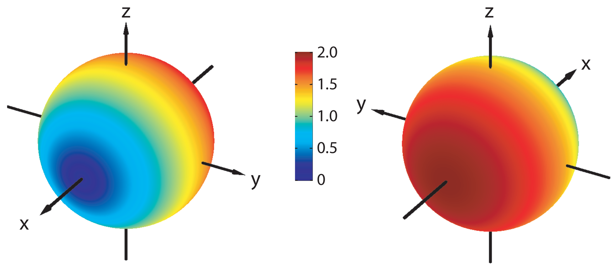
where denotes the angle between and , the angle between and , and the modulus. Both error and disturbance are thus independent of the initial system state, they are solely determined by the angle between the direction of the observable and the direction of the output operator, that is, the apparatus’ measurement axis. The error vanishes if and reaches its maximal value () if and point in opposite directions. The whole expression can be illustrated on the Bloch sphere (see Fig. 1).
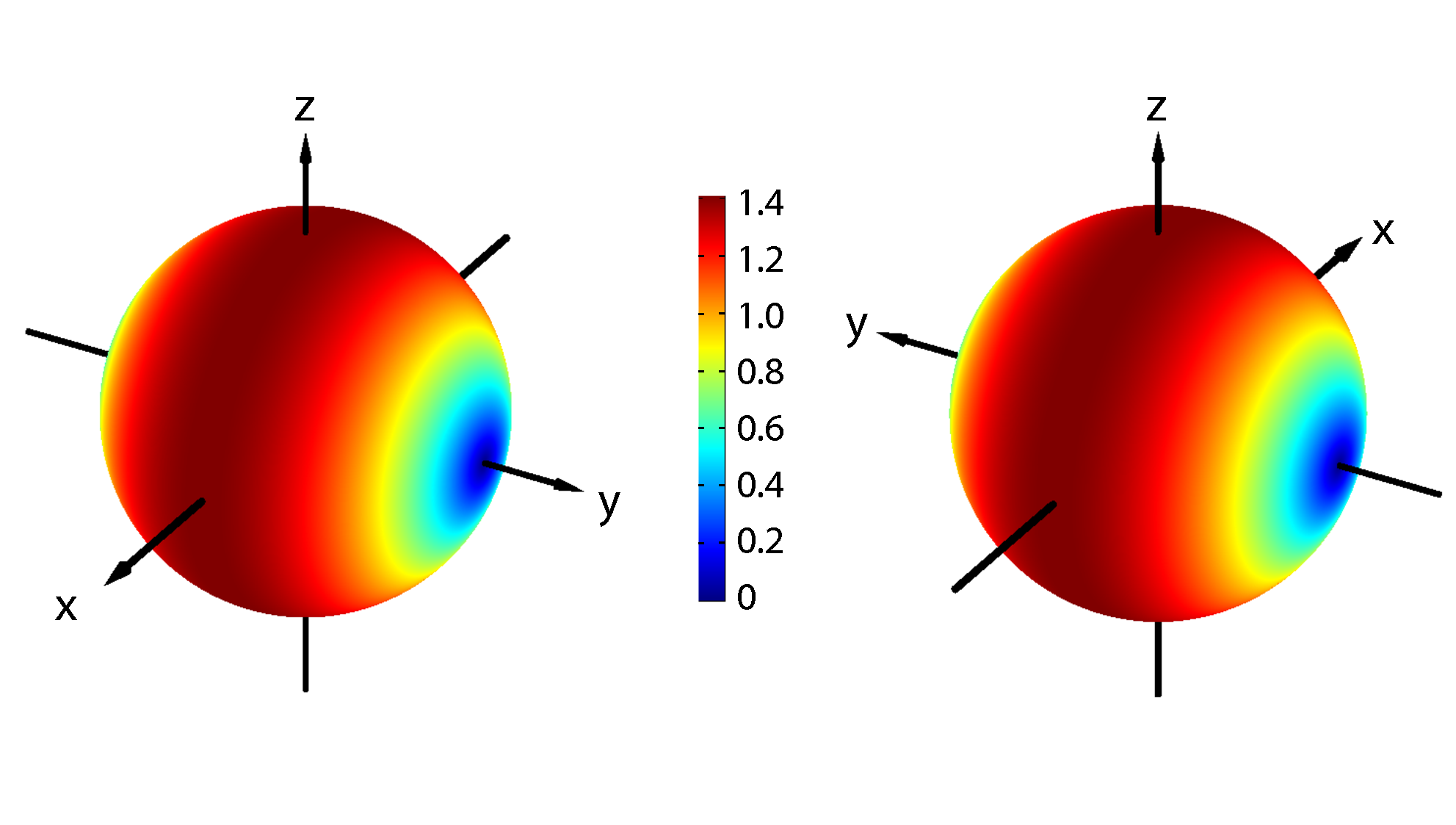
The disturbance induced on by the prior measurement of is zero if and point in the same direction, but also if points exactly in the opposite direction, that is if . In both cases and have an identical set of eigenvectors leading to a vanishing disturbance (see Eq. (22)). That’s a notable difference between the physical concepts of error and disturbance. If the two endpoints of and define the poles on the Bloch sphere, the disturbance reaches its maximal value () if lies on the corresponding equator (illustrated in Fig. 2 for ).
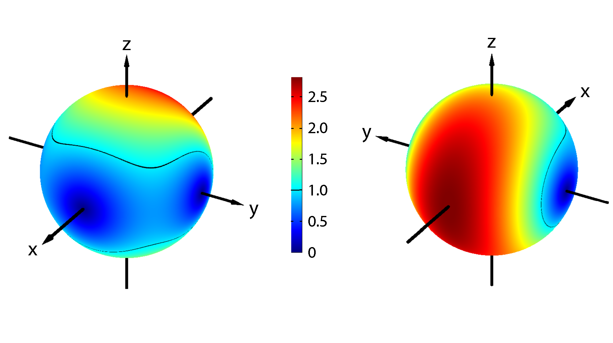
Since error and disturbance are both independent from the initial system state their product also depends only on the relative orientation of , and and can be depicted on the Bloch sphere for fixed and (see Fig. 3). In order to test if a generalized Heisenberg-like relation (Eq. (4)) is obeyed we also have to evaluate the state-dependent limit. By assigning the vector to the initial spin state using the Bloch representation of its corresponding density matrix we get
| (30) |
The limit is thus given by the volume of the parallelepiped spanned by the three vectors , , and and ranges from 0 to 1. Therefore, except for the special cases where it vanishes, we can always find regions where the product of error and disturbance is below the limit. This is an example for a general result (chap.6 in Ozawa_jso_05 ) stating that projective measurements of violate a Heisenberg-like error-disturbance uncertainty relation provided that is bounded and .
For a complete investigation of Ozawa’s error-disturbance uncertainty relation (Eq. (5)) we additionally need the standard deviations of and for an arbitrary initial state given by
| (31) |
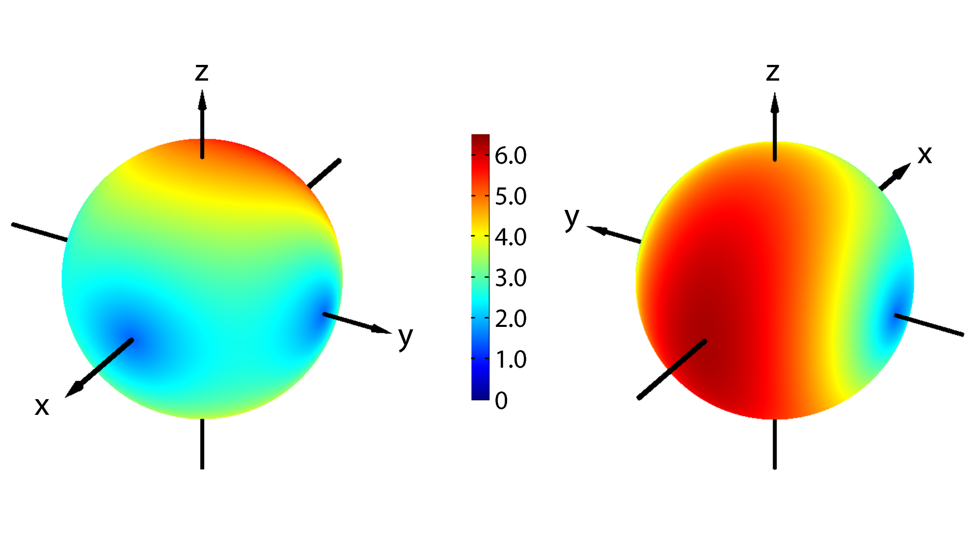
For a graphical representation of the left hand side of the Ozawa relation Eq. (5), we have to fix the observables and and the state and can then vary over the Bloch sphere and indicate the resulting values of the sum by different colors. While the Heisenberg-term is independent from the initial state, the sum in Eq. (5) changes because of the standard deviations and always lies above the lower bound given by the commutator (see Fig. 4).
IV Measurement Concept
The expressions Eqs. (21) and (22) are very convenient to calculate the explicit formulas for error and disturbance in spin measurements (Eqs. (28), (29)), but they are not suitable for designing an experiment. The output operator and the observable can not be measured simultaneously and therefore their difference is no detectable quantity. The same is true for the the change of the observable during the measurement. That’s why error and disturbance have been claimed to be experimentally inaccessible Werner2004 ; Koshino2005 . But, this obstacle can be overcome by using the expressions Eqs. (II.4) and (II.4) which read in our case of a projective spin- measurement
| (32) | |||||
and
| (33) | |||||
since . Now, error and disturbance are solely determined by expectation values of experimentally accessible operators for various input states:
The expression for the error only contains the output operator , that is the observable that’s actually measured by the apparatus. The desired observable occurs solely in two of the necessary three input states ,and . If we succeed in preparing all these known input states the error of the -measurement can be determined from the expectation values of .
For determining the disturbance we need the input states , and and the expectation values of which is just a shorthand notation for . From Eq.(18) it is given by where the are the projection operators of the output operator . Thus, if we measure immediately after the measurement of we actually perform the measurement of .
After all, our experiment needs three connected components, a preparation stage for generating the input states , , , , and , a measurement apparatus carrying out the measurement and a second apparatus performing the measurement (see Fig. 5).
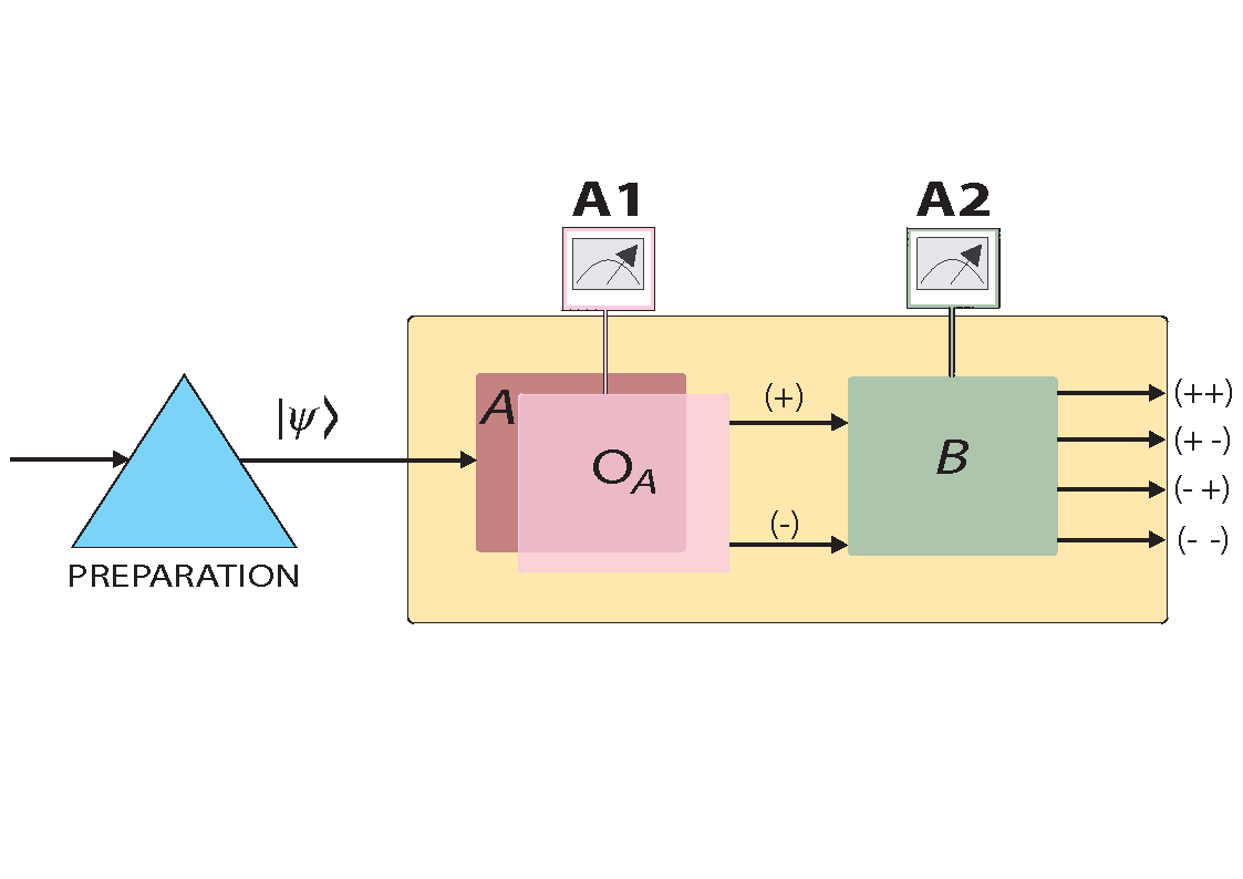
As indicated in the measurement scheme (Fig. 5) the two projective measurement of and result in four possible outcomes since every spin operator can be decomposed into two projectors belonging to the eigenvalues . Explicitly, these projectors are given by for and by for . Equivalently, we can write the projector as ket-bra of the eigenvectors which we denote by and for the operator and by and for the operator respectively. We will use this kind of notation throughout the paper for all spin states. The vector inside the ket indicates the reference axis and the sign denotes the positive or negative spin component. For directions along the Cartesian axes we omit the arrow (for example stands for the negative spin component along the -axis).
From the spectral theorem, the operators and can be decomposed into their projection operators via
| (34) | |||||
| (35) |
The indices , , , and of the output ports in Fig. 5 indicate which projections have been carried out. From the intensities at the four possible output ports, denoted by , and , the expectation value of in a state is obtained from
| (36) |
As already mentioned, the prior measurement of modifies the measurement operator of from to . The expectation values of necessary for the determination of the disturbance are obtained from
| (37) |
All expectation values necessary for the determination of error and disturbance can thus be derived from the output intensities when the input states , , , , and are applied to the joint measurement apparatuses and .
Ozawa’s relation (Eq. (5)) additionally contains the standard deviations of and in the state . For our measurement observables, the standard deviations reduce to
| (38) |
and the corresponding expression for . The expectation value of can be obtained from our experimental setup by adjusting to be equal to and then use Eq. (36). For the expectation value of , we have to turn off the measurement apparatus and apply to which then projectively measures (and not ). If we then denote the intensities of ’s two output ports by and the expectation value of is according to Eq. (35) given by . Obviously, for the expectation value of we can also turn off and only use the two output ports of in the same manner. For the actual experiment we favor this method since increasing the number of involved components usually increases the experimental error.
A final remark concerns the principle aim of our experiment. We do not seek to minimize the measurement error as one may assume at first sight. By the way, measuring the spin of a spin- particle along any direction is easily achievable with a high degree of precision. We are interested in a controlled variation of and a systematic investigation of the resulting measurement error and disturbance , which are given by Eqs. (32) and (33), in order to demonstrate the behavior of Heisenberg’s relation (Eq. (4)) in comparison to Ozawa’s relation (Eq. (5)).
V Neutron spin measurement setup
In the previous section, we have outlined the idea behind the experiment. We now want to turn to the actually performed measurements on neutron spins. The experiment was carried out at the tangential beam port of the research reactor facility TRIGA Mark II of the Vienna University of Technology. The whole setup is depicted in Fig. 6.
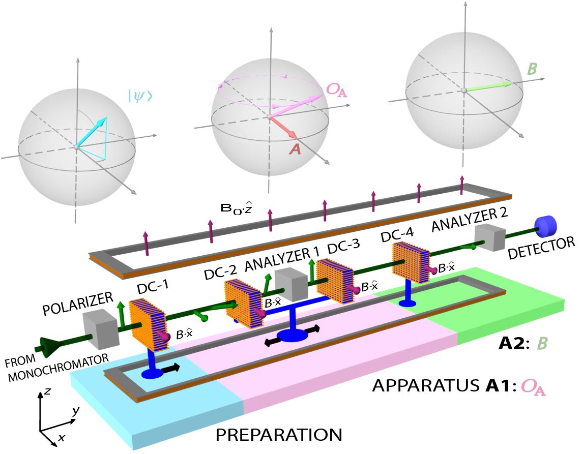
A monochromatic, thermal neutron beam with a mean wavelength of 1,96 and a cross section of about 10 (vertical) 5 (horizontal) mm2 propagates in the -direction. In the so-called preparation stage, it first crosses a bent Co-Ti supermirror resulting in an approximately 99 polarization in -direction. For the further manipulation of the spin state we use magnetic fields which interact with the neutron via the Zeeman Hamitonian . For thermal neutrons the effect of the magnetic fields on the spatial part of the wave function can be neglected Klepp08 and the action of a static magnetic field pointing in direction on the spin state is described by a unitary transformation
| (39) |
where denotes the magnetic moment of the neutron, the modulus of the magnetic field strength, and the time-of-flight through the field region. The magnetic field thus induces a rotation of the neutron polarization around the axis with an angle , commonly referred to as Larmor precession. In order to obtain any arbitrary spin state we combine the action of a 10 Gauss guide field pointing in -direction and so-called spin-flippers. The spin flipper produces a field in negative -direction which compensates the guide field and a second field that points in -direction. When the -polarized neutrons propagate through the spin flipper their polarization obtains a polar angle depending on the strength of . In the guide field, Larmor precession around the -axis is induced. Since the strength of the guide field is fixed, the azimuthal angle of the polarization is varied by changing the time-of-flight through the guide field. Thus, in order to get a certain azimuthal angle at the end of the preparation stage, we have to position the first spin flipper DC-1 properly between the polarizer and the end point of the preparation stage.
Carrying out the projective measurement of consists of two steps. At first, we have to project the initially prepared state onto the eigenstates of . To complete the measurement we then have to prepare the neutron spin in the eigenstates of . For the projection, spin-flipper DC-2 has to be positioned in the guide field such that the spin-component along the axis to be measured is rotated into the -direction. For the eigenstate belonging to eigenvalue , we need the component along , for the eigenstate belonging to , we rotate the component in -direction. The supermirror (analyzer) then selects only the -part of the wave function. The projective measurement is completed by the preparation of the measured spin-component with spin-flipper DC-3. In analogous manner to the preparation of the initial state, this is accomplished by properly positioning spin flipper DC-3 in the guide field, so that the desired state is generated at the exit of apparatus .
Note that the magnetic guide field strength and the dimensions of our experiment are chosen such that any desired direction for the output operator and any initial state can be realized.
On the state after the measurement, the -measurement is performed using the last spin-flipper (DC-4) and the analyzer. A subsequent preparation of the eigenstates of is not necessary since the counting detector is insensitive to the spin state.
In contrast to an ideal measurement, in our setup the four possible outcomes of the two projective spin measurements along and are not measured at the same time, but one after the other. At first, we adjust apparatus to measure the projection onto the positive eigenstates and of and . The resulting intensity derived from the counts/600 sec is consequently denoted by . Afterwards, we change apparatus to constitute the projection operator yielding . Then we change apparatus to measure and repeat the procedure for both eigenstates of to get and . From the four output intensities, we obtain the expectation values of and as given by Eqs. (36) and (37). The measured expectation values are normalized taking the limiting efficiency of the entire apparatus () into account, so that expectation values are bounded between . In order to get results for error and disturbance the expectation values have to be recorded for the different states , , , , and . In Fig.7, we show an explicit example of related intensity sets.
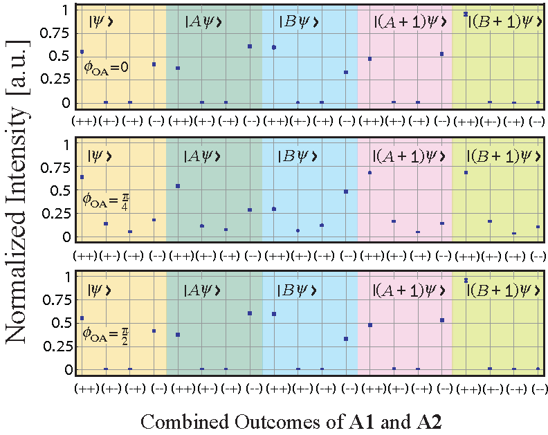
For special configurations of , , and some of these necessary states are equivalent since overall phase factors are irrelevant. For example if , and we have and .
For the measurement of the standard deviation , we chose to be and then project the initial state onto the eigenstates of . A subsequent preparation of the eigenstates and the -measurement are not necessary, that means the spin flippers DC-3 and DC-4 can be turned off. For the standard deviation , we virtually remove apparatus by turning off the spin flipper coils DC-1 and DC-2 and then use DC-3 (in combination with the guide field) to prepare the state that is then applied to apparatus that projectively measures the expectation value of .
VI Experimental Results
VI.1 Standard configuration
In the first experiment, we investigate the uncertainty relations in the so-called standard configuration where the Bloch vectors of the observables and the initial state (, , and ) are orthogonal to each other
| (40) |
Note that since all results only depend on the relative orientation of the involved quantities we can always fix one direction. Therefore, we will chose to be in all experiments. For the standard configuration, the standard deviations and the expectation value of commutator between and become maximal (see Eqs. (31) and (30))
| (41) |
In sec.III (”Theory for spin measurements”), we have depicted (Fig. 1), (Fig. 2), their product (Fig. 3), and the sum (Fig. 4) for and for all possible directions of on the Bloch sphere. In our first experimental run, we vary along the equator. is thus parameterized by its azimuthal angle yielding the direction . The theory curves for and are then given by
| (42) |
In the standard configuration, we have to prepare , , , and as input states in order to obtain the necessary expectation values that determine error, disturbance and standard deviations. The errors of the measured values for and are calculated using error propagation from the standard deviation of the count rates and considering inaccuracies of the Larmor precession angles (). The latter result mainly from inhomogeneity of the guide field along the beam.
In Fig. 8, we show the experimental outcomes for the three terms occurring in Ozawa’s relation plotted against the azimuthal angle of which we call detuning angle since it also indicates the amount of deviation between and .
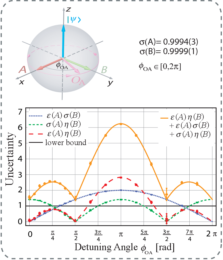
The standard deviations are independent of and their measured values are practically equal to , that’s why we can also investigate the behaviour of from the -curve and likewise the behaviour of from the -curve.
Initially, for , that is , the measurement error vanishes. When we move along the equator it increases and reaches its maximal value for ( ). Then, approaches again and decreases.
The disturbance is maximal for and vanishes when (). It has a second maximum for because a -measurement disturbs as much as an -measurement. and have the same set of eigenstates and therefore the same set of projectors which leads already for the general formula Eq. (22) to an equal expression for the disturbance. We can also verify that the disturbance vanishes again for () which follows from similar arguments for and .
The famous trade-off relation stating that when one observable is measured more precisely, the other is more disturbed has to be treated with care. This reciprocity between error and disturbance only holds for . When we move away from where to increasing we again disturb the -measurement, but at the same time the error of the -measurement increases as well since we tend towards . Then, for both decrease.
The product of error and disturbance lies below the limit given by the commutator for the majority of -values revealing the violation of the generalized Heisenberg relation (Eq. (4)). Strongest violation occurs around the regions of error-free () or disturbance-free () measurements.
Contrary to that, the sum is always above the expectation value of the commutator showing the validity of the Ozawa’s relation (Eq. (5)).
VI.2 Arbitrary direction of
Though moving along the equator of the Bloch sphere already reveals a lot of remarkable features about error, disturbance and the related inequalities a systematic investigation requires arbitrary variations of . The direction of is in general given by an azimuthal angle and a polar angle , so that which yields for error and disturbance if still and
| (43) | |||||
| (44) |
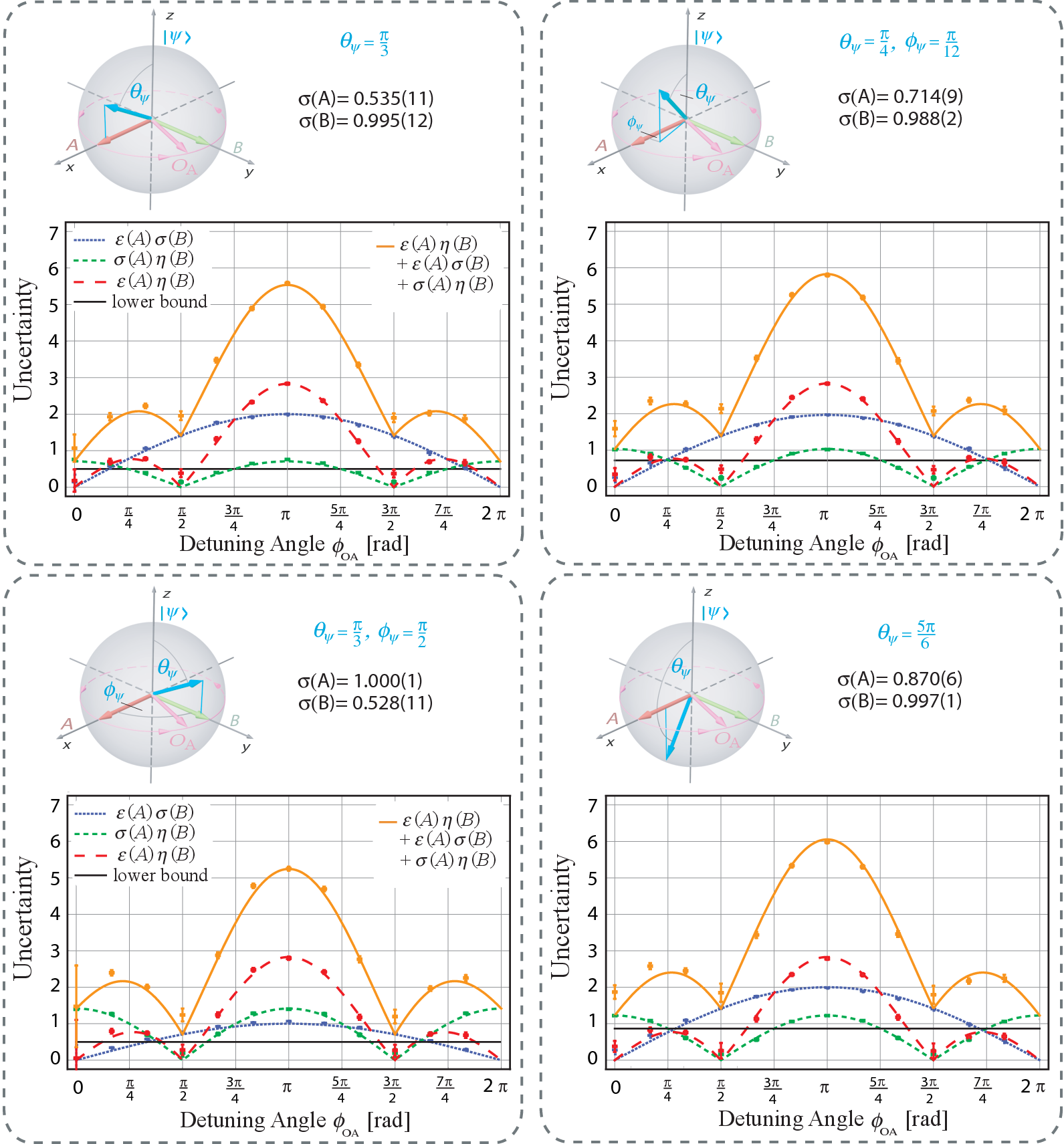
For the following experiments, we will fix the polar angle and then vary the azimuthal angle thereby realizing an evolution of along circles of latitude on the Bloch sphere (see Fig. 9).
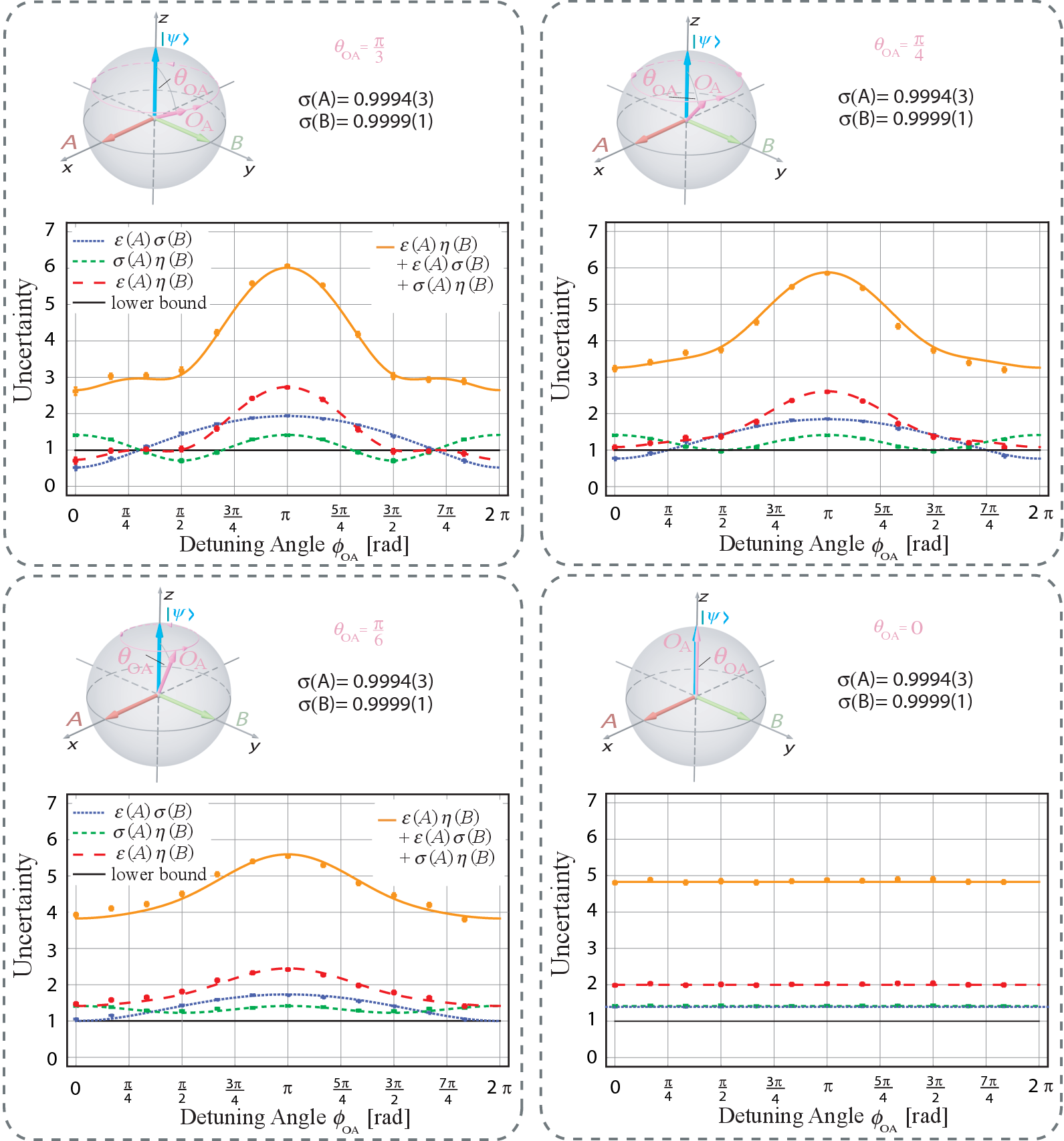
Neither error nor disturbance can then vanish completely since never coincides with , or along these paths. The - and -curves are as a whole shrunken from below. Note that we can deduce the behaviour of and from Fig. 9 since and are still 1. The shrinking effect increases the more differs from ending up in straight lines for the degenerate case .
The trade-off effect between error and disturbance is weakened, but still valid for if we move along the circles of latitude. If we move along meridians no trade-off exists at all since error and disturbance both increase. Thus, at least for spin measurements, the trade-off is not only restricted to certain regions but also to certain directions in the parameter space.
Since both error and disturbance increase their product increases as well and lies above the limit in larger and larger intervals. For the Heisenberg relation is always fulfilled (see for example top right panel of Fig.9).
Ozawa’s inequality is again always fulfilled, the sum gets shifted far above the limit when approaches the poles.
VI.3 Varying the azimuthal angle of
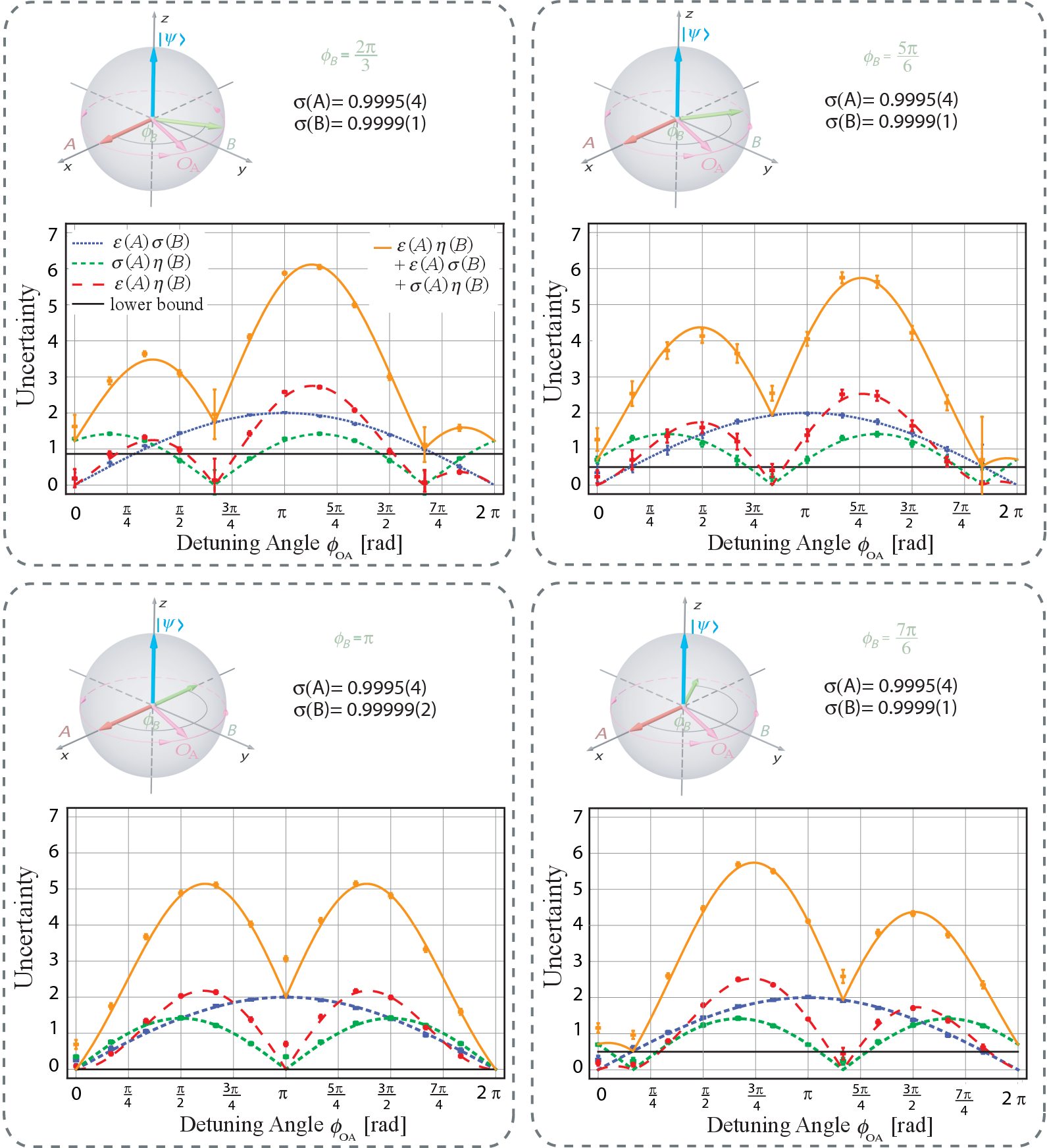
In the next step we quit the standard configuration and change the relative orientation of and by moving along the equator (see Fig. 10).
| (45) |
which leads to
| (46) |
If we also vary along the equator the error remains unaltered compared to the standard configuration but we expect the disturbance curve to be shifted an amount
| (47) |
Note that in the standard configuration which turns the sine dependence into a cosine.
The error still vanishes for and has its maximum at , the disturbance vanishes for and and has maxima in the middle between the two minima which do not correspond to the direction of or now.
Due to the loss of symmetry, the product changes considerably. Since the commutator between and additionally decreases, compared to the standard configuration, the regions where the Heisenberg error-disturbance relation is violated become smaller.
The expression is always above the limit again demonstrating the validity of Ozawa’s relation. However, in the standard configuration the sum never touched the limit whereas for shifted it approaches the lower bound. Points associated with disturbance-free measurement come closest to the limit and finally touch it for the degenerate cases and .
In this context we want to mention an interesting aspect concerning the lower bound. For the pre-measurement standard deviations in the state , the lower bound derived by Robertson Robertson29 and given by Eq. (3) was soon refined by Schrödinger Robertson_Schroedinger to be
| (48) |
where abbreviates and stands for the anti-commutator. For our observables , and the initial state the additional term explicitly reads
| (49) |
It vanishes for the standard configuration, but for non-orthogonal and it contributes. The measured standard deviations in Fig. 10 of course obey the improved relation Eq. (48). But for the error-disturbance relations, the anti-commutator term can not be added to the lower bound. This shows explicitly that the three terms of Ozawa’s relation are not bounded from below by the product of the pre-measurement standard deviations as one could naively conclude from the results of the standard configuration.
When moving along the equator we find out that the trade-off relation between error and disturbance is valid in unconnected intervals for whose positions depend on the orientation of .
VI.4 Varying the polar angle of
Now, we also introduce a polar angle for while leaving its azimuthal angle to be . The observable and the initial state are then given by
| (50) |
which leads to
| (51) |
We vary along the equator and along a circle of latitude determined by . The error remains the same as in Eq. (43) whereas the expression for the disturbance written in spherical coordinates becomes rather lengthly and we refer to the general expression Eq. (29).
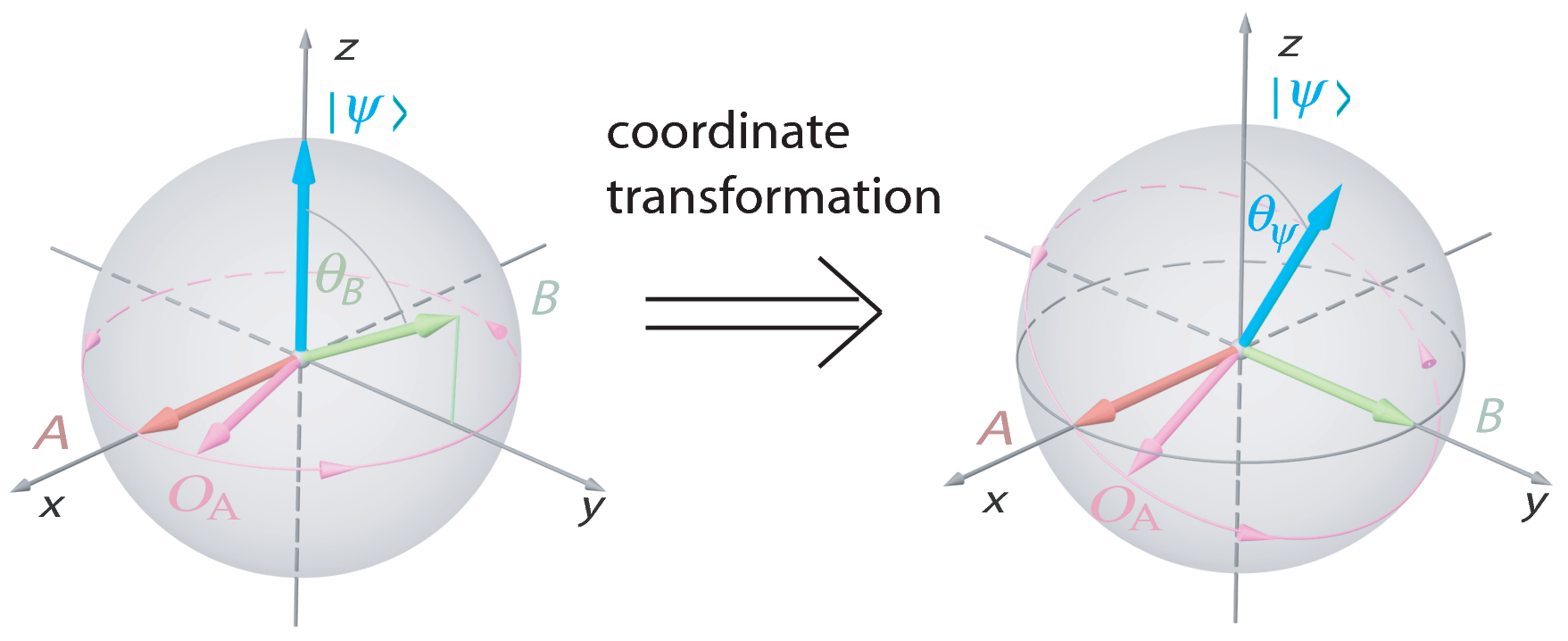
Note that we can obviously perform a coordinate transformation so that and lie in the -plane again (see Fig. 11). Then, the state gets a polar angle and the path of inclines likewise and consequently its parametrization becomes more elaborate. Nevertheless, one can also see the above experiments as a realization of this particular evolution of for , and a declined initial state.
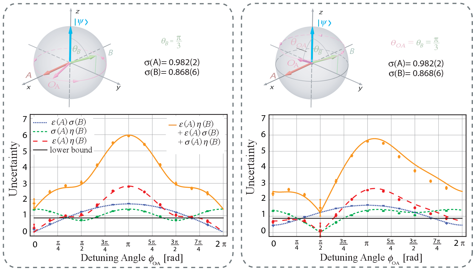
For the -variation along the equator, the error curve does not change compared to the standard configuration, the term in Fig. 12 becomes smaller due to smaller . The disturbance never vanishes totally since never coincides with or . The curve is still symmetric because the enclosed angles between and for are the same as the angles between and for .
When varies along the circle of latitude given by the situation changes. The error can not become zero since holds everywhere. The disturbance vanishes for where but the symmetry is lost. does not approach in the same manner as and so the disturbance is hardly reduced for .
VI.5 Varying the initial state
Until now, we have varied along different paths and changed the direction of . The next thing to investigate are alterations of the initial state for an already examined choice of and which should, according to the theoretical predictions, not affect error and disturbance. The parameters are given by
| (52) |
leading to
| (53) | |||||
| (54) | |||||
| (55) |
Since is varied along the equator no change for error and disturbance in comparison to the standard configuration is expected and their theory curves are thus given by Eq. (42). After dividing with the corresponding standard deviations this can be verified from the - and -curve in Fig. 13.
The plots show that the product of error and disturbance is indeed independent from the initial state. However, the lower limit changes and the regions where Heisenberg’s error-disturbance relation is fulfilled become larger when approaches the -plane.
The left-hand-side of Ozawa’s relation also contains the standard deviations and therefore changes with the initial state and still lies above the limit.
VII Discussion
In our previous letter Erhart12 , we reported an experiment for the particular case where error and disturbance of a neutron’s spin-component measurements obey Ozawa’s new relation Eq. (5) but violate the old one Eq. (4) in the whole range of the experimental parameter. The old relation is extended from Heisenberg’s original relation Eq. (1) between the error of a position measurement and the induced disturbance on the momentum. Although mainly motivated by thought experiments and in its mathematical derivation based on unjustified assumptions, Heisenberg’s old relation for measurement error and disturbance prevailed and was regarded as a peculiarity of quantum mechanics for a long time. The important step for the test of error-disturbance uncertainty relations is to give clear and consistent definitions of error and disturbance for quantum measurements. This is done by Eqs.(12) and (13). Here, we again investigate these relations in the -spin system, but enlarge our parameter range in comparison to Erhart12 . For projective spin- measurements, error and disturbance are determined by three (Bloch) vectors , and , characterizing the spin observables and and the actual measurement operator . In particular, the error (disturbance) only depends on the deviation angle between () and , which is described in Eq. (28) (Eq. (29)) and depicted in Fig. 1 (Fig. 2). It is worth noting here that error and disturbance are independent from the initial quantum state which follows straight-forward from the properties of the Pauli-matrices.
Our measurement strategy is based on the expansion of error and disturbance in terms of expectation values of outcomes in three different input states given by Eqs. (II.4) and (II.4) reminding of a quantum process tomography NielsenChuang_JModOpt_1997 ; Poyatos . There is another experimental strategy based on weak values lund_wiseman_njop2010 ; Steinberg_PRL_2012 ; Hofmann_arxiv_2012 . They insist that “if the system is weakly measured before the measurement apparatus the precision (error) and disturbance can be directly observed in the resulting weak values” Steinberg_PRL_2012 and claim our method to be indirect. Although it is not clear in what sense the measurements are direct and indirect, we consider here possible arguments: The determination of error and disturbance is done (i) whether by using a single incident state or a combination of some states and/or (ii) whether for single events or for an ensemble. For the point (i), we point out the fact that the incident state is affected by some operation before the measurements A and B in both cases. In the weak-value strategy, weak measurements actually demands interaction with the system, which inevitably makes backreaction on the system (however weak they may be), otherwise no information of the system will be derived: after interactions through needed weak-value measurements, the incident state is no more the same as it was. In contrast, the measurements of A and B are done just after the incident state goes through the operation of , A, B, A+, or B+ in the tomographic strategy. Only the difference between them is that the operation is weak or strong. For the point (ii), as is stated in one of the above papers, “Experimentally, the problem with weak values is that they cannot be confirmed by precise measurements on individual systems” Hofmann_arxiv_2012 : experimental determination of the error and disturbance requires measurements on a set of an ensemble, which is a common feature of both approaches. This is a clear statement of abandonment of determining the error and disturbance for single events by using neither strategies. Another point is to be mentioned: in comparison of the two graphs in Fig. 5 of Erhart12 (respectively, the corresponding part of Fig. 8 in this work) and Fig. 4 Steinberg_PRL_2012 , the accuracy of the former is clearly much higher than the latter.
Conscientious readers may presume without difficulty that the new uncertainty relation could be reformulated as
| (56) |
by just adding Robertson’s and Ozawa’s inequality (Eqs. (3) and (5)). Although it seems appealing to consider the left hand side as the product of a newly defined “overall” error and “overall” disturbance, given by the sum of measurement-induced error for [disturbance on ] and measurement-independent intrinsic fluctuation (standard deviation) of [], the “overall” lower bound is less tight than Eqs. (3) and (5) considered separately.
Finally, we are aware that a completely different quantification of uncertainty relations, viz, in terms of entropy, has been developed. For instance, a relation for position and momentum was derived first Mycielski1975 , followed by a generalization for arbitrary pairs of observables Deutsch1983 . An improved version suggested in Kraus_PhysRevD_1987 and proven in Maassen1988 has the form
| (57) |
where [] denotes the Shannon entropy of the probability distribution of the outcome and [] represent non-degenerating eigenstates of A [B]. Recently, a stronger entropic uncertainty relation for an entangled system was presented Berta2010 and studied in an optical setup Li2011 . The entropic uncertainty relations describe informational contents and do not refer to the interaction of quantum measurements. They rather represent a generalization of Robertson’s relation (Eq. (3)) for probability distributions for which the standard deviation has little physical meaning. Though, it would be interesting if the universally valid uncertainty relation of Ozawa (Eq. (5)) also has an entropic counterpart.
VIII Conclusion
In Heisenberg’s original formulation, the uncertainty principle refers to a relation for the error in the measurement of a certain observable and the thereby induced disturbance on another observable. However, his famous relation has been based on thought experiments or a rather heuristic argument with unsupported assumptions. A recent development of rigorous treatments of quantum measurement has enabled us to reformulate the error-disturbance relation and lead to a universally valid relation.
In the experiment presented here, we have investigated this relation for projective neutron spin measurements. The two non-commuting observables under consideration are spins along different directions which are measured successively. By using a tomographic procedure, based on applying three different states generated from the initial system state on the joint measurement apparatuses, the error of the first measurement and the disturbance induced on the second observable can be determined from the output intensities. By detuning the measurement axis of the first apparatus we can study the variation of error and disturbance. Together with the Bloch vector of the initial system state, the directions of the two spin observables and of the measurement axis constitute the relevant parameters determining all quantities occurring in the uncertainty relations.
In our neutron-optical experimental runs, we have at first fixed the observables and the initial state, and then varied the detuned measurement axis along equilatitude circles on the Bloch sphere. For various representative configurations, the measured values for error and disturbance are in excellent agreement with the theory curves. They are independent of the initial state and are solely determined by the enclosed angle between the measurement axis and the first or second spin axis, respectively. The results demonstrate that Heisenberg’s error-disturbance relation can always be violated for a non-vanishing lower limit. In contrast, Ozawa’s new inequality always holds. Furthermore, we conclude that increasing error does not always lead to decreasing disturbance and vice versa in spin measurements. Such a reciprocal behavior occurs only in certain areas and along certain directions. Thus, our results give an experimental demonstration that the generalized form of Heisenberg’s error-disturbance relation has to be abandoned.
References
- (1) W. Heisenberg, Z. Phys. 43 (1927).
- (2) E. Arthurs and J. L. Kelly, Bell System Technical Journal 44, 725 (1965).
- (3) L. E. Ballentine, Rev. Mod. Phys. 42, 358 (1970).
- (4) P. Busch, International Journal of Theoretical Physics 24, 63 (1985).
- (5) K. Kraus, Phys. Rev. D 35, 3070 (1987).
- (6) J. Hilgevoord and J. Uffink, A new view on the uncertainty principle, in Sixty-Two years of Uncertainty, Historical and Physical Inquiries into the Foundations of Quantum Mechanics, edited by A. Miller, pp. 121–139, New York, 1990, Plenum.
- (7) H. Martens and W. Muynck, Foundations of Physics 20, 357 (1990).
- (8) H. Martens and W. M. de Muynck, Journal of Physics A: Mathematical and General 25, 4887 (1992).
- (9) D. Appleby, International Journal of Theoretical Physics 37, 1491 (1998).
- (10) M. Ozawa, Physics Letters A 299, 1 (2002).
- (11) W. Heisenberg, The Physical Principles of Quantum Mechanics (University of Chicago Press, Chicago, IL, 1930).
- (12) E. H. Kennard, Zeitschrift für Physik A Hadrons and Nuclei 44, 326 (1927).
- (13) C. G. Shull, Phys. Rev. 179, 752 (1969).
- (14) H. Kaiser, S. A. Werner, and E. A. George, Phys. Rev. Lett. 50, 560 (1983).
- (15) A. G. Klein, G. I. Opat, and W. A. Hamilton, Phys. Rev. Lett. 50, 563 (1983).
- (16) O. Nairz, M. Arndt, and A. Zeilinger, Phys. Rev. A 65, 032109 (2002).
- (17) M. Ozawa, Phys. Lett. A 318, 21 (2003).
- (18) H. Wiseman, Foundations of Physics 28, 1619 (1998).
- (19) H. P. Robertson, Phys. Rev. 34, 163 (1929).
- (20) E. Arthurs and M. S. Goodman, Phys. Rev. Lett. 60, 2447 (1988).
- (21) S. Ishikawa, Reports on Mathematical Physics 29, 257 273 (1991).
- (22) M. Ozawa, Quantum limits of measurements and uncertainty principle, in Quantum Aspects of Optical Communications, edited by C. Bendjaballah, O. Hirota, and S. Reynaud, , Lecture Notes in Physics Vol. 378, pp. 1–17, Springer Berlin / Heidelberg, 1991.
- (23) M. Ozawa, Phys. Rev. A 67, 042105 (2003).
- (24) M. Ozawa, Annals of Physics 311, 350 (2004).
- (25) M. Ozawa, Journal of Optics B: Quantum and Semiclassical Optics 7, S672 (2005).
- (26) R. F. Werner, Quant. Inf. Comput. 4, 546 562 (2004).
- (27) K. Koshino and A. Shimizu, Physics Reports 412, 191 (2005).
- (28) J. Erhart et al., Nature Physics 8, 185 (2012).
- (29) A. P. Lund and H. M. Wiseman, New Journal of Physics 12, 093011 (2010).
- (30) R. Mir et al., New Journal of Physics 9, 287 (2007).
- (31) M. Ozawa, Physics Letters A 335, 11 (2005).
- (32) L. A. Rozema et al., Phys. Rev. Lett. 109, 100404 (2012).
- (33) M. Ozawa, Journal of Mathematical Physics 25, 79 (1984).
- (34) K. Kraus, A. Böhm, J. D. Dollard, and W. H. Wootters, editors, States, Effects, and Operations Fundamental Notions of Quantum Theory, , Lecture Notes in Physics, Berlin Springer Verlag Vol. 190, 1983.
- (35) J. Klepp et al., Phys. Rev. Lett. 101, 150404 (2008).
- (36) E. Schrödinger, Sitzungsberichte der Preussischen Akademie der Wissenschaften, Physikalisch-mathematische Klasse 14, 296 (1930), engl. translation at http://arxiv.org/abs/quant-ph/9903100.
- (37) I. L. Chuang and M. A. Nielsen, Journal of Modern Optics 44, 2455 (1997).
- (38) J. F. Poyatos, J. I. Cirac, and P. Zoller, Phys. Rev. Lett. 78, 390 (1997).
- (39) H. F. Hofmann, ArXiv e-prints (2012), 1205.0073.
- (40) I. Bialynicki-Birula and J. Mycielski, Communications in Mathematical Physics 44, 129 (1975).
- (41) D. Deutsch, Phys. Rev. Lett. 50, 631 (1983).
- (42) H. Maassen and J. B. M. Uffink, Phys. Rev. Lett. 60, 1103 (1988).
- (43) M. Berta, M. Christandl, R. Colbeck, J. M. Renes, and R. Renner, Nature Physics 6, 659 (2010).
- (44) C. F. Li, J. S. Xu, X. Y. Xu, K. Li, and G. C. Guo, Nature Physics 7, 752 (2011).