Evaluating Laguerre-Gaussian beams with an invariant parameter
Abstract
We define a new parameter about Laguerre-Gaussian (LG) beams, named , which is only related to mode indices and . This parameter is able to both evaluate and distinguish LG beams. The values are first calculated theoretically and then measured experimentally for several different LG beams. Another mode quality parameter, value, is also measured. The comparison between and shows same trend for the quality of LG mode, while the measurement of is much easier than .
Vortex beam attracts many interests for carrying orbital angular momentum (OAM), i.e., the vortex beam with an azimuthal phase structure carries OAM of per photon Al . Light beams possessing OAM of , where can take any integer value, have a potential ability to carry a large information since the unlimited range of forms an unbounded Hilbert space GM ; GG . One typical example of vortex beams is high-order Laguerre-Gaussian (LG) mode, which is one of transverse mode solutions for laser cavities. Practical generation of LG modes is always achieved using cylindrical lens mode converter MDC , spiral phase plate PP or fork hologram fork1 ; fork2 . Many applications of beams with OAM have been already demonstrated, from optical tweezers OT to higher-dimensional quantum information encoding QIE .
To obtain accurate result of an experiment with LG modes, it would be better to evaluate LG beams first. By now, a standard parameter, parameter M2 , can make it. The value is the ratio of the beam parameter product of an actual beam to that of an ideal Gaussian beam at the same wavelength. It can be used to quantify the degree of variation how the actual beam is different from such an ideal beam. The value can also sort the OAM of LG mode according to ( and are the mode indices). However, credible measurement of the value need to record many intensity cross-sections along the propagation direction, especially around the waist and far field ISO . So, despite the measurement hardness, parameter will also be invalid to evaluate the beam’s quality or sort its OAM if only a cross-section intensity picture of an LG beam is given. Recently, a new way of making Fourier transform of the cross-section intensity picture can sort the beam’s OAM intensity . But this method is not very accurate and cannot give an evaluation of the quality of LG modes. In this letter, we define a new parameter for LG beams which can both evaluate the quality of the LG mode and sort the OAM through only one cross-section intensity picture. The parameter, called value ( and are mode indices of LG beams), is firstly proved to be independent to the size or the observation position of the LG beam and only correlated with mode indices and . Then, we carry out an experiment to demonstrate the theory. To make a comparison, the parameter is also measured.
The intensity of LG beams in the x-axis can be given by:
| (1) |
where is the electromagnetic field amplitude, is a generalised Laguerre polynomial, is the radial mode index, is the topological charge, , , , , and .
Fig.1 shows the relative cross-section intensity of a beam with and . is the first maximum value of function in the positive part of the x-axis and is equal to half of the . In Fig.1, and are the first two points on the x-axis where the intensity function reaches , and is the point of reaching .
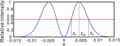
We define from the intensity function I:
| (2) |
Let equals , . So can be calculated by . Next, we need to prove that and are only associated with mode indices and .
The maximum value can be obtained from
| (3) |
And from Eq.(3), it is obvious that can be calculated from:
| (4) |
Because the function just depends on mode indices and , obtained from Eq.(4) is also only related to and .
Then, and can be calculated from the following equation:
| (5) |
Considering that and the form of the function are both just associated with mode indices and , we can conclude that and calculated from Eq.(5) is just related to and . Hence, when mode indices and of LG beams are given, the value calculated by is unique.
It is obvious that Eq.(5) has no analytical solution. However we can we can numerically solve it. Some of the values calculated numerically by computer are listed in Table I.
| 1 | 2 | 3 | 4 | |
|---|---|---|---|---|
| 0 | 0.4170 | 0.7482 | 1.0093 | 1.2316 |
| 1 | 0.4754 | 0.8877 | 1.2265 | 1.5219 |
| 2 | 0.4821 | 0.9081 | 1.2632 | 1.5757 |
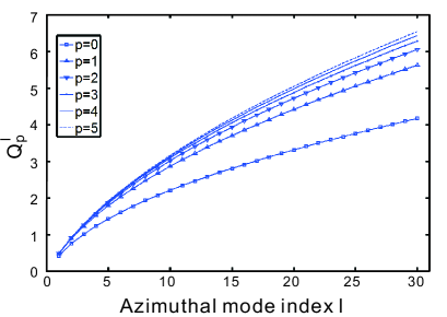
More theoretical values are presented in Fig.2, from which we can know that the value is a strictly increasing function corresponding to when is fixed. So, value of LG beam can be used to evaluate the mode quality and estimate OAM number. Experimentally, we can take just one picture at any distance because the is independent with . To measure the OAM of a high-order LG beam, the mode index of a LG beam can be firstly determined by the radial structure because the intensity cross-section consists of concentric rings. After the mode index of a LG beam is known, we can calculate of the beam and then the mode index can be estimated by the one-to-one relationship between the value and .
To demonstrate the validity of this method, we experimentally generated some high-order LG beams and measured their values. In this experiment, computer-generated holograms were used to produce high-order LG modes with ranging from 1 to 3 and (pictures are shown in the middle of Fig.4). A charge coupled device (CCD) was used to record the cross-section intensity. Particularly worth mentioning is that the CCD camera must respond linearly to the light intensity. A power meter was used to test and verify the linear response of CCD camera to the light intensity in our experiment.
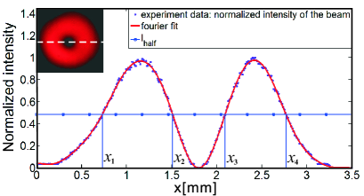
For every mode, we recorded a far-field intensity pattern every 10 away from the hologram. Then, we found out the center of each circle facula on every photo, and extracted the intensity data in direction and direction through the facula center, just as Fig. 4 showing. In addition, the values of these experimental beams were also measured. The theoretical values of LG beams scale with their mode indices and according to .
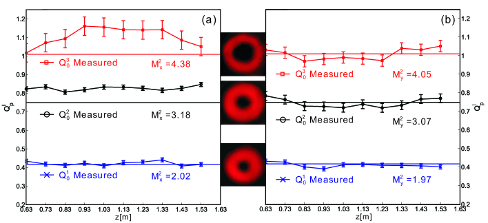
The results are shown in Fig.4 and a comparison between theoretical values and measured values (LG01, LG02 and LG03) is made. At least two features can be gotten from Fig.4. First, we can see that different LG beams possess of different values, and values are stable at different observation positions in a large range. It means that can be measured conveniently at any place. To reduce the error from measurement, it is pragmatic to make an average of values measured at different places for a beam. Second, the values have same trend with the values, i.e., when values are close to the theoretical values (e.g. in and directions, and in direction), values are also good; when values have a large deviation to the theoretical values (e.g. and in direction), values are also bad. This performance shows that can be used to evaluate the mode quality of LG beams as , while is simpler than in practical measurement.
also provides a convenient way to sort the OAM of LG beams. From Fig.2, we can conclude that the when the mode index is certain, the value of is directly determined by the value of the beam. Up to now, many approaches have been proposed to measure the OAM of light beams by interference interference1 ; interference2 , diffraction double ; MPI ; annular ; Triangular and atomic ensembles atom . And some excellent works based on cascade of Mach-Zehnder interferometers M-Z and image reformatting IT can even measuring the OAM of single photons. What all these methods have in common is that they all identify the OAM states based on phase information. In contrast to that, the method of measuring is based on intensity information and can be achieved more convenient by only a CCD camera. However, due to the intensity distribution detecting, the sign of can not be determined from the value.
In conclusion, we define a new parameter for LG model and then theoretically prove that it is a function only relating to mode indices and . And the experiment results also support the theory. Furthermore, the values of several LG beams are compared with the values in our experiment, which shows that measuring value is a simple method to evaluate the quality of LG mode. can also be used to determine the OAM number of LG beams.
This work is supported by the Fundamental Research Funds for the Central Universities, Special Prophase Project on the National Basic Research Program of China (Grant No. 2011CB311807), and the National Natural Science Foundation of China (Grant Nos. 11004158, 11074198, 11174233 and 11074199).
References
- (1) L. Allen, M. W. Beijersbergen, R. J. C. Spreeuw, and J. P. Woerdman, Phys. Rev. A 45, 8185 (1992).
- (2) G. Molina-Terriza, J. P. Torres, and L. Torner, Phys. Rev. Lett. 88, 013601 (2001).
- (3) G. Gibson, J. Courtial, M. J. Padgett, M. Vasnetsov, V. Pas’ko, S. M. Barnett, and S. Franke-Arnold, Opt. Express 12, 5448 (2004).
- (4) M. W. Beijersbergen, L. Allen, H. E. L. O. Vanderveen, and J. P. Woerdman, Opt. Commun. 96, 123 (1993).
- (5) M. W. Beijersbergen, R. P. C. Coerwinkel, M. Kristensen, and J. P. Woerdman, Opt. Commun. 112, 321 (1994).
- (6) M. S. S. I. V. Basistiy, M. S. Soskin, and M. V. Vasnetsov, Opt. Commun. 119, 604 (1995).
- (7) G. Brand, Am. J. Phys. 67, 55 (1999).
- (8) M. E. J. Friese, J. Enger, H. Rubinsztein-Dunlop, and NR. Heckenberg, Phys. Rev. A 54, 1593 (1996).
- (9) J. T. Barreiro, T. C. Wei, and P. G. Kwiat, Nature Physics 4, 282 (2008).
- (10) C. Schulze, D. Flamm, M. Duparré, and A. Forbes, Opt. Lett. 37, 4687 (2012).
- (11) Lasers and laser-related equipment - Test methods for laser beam widths, divergence angles and beam propagation ratios, BRITISH STANDARD BS EN ISO 11810-2:2007.
- (12) S. Prabhakar, A. Kumar, J. Banerji, and R. P. Singh, Opt. Lett. 36, 4398 (2011).
- (13) M. J. Padgett, J. Arlt, N. Simpson, and L. Allen, Am. J. Phys. 64, 77 (1996).
- (14) R.F. Liu, J.L. Long, F.R. Wang, Y.L. Wang, P. Zhang, H. Gao, and F.L. Li, arXiv:1305.5631.
- (15) H. I. Sztul and R. R. Alfano, Opt. Lett. 31, 999 (2006).
- (16) G. C. G. Berkhout and M. W. Beijersbergen, Phys. Rev. Lett. 101, 100801 (2008).
- (17) C. S. Guo, L. L. Lu, and H. T. Wang, Opt. Lett. 34, 3686 (2009).
- (18) J. M. Hickmann, E. J. S. Fonseca, W. C. Soares, and S. Chávez-Cerda, Phys. Rev. Lett. 105, 053904 (2010).
- (19) L. Han, M. Cao, R. Liu, H. Liu, W. Guo, D. Wei, S. Gao, P. Zhang, H. Gao, and F. Li, Europhy. Lett. 99, 34003 (2012).
- (20) J. Leach, M. J. Padgett, S. M. Barnett, S. Franke-Arnold, and J. Courtial, Phys. Rev. Lett. 88, 257901 (2002).
- (21) G. C. Berkhout, M. P. Lavery, J. Courtial, M. W. Beijersbergen, and M. J. Padgett, Phys. Rev. Lett. 105, 153601 (2010).